
Even in the modern world, power outages are not uncommon. At the same time, devices through which a person interacts with the Internet are becoming more portable, laptops, phones, tablets. However, when the power is cut off, the Internet connection also breaks, since the universally used Wi-Fi routers are powered by an electric network. This article discusses how to solve this problem.
This device is able to power a standard wireless router, charge a smartphone or any device with a power supply of 5 V and a current of up to 1 A.
Step 1: Prerequisites and Tools
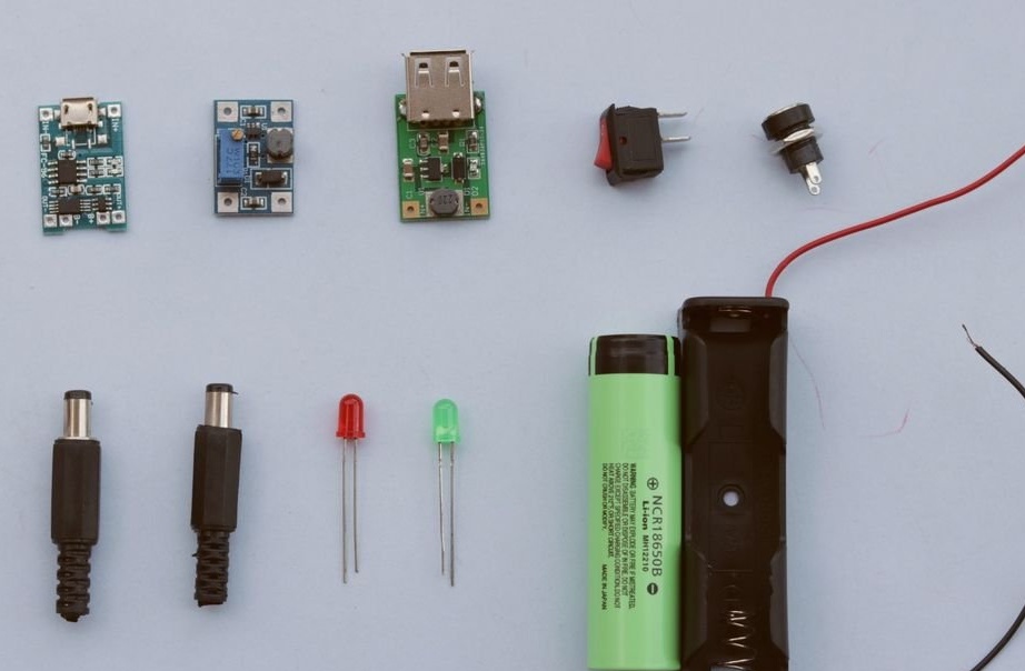
Necessary components:
1. TP4056 charging module
2. Step-up DC / DC converter
3. 5V boost converter
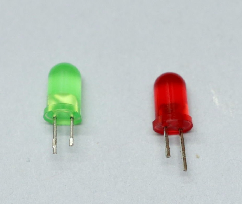
4. LEDs
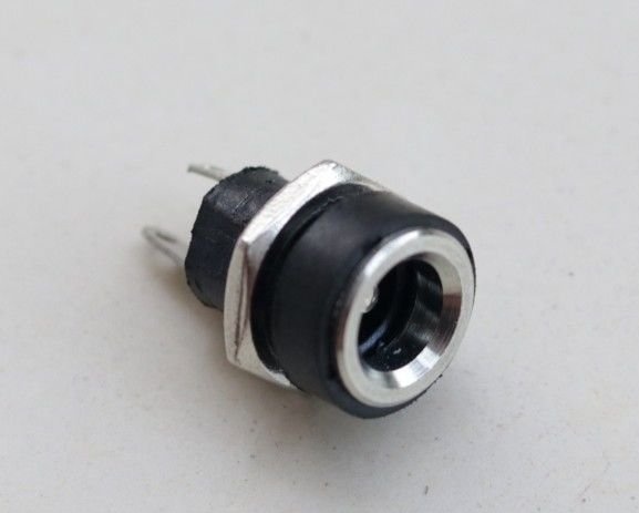
5. Connector 2.1 x 5.5 mm female
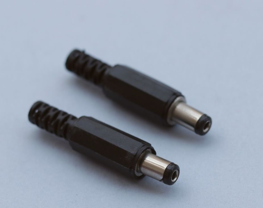
6. Connector 2.1 x 5.5 mm male (2 pcs.)
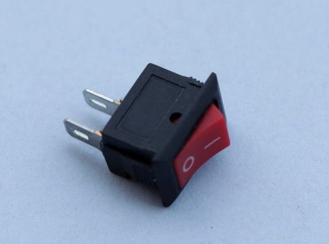
7. Power switch
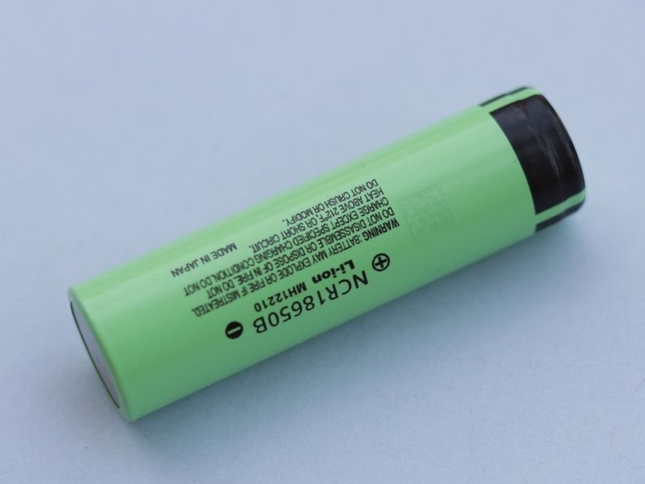
8. 18650 battery
9. Holder 18650
10. Wires
11. Heat Shrink Tubing
12. PLA Filament
Tools used:
1. Soldering iron
2. Hot glue gun
3. Nippers
4. Wire stripper
5. 3D printer
Step 2: How does the circuit work?
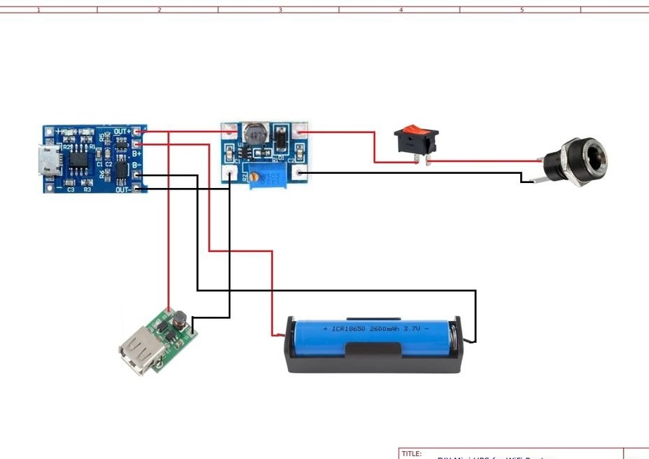
The operation of the circuit is very simple, under normal conditions, the mains power is consumed by the charger to charge the 18650 battery and to supply power to the router. During a power outage, the battery accumulated charge is used to power the router.
In a schematic diagram, the 18650 battery is connected to the TP4056 charging module. The output of the TP4056 module is connected to two boost converters: one to power the router (12 V), and the other to the USB connector (5 V) for charging the smartphone. The output voltage of the boost converter (SX1308 module) is set by a multi-turn trimmer mounted on the board. The voltage must be set in accordance with your modem, in most cases it is 12 V, but it can also be found at 9 V. You can find out either on the power supply or on the device itself. The output of the boost converter (SX1308) is connected to an external 5.5 mm jack via a switch.
Step 3: Battery Selection
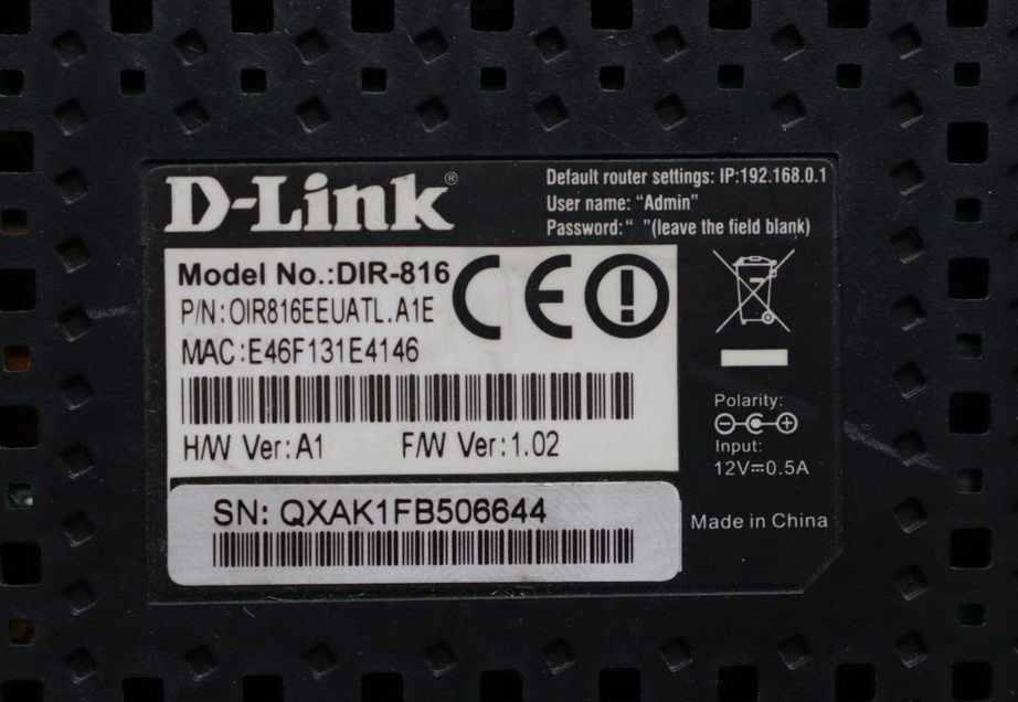
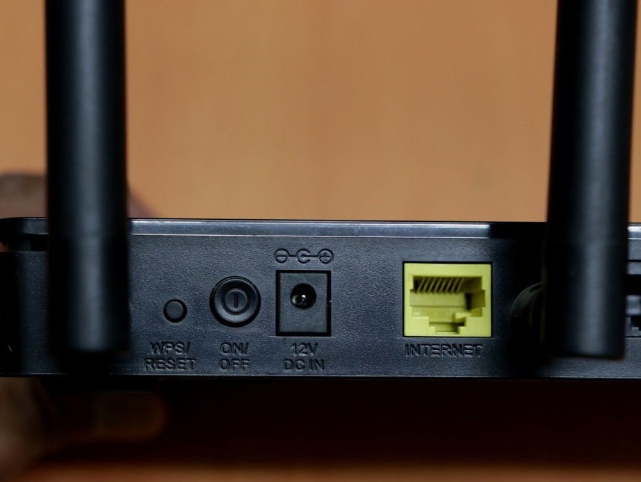
First, check the characteristics of your router / modem. In this case, the power consumption of the router is 12 V and 0.5 A. Thus, the power requirements for the router are 12 x 0.5 = 6 watts.
The author considered a standby time of 30 minutes. Thus, 6 x 0.5 = 3 W / h is required.
The rated voltage of the 18650 battery is 3.7 V.
Required capacity = 3 W / h / 3.7 V = 0.810 Ah; = 810 mAh
The same battery is also used to charge the smartphone. Suppose you need to charge the phone to 35-40% only for emergency use. The battery of the author’s smartphone (One Plus 6) is designed for 3300 mAh.
The final required capacity is = 810 + 3300 x 0.4 = 2130 mAh
Taking into account the losses in the converter, a Panasonic 3400 mAh battery was selected for this mini-UPS.
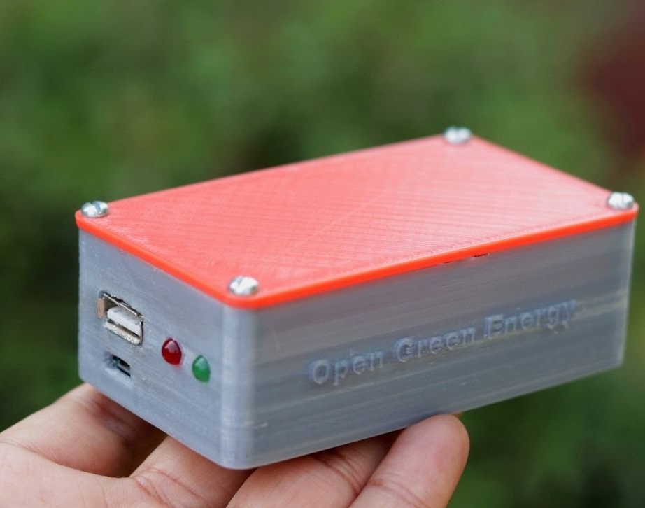
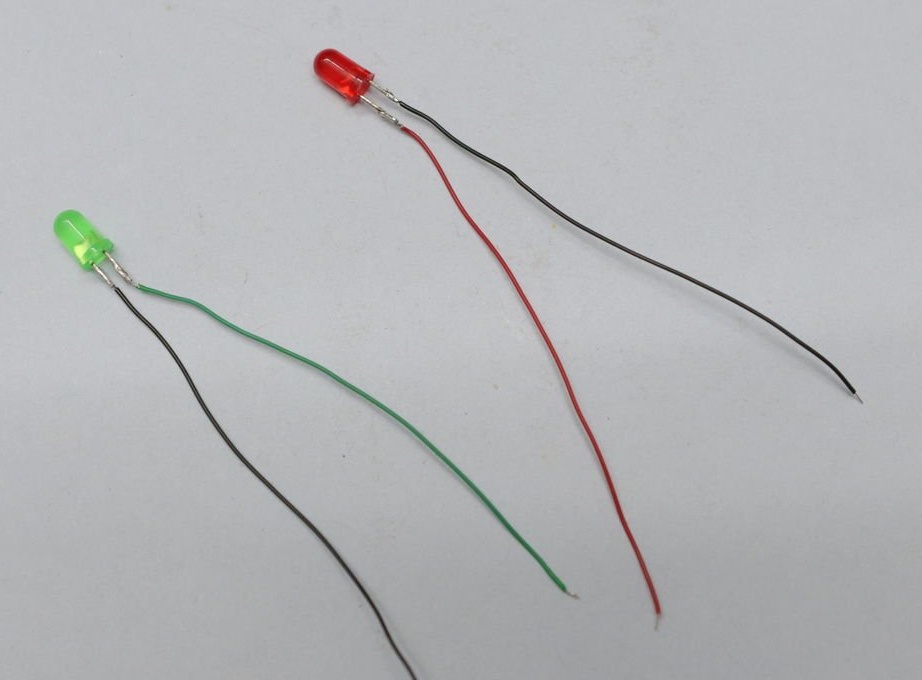
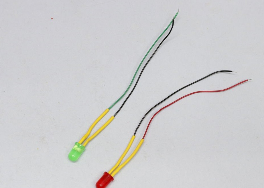
Step 4. Conclusion of LEDs on the front panel
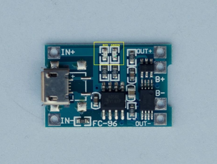
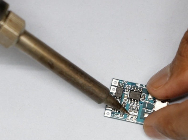
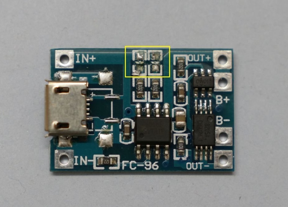
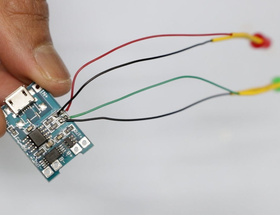
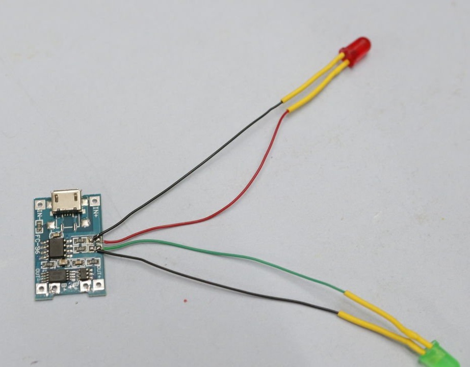
The charging status of the 18650 battery is displayed by two LEDs on the TP4056 module. To monitor the charge, the LEDs were placed on the front panel of the device.
Step 5: Connecting the Holder
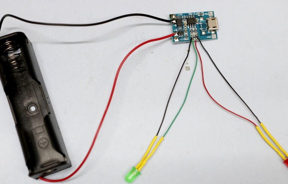
First apply a small amount of solder to the B + and B- pads on the TP4056 module.
Then solder the red wire of the battery holder to terminal B +, and the black wire to terminal B- of the TP4056 module.
Step 6: Connect Boost Converters
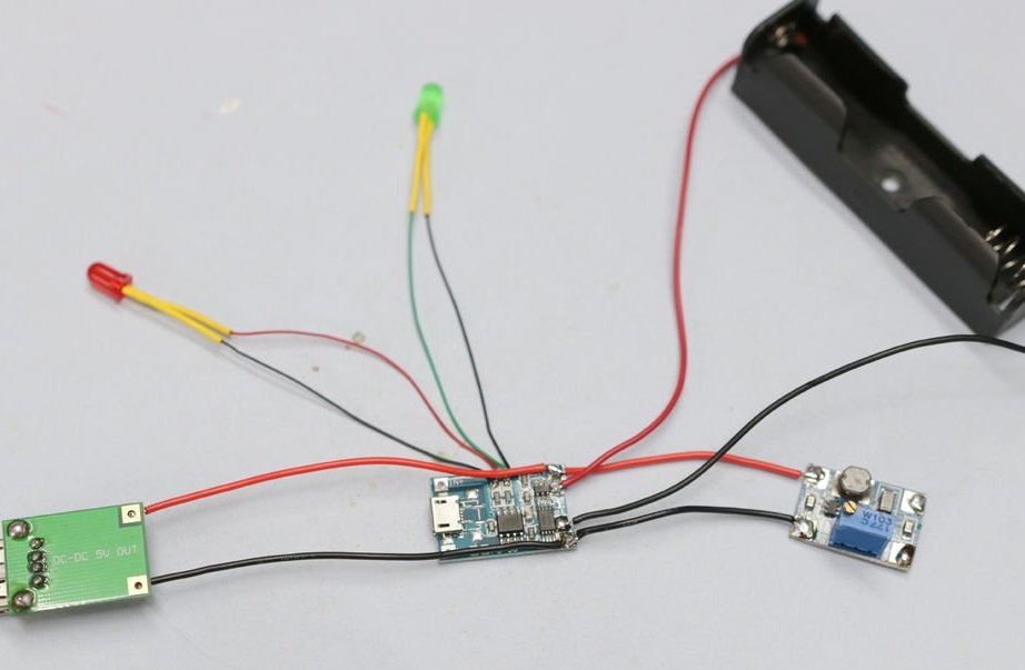
As in the previous step, apply a small amount of solder to the Out + and Out terminals of the TP4056 module.
Then solder the wire from the boost converters to the TP4056 module, as shown in the diagram.
SX1308 Module:
VIN + connects to Out +
GND connects to Out-
USB Boost Converter:
VIN + connects to Out +
VIN- connects to Out-
Step 7: Prepare the Connector and Switch
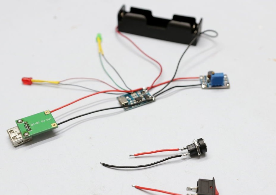
Solder the wires to the power button and connector. Do not solder the wires to the modules until this is done after installation in the housing.
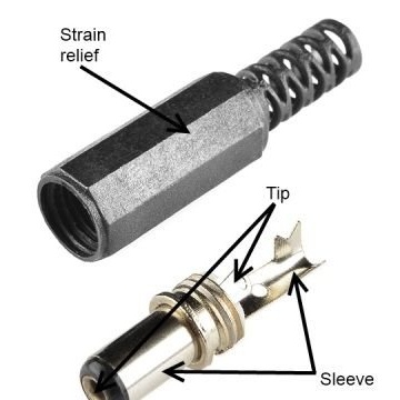
Step 8: Prepare the Adapter
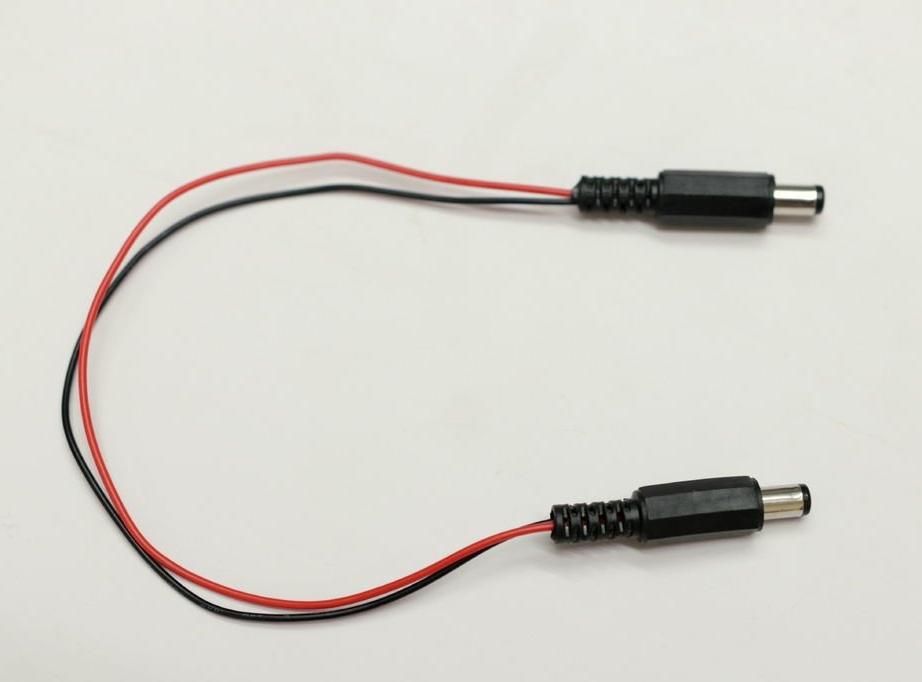
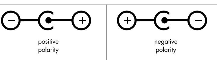
Now you need to prepare the adapter for connecting the UPS output to the router input. At this stage, it is extremely important to determine the polarity of the connector, in some cases on these connectors, plus inside, minus outside, in others - vice versa. You can find out either next to the socket, or on the label, or on the power supply of this device. As a rule, they indicate everywhere.
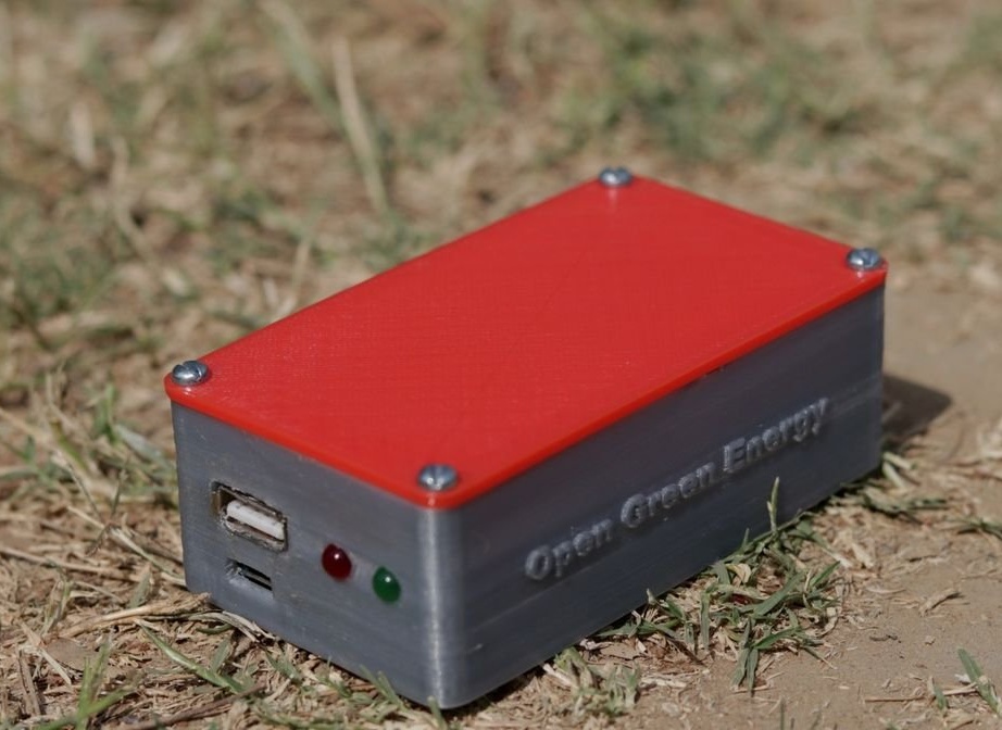
Step 9: Housing
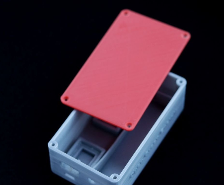
To give an attractive look to the product, the author developed a case for this project. For this, the Autodesk Fusion 360 program was used.
The housing consists of two parts:
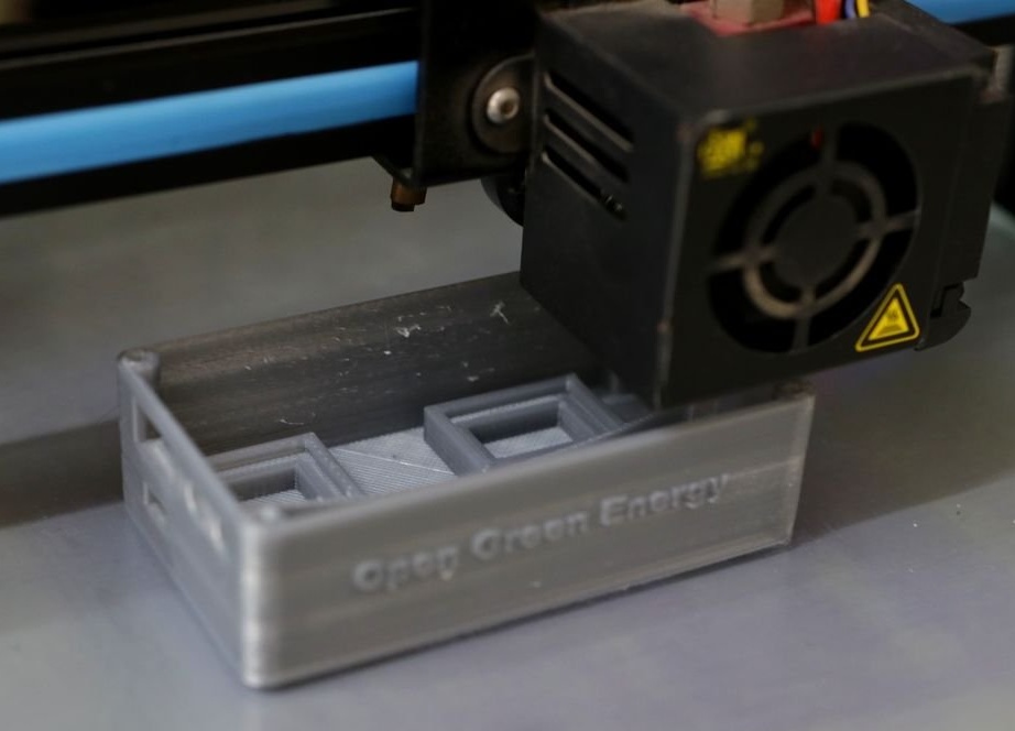
1. The main body
2. Cover
The main body is designed for all components, including the battery. The cover should cover the main body.
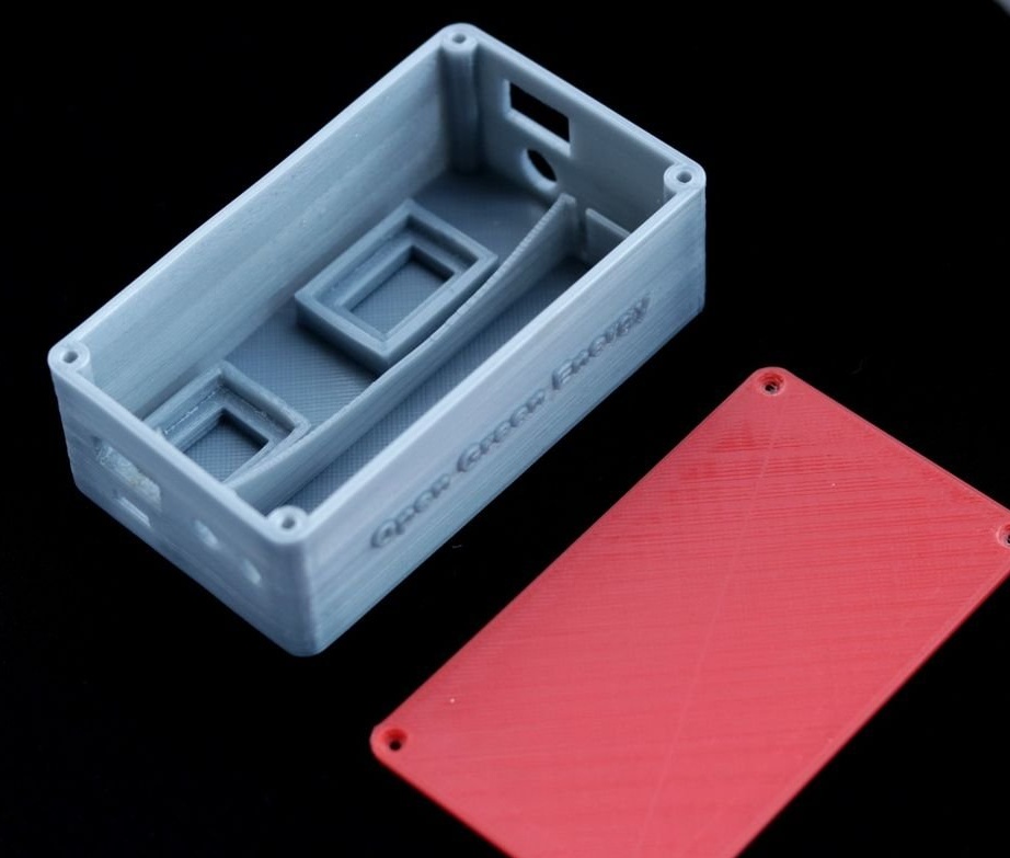
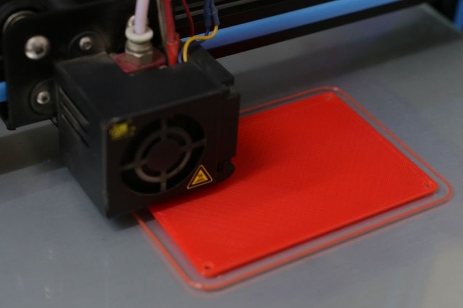
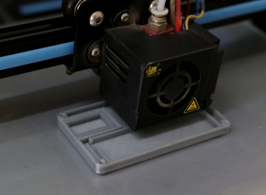
The author used his Creality CR-10S printer and PLA 1.75 mm gray and red plastic for printing parts. It took about 5 hours to print the main body, and about 1 hour to print the top cover.
The following settings were used:
Print speed: 60mm / s
Layer height: 0.2 mm (0.3 also works well)
Density: 25%
Extruder temperature: 200 degrees C
Table temperature: 60 degrees C
Files for printing can be downloaded at the end of the article.
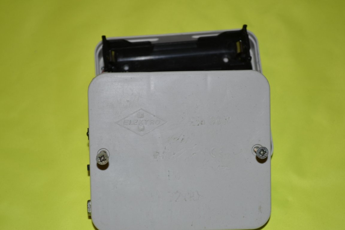
Push. For the project, the cheapest 20-ruble mounting box is perfect, the 18650 battery with a holder is placed in it like that, if that's what they were made for. Checked.
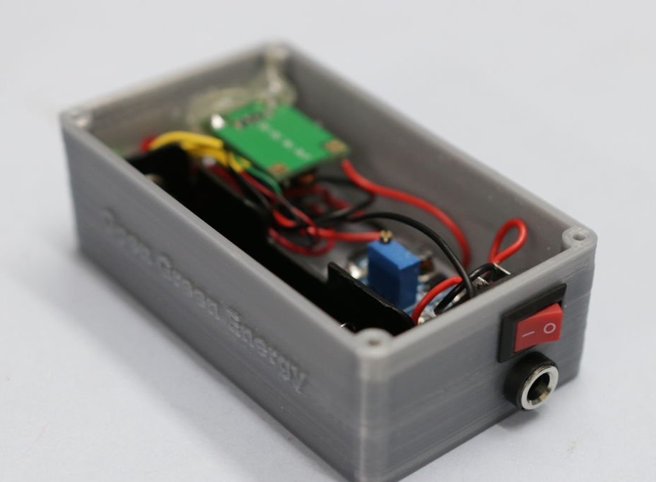
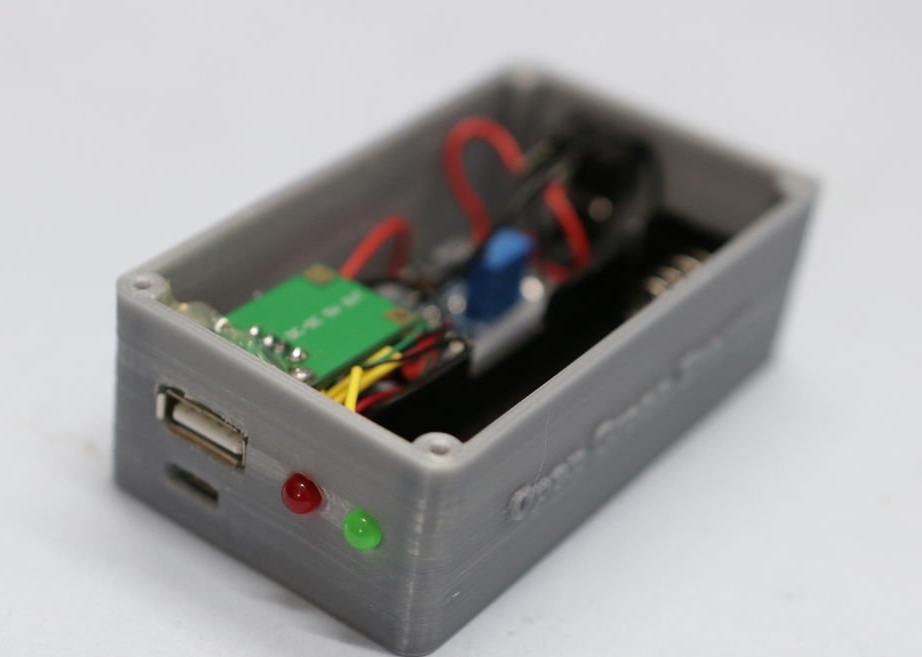
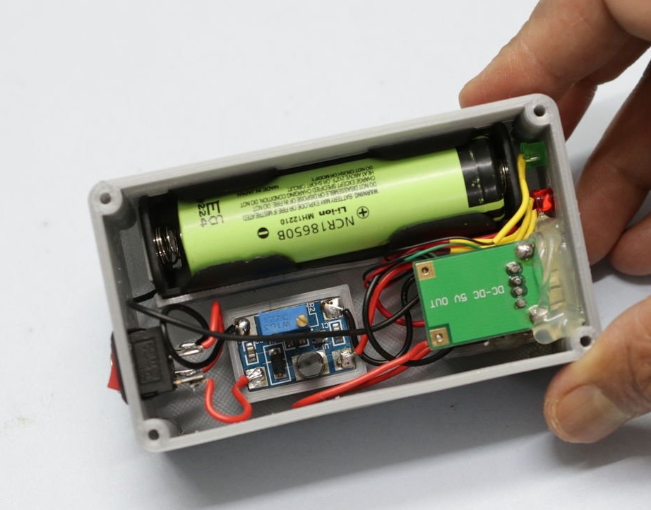
Step 10: Installing Components
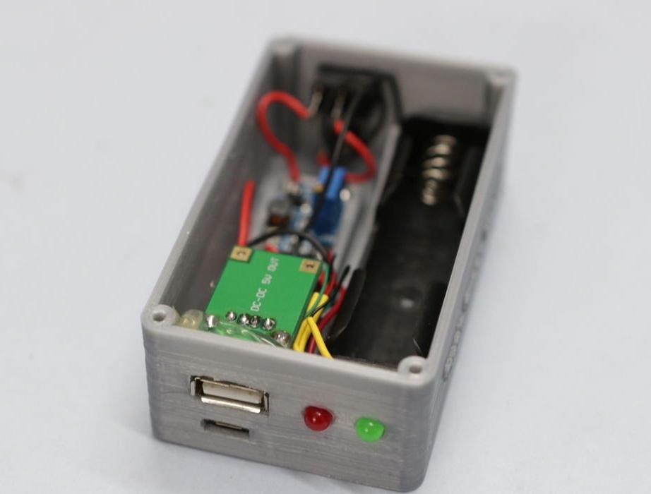
Insert the components (TP4056, step-up converters, LEDs, toggle switch and socket) into the holes of the main body as shown.
Finally, insert the 18650 battery inside the holder. Be sure to insert it with the correct polarity. Polarity is marked on the battery holder.
Finally, install the top cover and fasten to the 4 screws in the corners.
Step 11: Testing and Conclusion
Connect the UPS to a standard micro USB charger (5 V / 1 A). During the charging process, the red LED will light up, and when charging is complete, it will go out and the green will light.
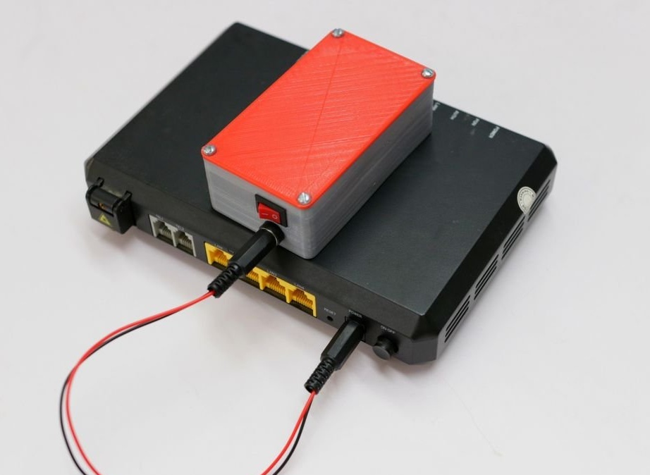
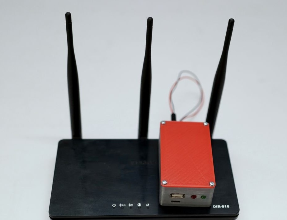
Now connect the mini-UPS to the router using the manufactured cable. The router should turn on.
When connected to the USB port of the smartphone, charging should begin on it.
In conclusion, a little on my own. The battery must be selected not only by capacity, but also by current output. The author did not take this into account.To simultaneously power the router and charge the phone, you need a battery with a current output of at least 3 A in this case, on batteries, the current output is marked with the letter C (3C - 3 amperes, 10C - 10 amperes). Keep this in mind if you decide to repeat. The same goes for the boost converter. For example, the Mt3608 converter is designed for a maximum load of 2A, when connecting a larger load, it is necessary to use more powerful modules, respectively.
Download files for 3D printing
That's all, good luck to everyone in your work!