
In this article, you’ll learn how Roman, the author of YouTube’s Open Frime TV channel, do it yourself assembled a flyback power supply on a UC3842 chip, and also we will understand together all the intricacies of the circuit.
The author began his journey in the development of power supplies with push-pull circuits, since they are easier to understand, and in single-cycle ones, the gap and other nonsense always frightened him. Well, the author has reached a moment of understanding and is now ready to share it with us. So let's get started.
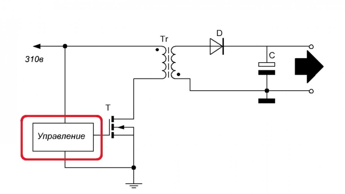
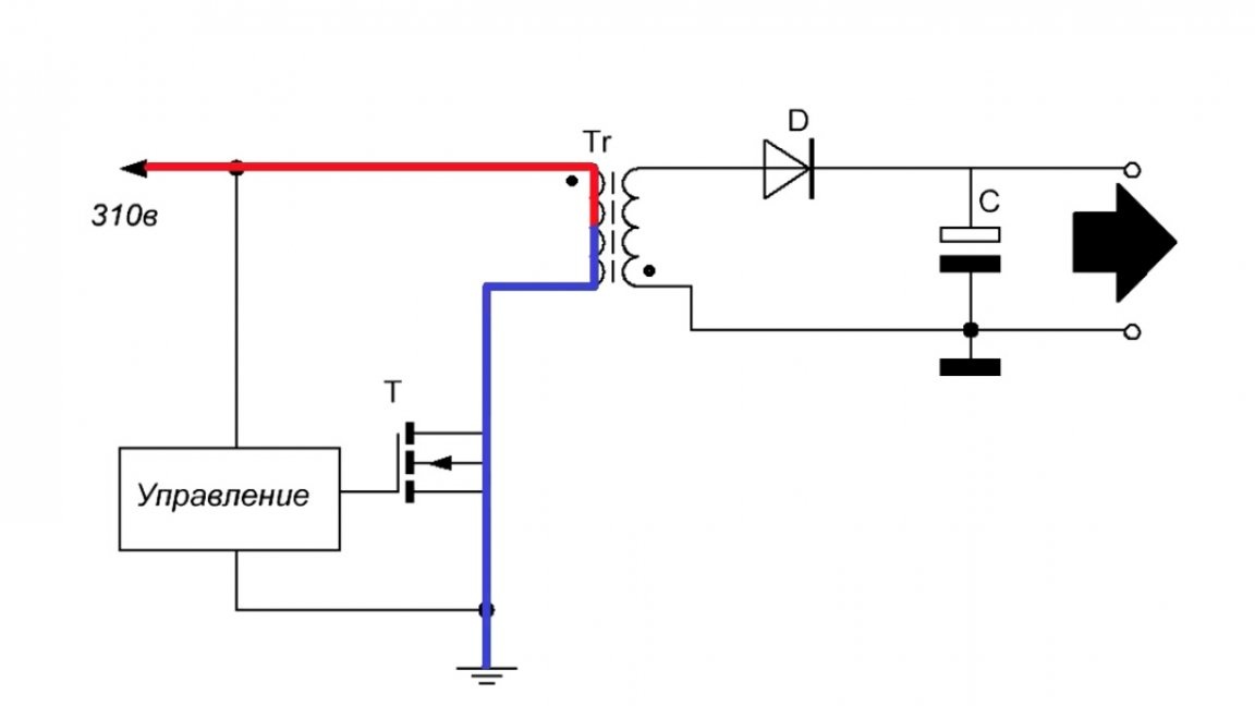
And we will start from the very beginning, i.e. directly from the principle of operation of the back-running converter. At first glance, there is nothing complicated, just 1 transistor, control circuit and transformer.
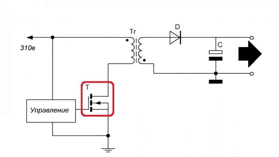
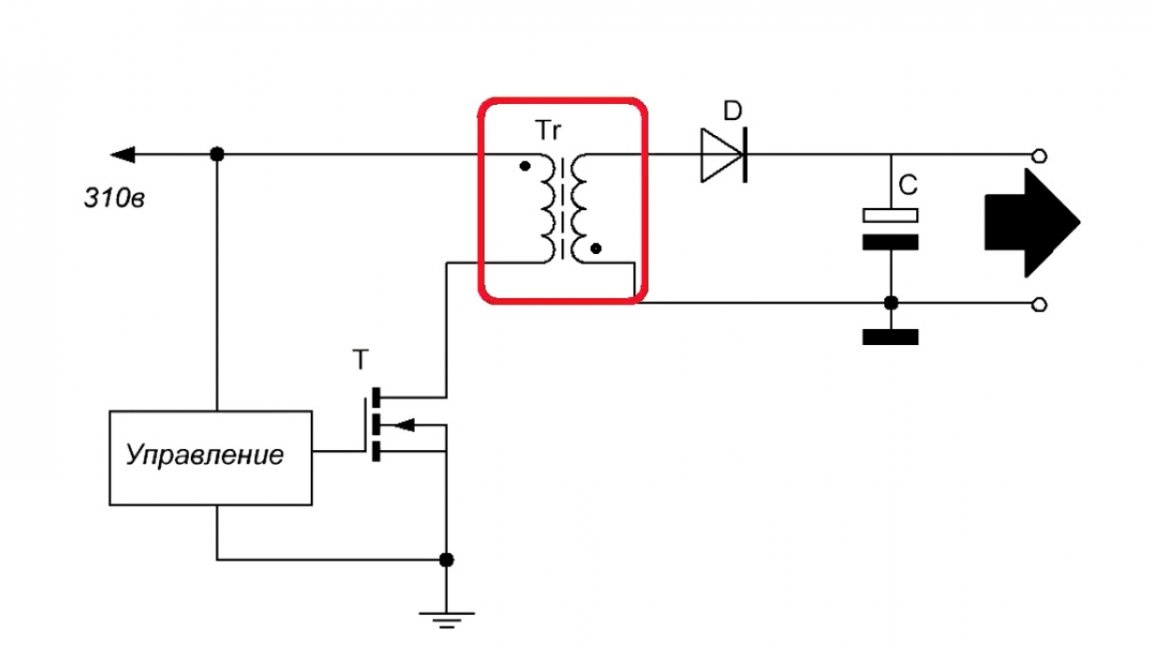
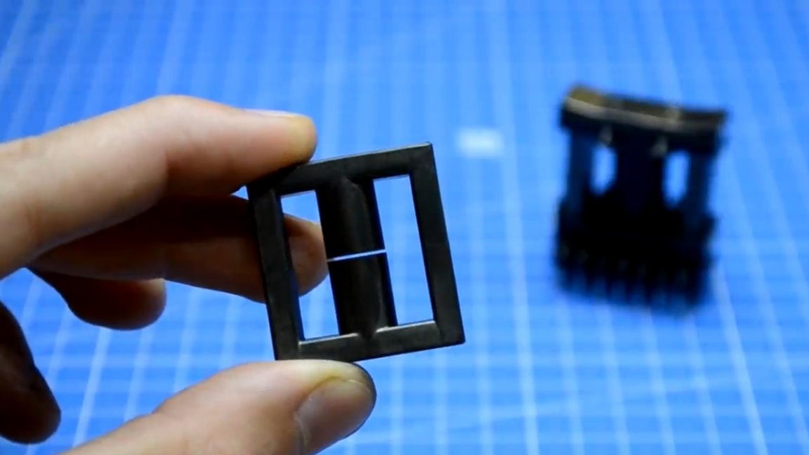
But if you take a closer look, you can see that the direction of the windings of the transformer is different and in general it is not a transformer at all, but a choke, in which there is the same gap, which was mentioned above, we will talk about it later.
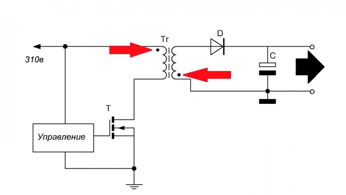
The principle of operation of this power supply is as follows: when the transistor opens and passes the voltage to the winding, the inductor stores energy.
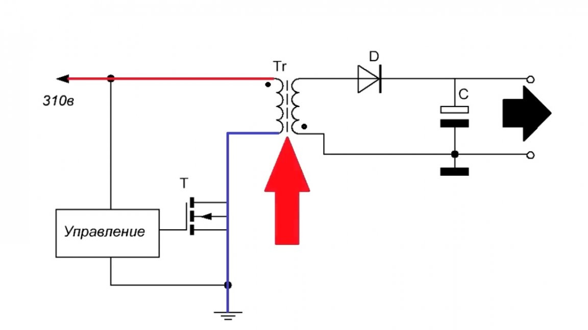
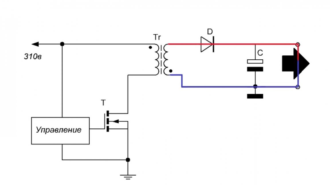
In the secondary circuit, current does not flow, since the diode is turned on in the opposite direction, this moment is called forward motion. At the next point in time, the transistor closes and the current through the primary winding no longer flows, but due to the fact that the inductor has accumulated energy, it begins to give it to the load. This is because the self-induction voltage has a different polarity sign and the diode turns on in the forward direction.
Now it’s time to talk about why the gap is actually needed. The fact is that ferrite has a very large inductance and if there is no gap, then it will not transfer all the energy to the load on the return stroke, and when the next transistor opens, the inductor will become saturated and become just a piece of metal, and in this case the transistor will work in short circuit mode.
Now let's look directly at the scheme of our future device.
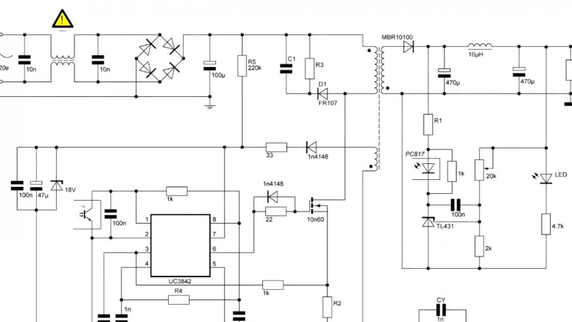
As you can see, this is a fairly popular circuit on the UC3842 chip.
There is nothing new in this scheme - everything is standard in it. Most likely, such a circuit has come across to you on the Internet more than once, since this circuit is the most stable, since we bypass the internal error amplifier (tl431) at the output of the block.
Also on the diagram there are no ratings of some elements, this is due to the fact that they need to be calculated specifically for your needs and conditions.
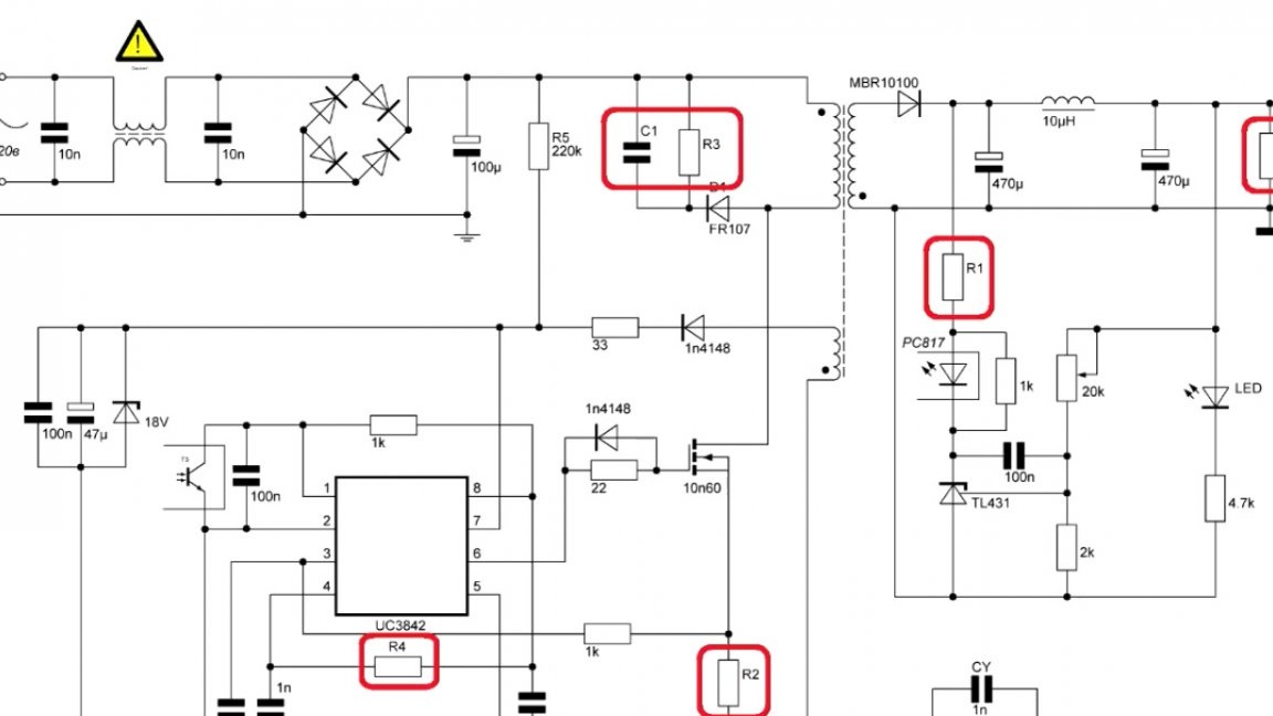
But you shouldn’t be scared, there’s nothing complicated, the whole calculation is easy and is done in a semi-automatic mode, so even a beginner can handle it.
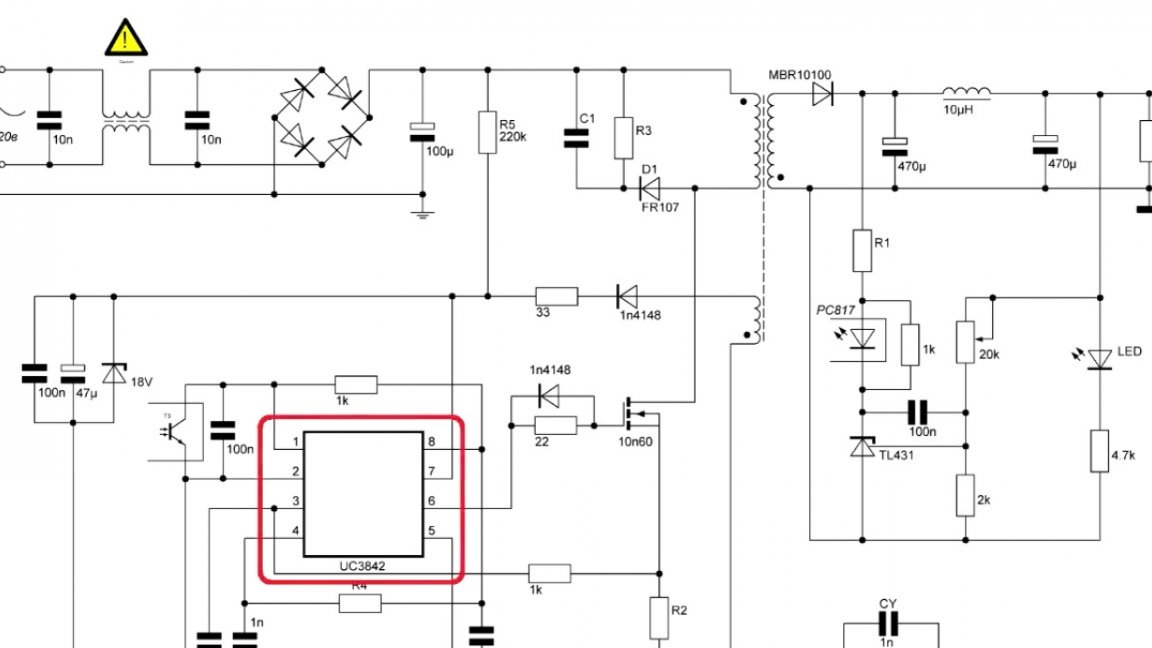
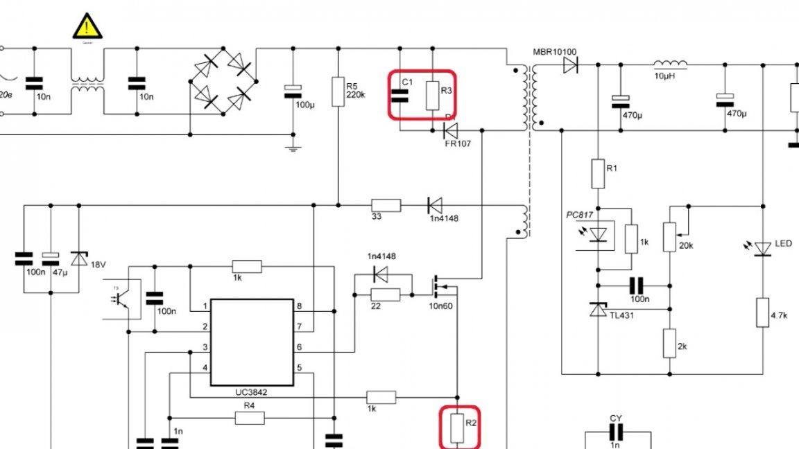
In the figure below, elements (R2, R3 and C1) are highlighted in red, which are calculated in the Starichka program, details are given before winding the transformer.
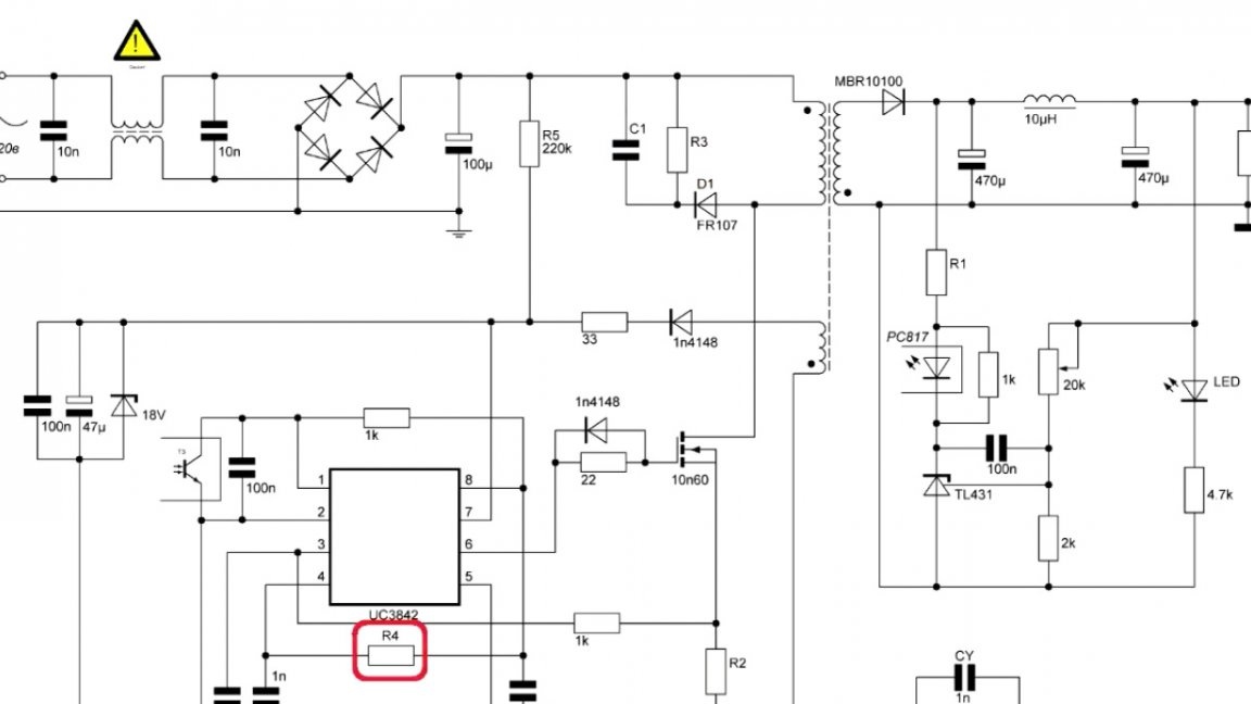
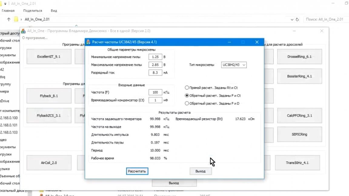
Resistor R4 is calculated for a specific frequency, also a special computer program. It is present in the software package for this scheme, you can download HERE or in the description under the original video of the author, the link "SOURCE" at the end of the article.
The following chips are suitable for this homemade product: UC3842, UC3843, UC3844 and UC3845. The difference is that the frequency of the UC3844 and UC3845 microcircuits is divided by 2, while the UC3842 and UC3843 do not, so the maximum pulse value of the first two microcircuits is 50%, and the next two are 100%.
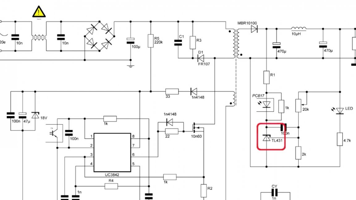
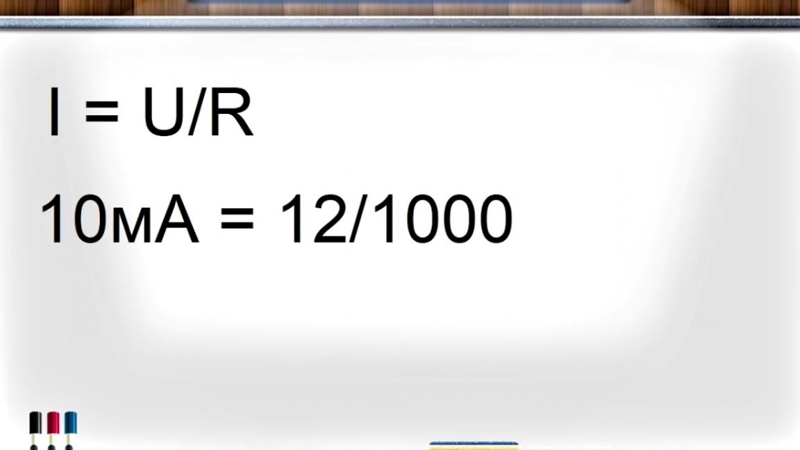
It will also be necessary to calculate the resistor limiting the current of the optocoupler, so that at a rated output voltage a current of 10 mA flows through the optocoupler.
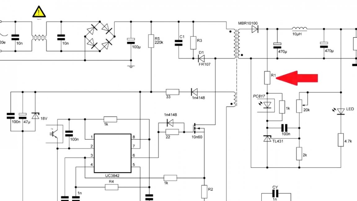

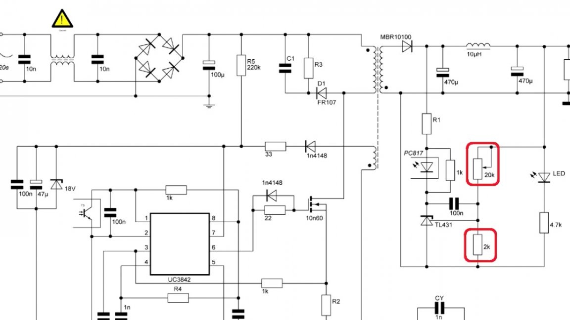
This power supply breaks into relay operation if there is no load at the output, so it is necessary to install a load resistor. At rated voltage, this resistor must dissipate 1W.
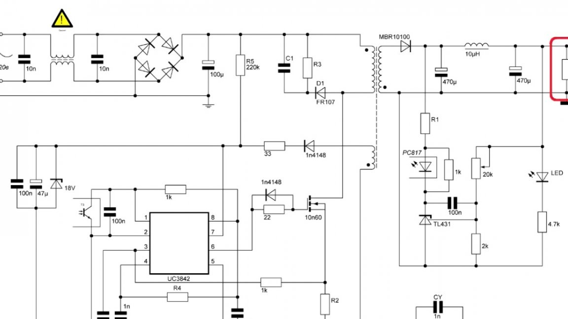
And the last thing we have is a rough adjustment of the variable resistor.
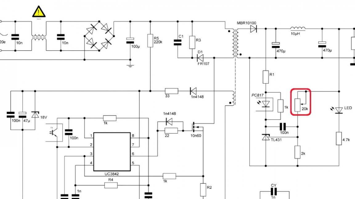
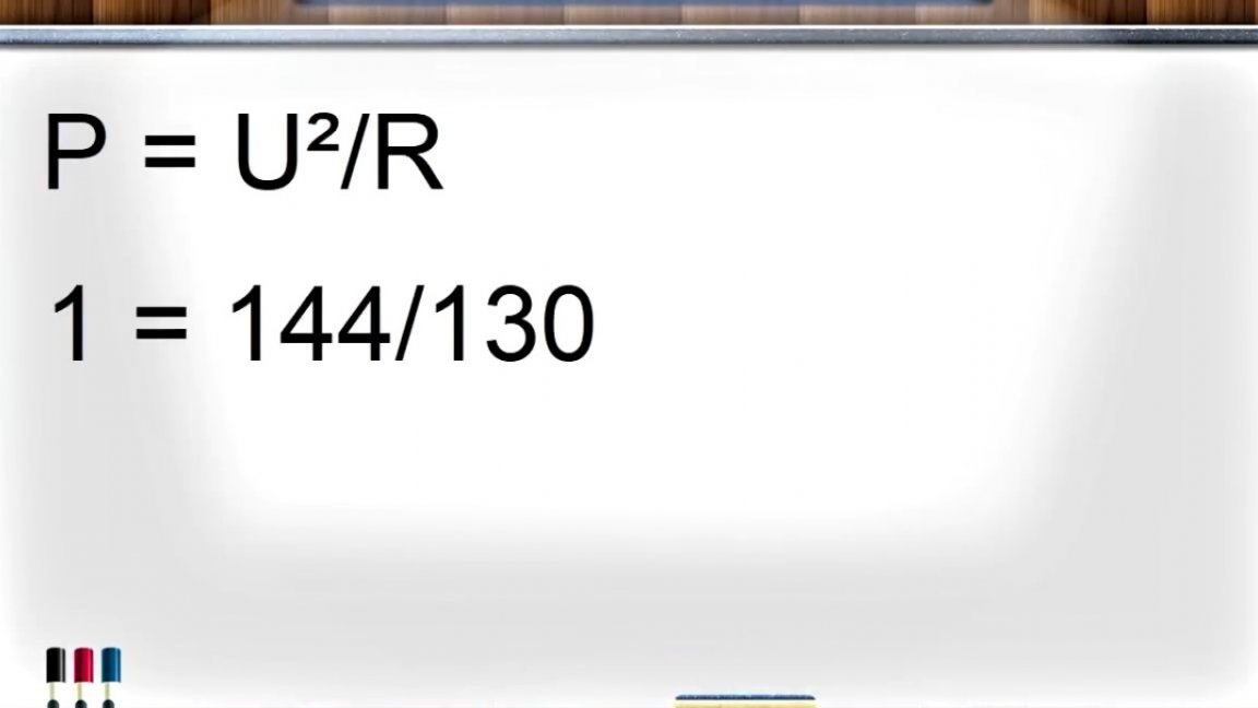
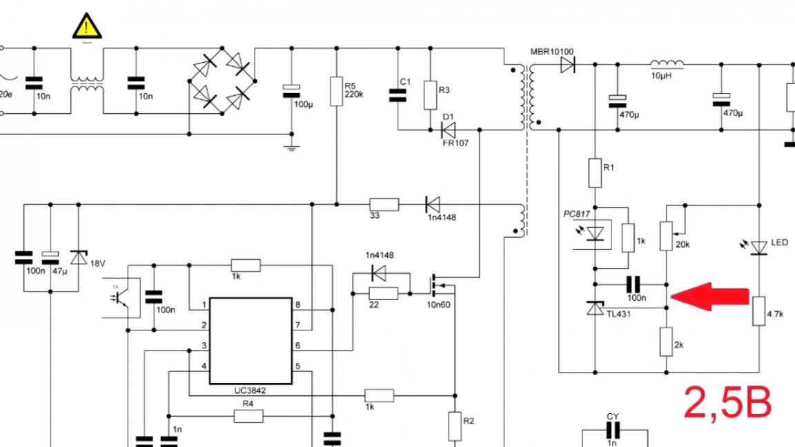
This variable resistor together with a constant creates a voltage divider, and at the rated voltage at the division point there should be a voltage equal to 2.5V.
Immediately before installing it on the board, the variable resistor must be unscrewed to approximately the desired resistance, using a multimeter.
Well, actually, the whole calculation. Now go to the printed circuit board.
As you can see, here the author tried to minimize everything as soon as possible, and in the end was satisfied with the result, although the wiring was not perfect.
In this example, the ETD29 transformer is used, but if you have another transformer available, just change the size of the transformer, and then copy the trace of the author board.
After the board was drawn, the author first made, so to speak, a model using the widely known LUT method.

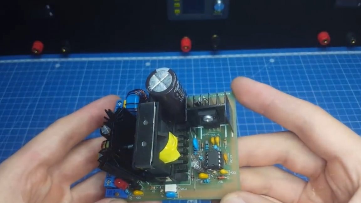
On this model, he tested everything, and then he ordered a fee from a Chinese company. And now, after a month, we finally have such scarves:
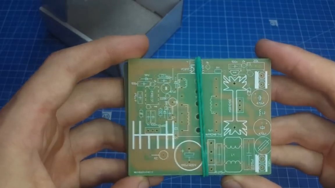
Now we proceed directly to sealing all the parts and components into place. Let's start with the frizz.
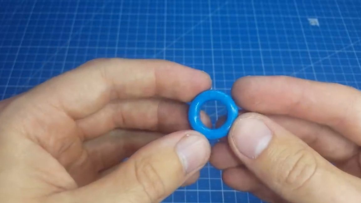
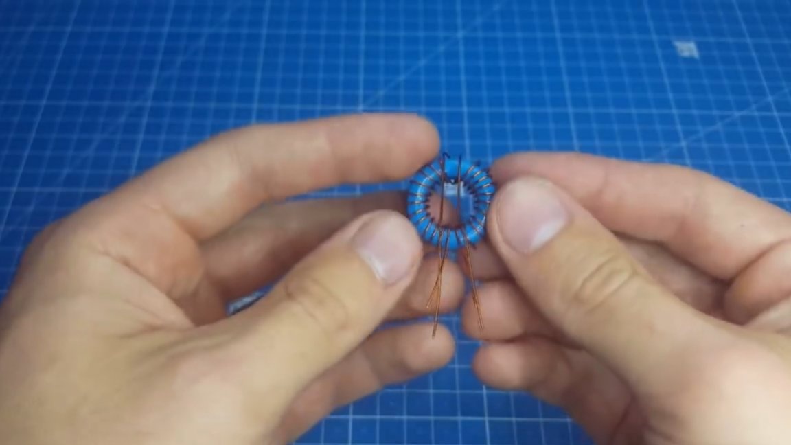
Now we have winding ahead. First, start small - input choke. A ferrite ring permeability of 2000-2200 is suitable for it. On this ring we wind 2 by 10 turns with a 0.5mm wire.
Further output choke. Its inductance should not be very large so as not to create unnecessary resonant oscillations. You can wind the output inductor both on a ring of powdered iron and on a ferrite rod. The author decided to wind on such a ring with a permeability of 52.
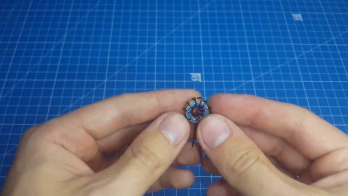
The whole winding consists of 10 turns of 0.8 mm wire. Well, now we have the most difficult part of today's homemade work - this is the winding of a power transformer-inductor.
Here, first of all, it is necessary to determine the voltage and current, there are some limitations, such as the maximum current should not exceed 3A without cooling and 4A with cooling, since for a larger current Schottky diodes need a radiator of a larger area.
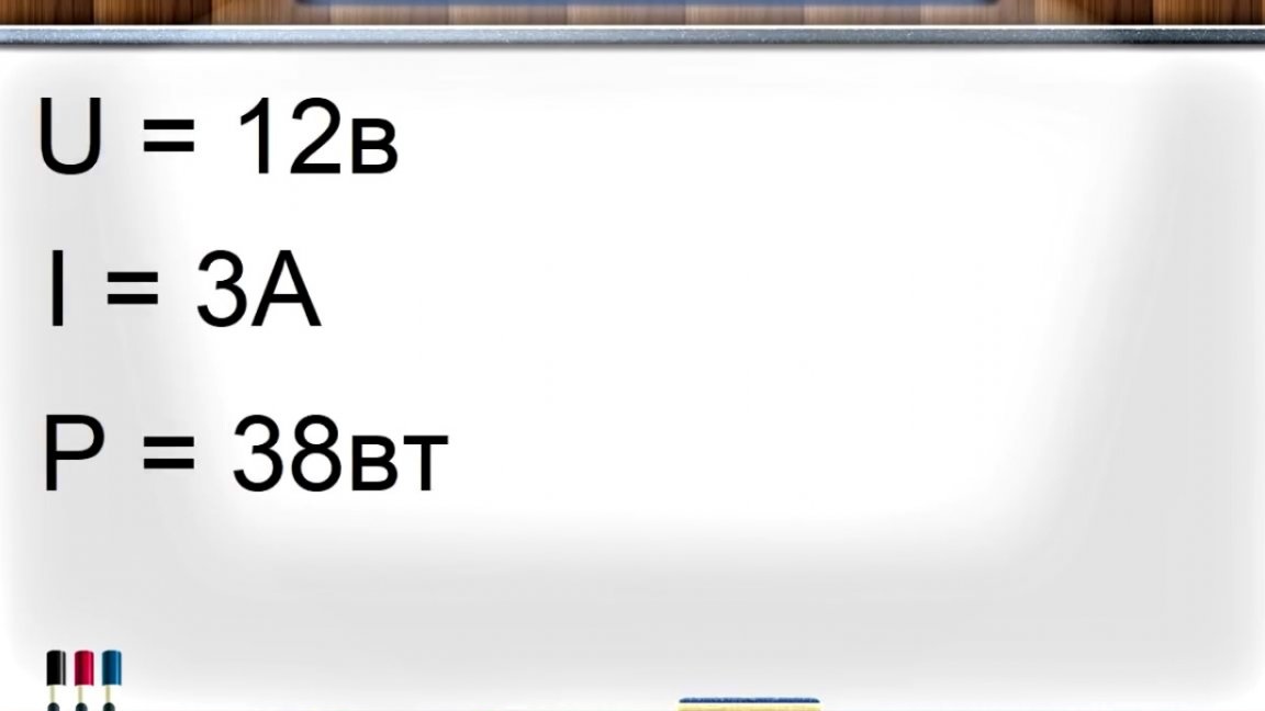
This implies a limitation of the output power, for example, with a voltage of 12V maximum power cannot exceed 48W, and with a voltage of 24V the power can already reach 100W.

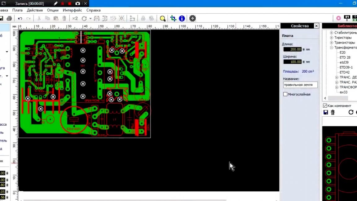
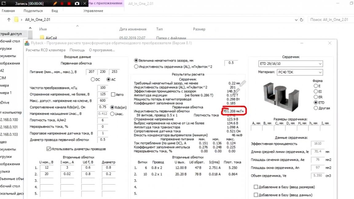
To calculate the transformers, the author recommends using the Starichka program. Below is the interface of this program.
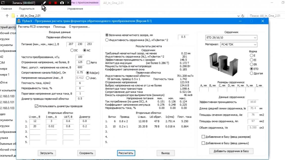
In the required fields we bring all the necessary parameters and we get the data for winding at the output, as well as the necessary core gap.
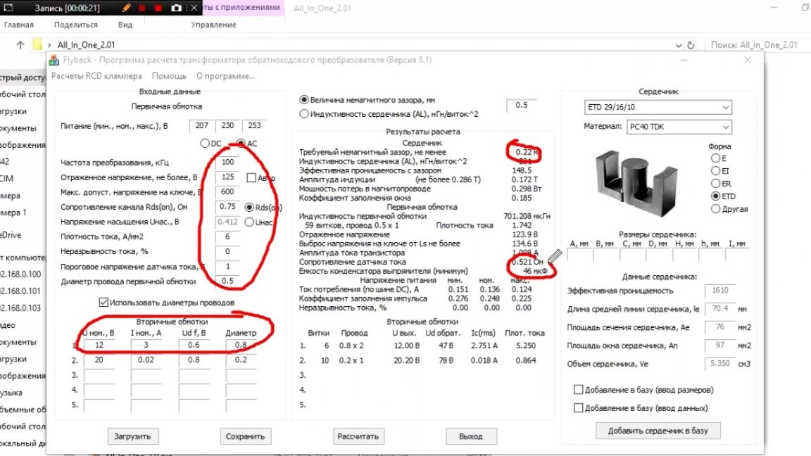
Also, in addition to this, the program calculated the resistance of the resistor R2 and the minimum value of the capacitance of the input capacitor C1.
As you can see, the author chose 20V for self-energization, so this is the most suitable value.
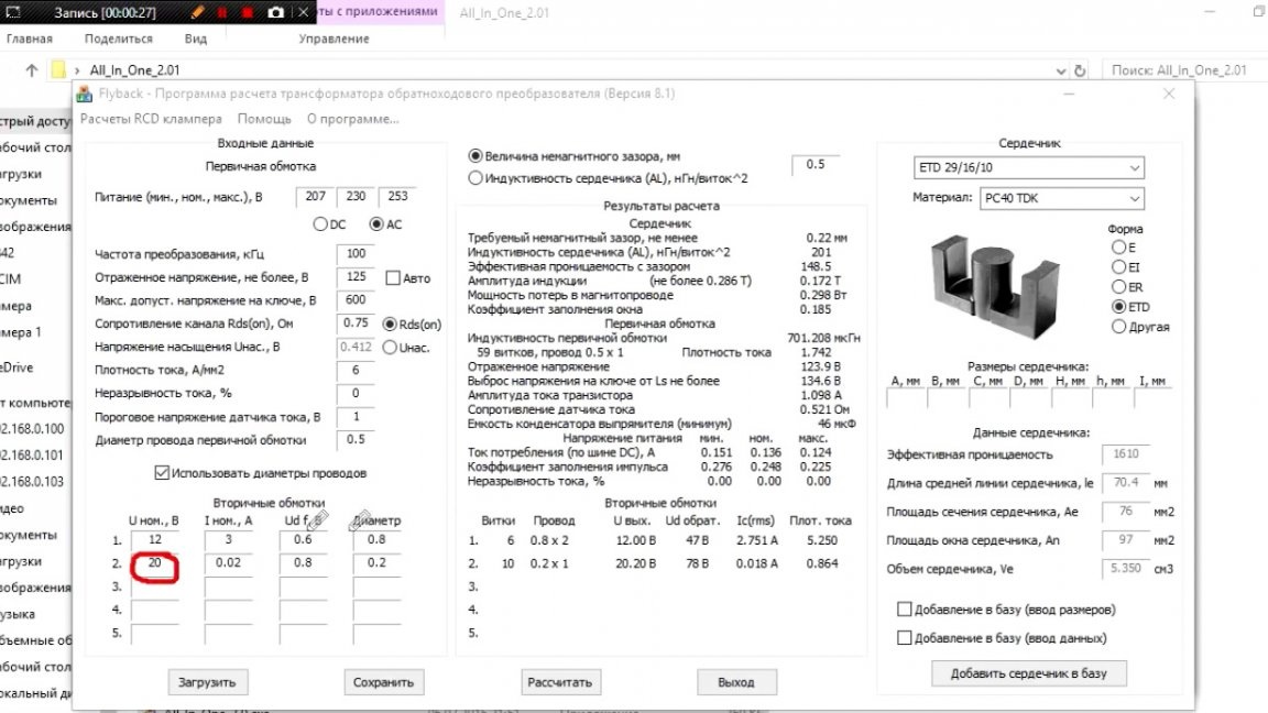
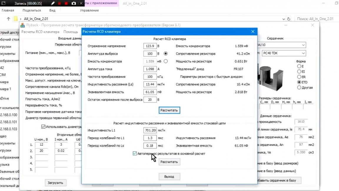
The author also notes that another advantage of this program is that it can calculate snubber parameters for us, which, you see, is very convenient.
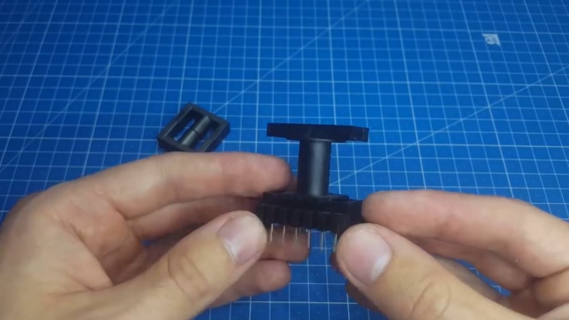
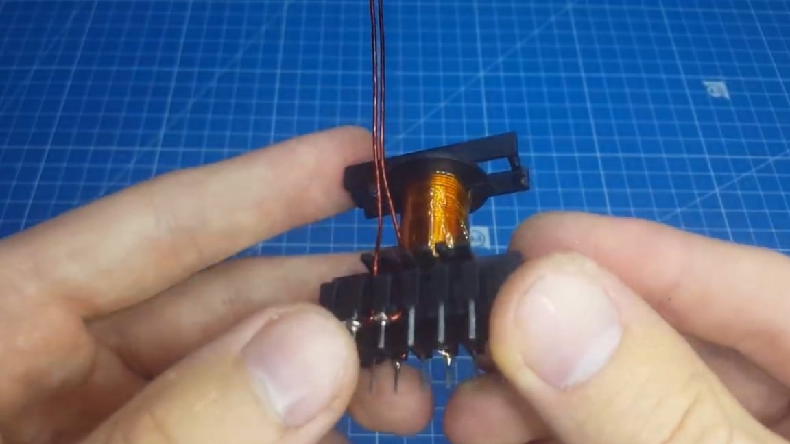
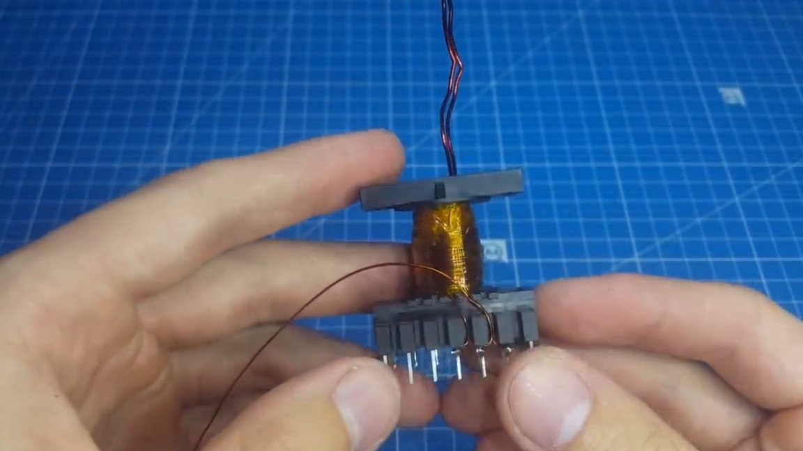
So, we proceed to winding the transformer. In order to make it easier for ourselves and not to go astray during the winding process, we wind all the windings in one direction. The start and end are shown on the circuit board.
The primary winding is divided into 2 parts, first half of the primary, then the secondary and another layer of the primary. Thus, the leakage inductance decreases and the flux linkage is increased.
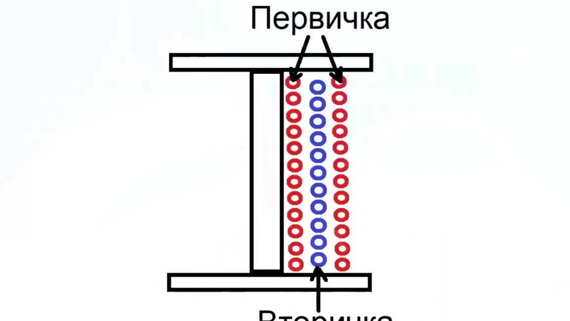
Last of all, we proceed to winding the self-winding winding, since it is not so important. An example of winding a transformer now in front of you:
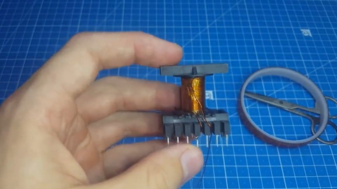
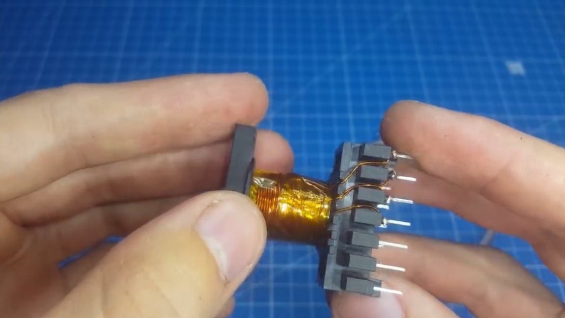
And almost everything is ready, it remains only to choose a gap or to buy a transformer with a ready gap, in fact, the author did this.
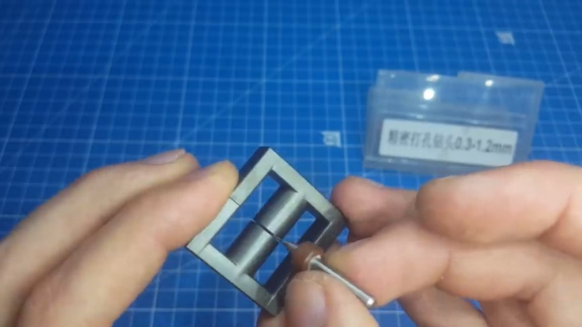
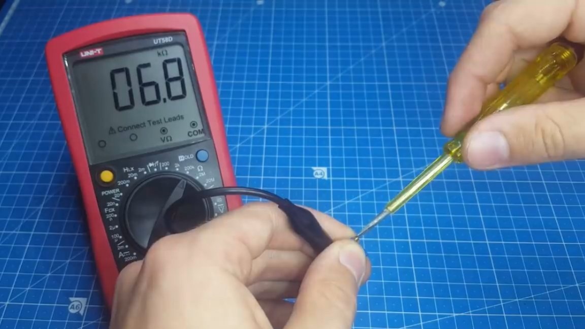
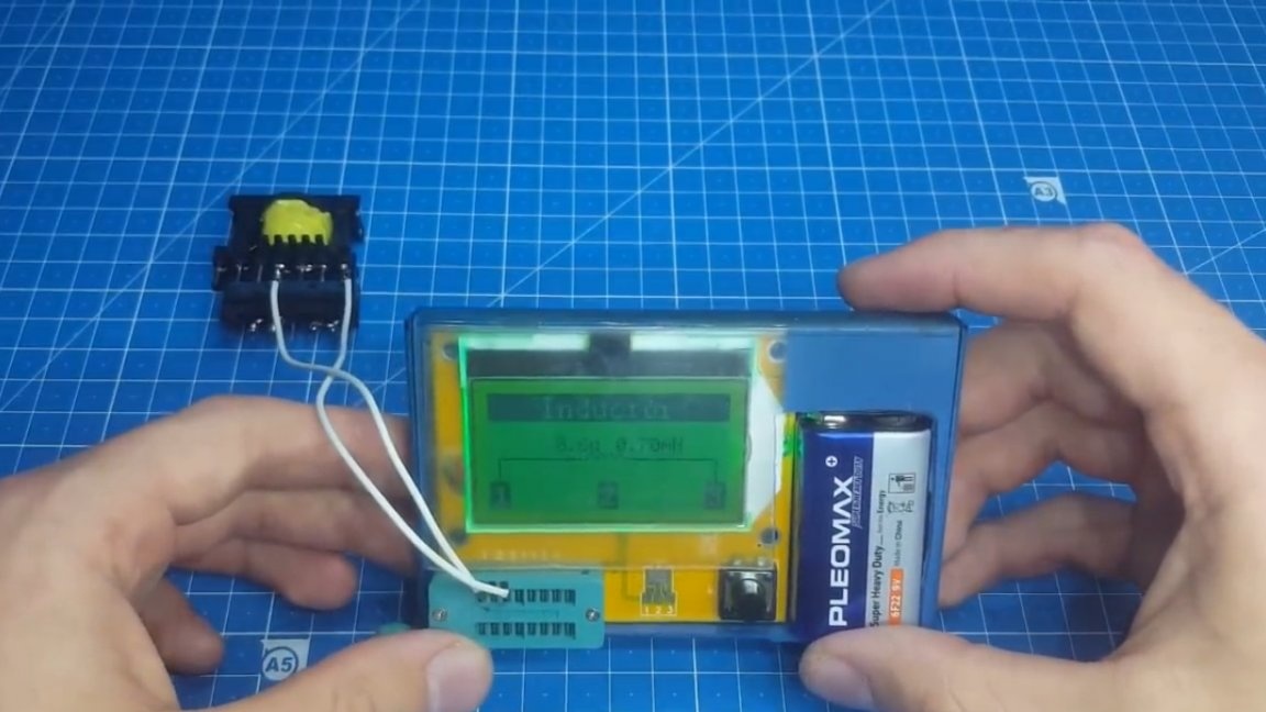
If you still had to select the gap, then at least some instrument measuring inductance should be at hand, for example, a multimeter with the function of measuring inductance.
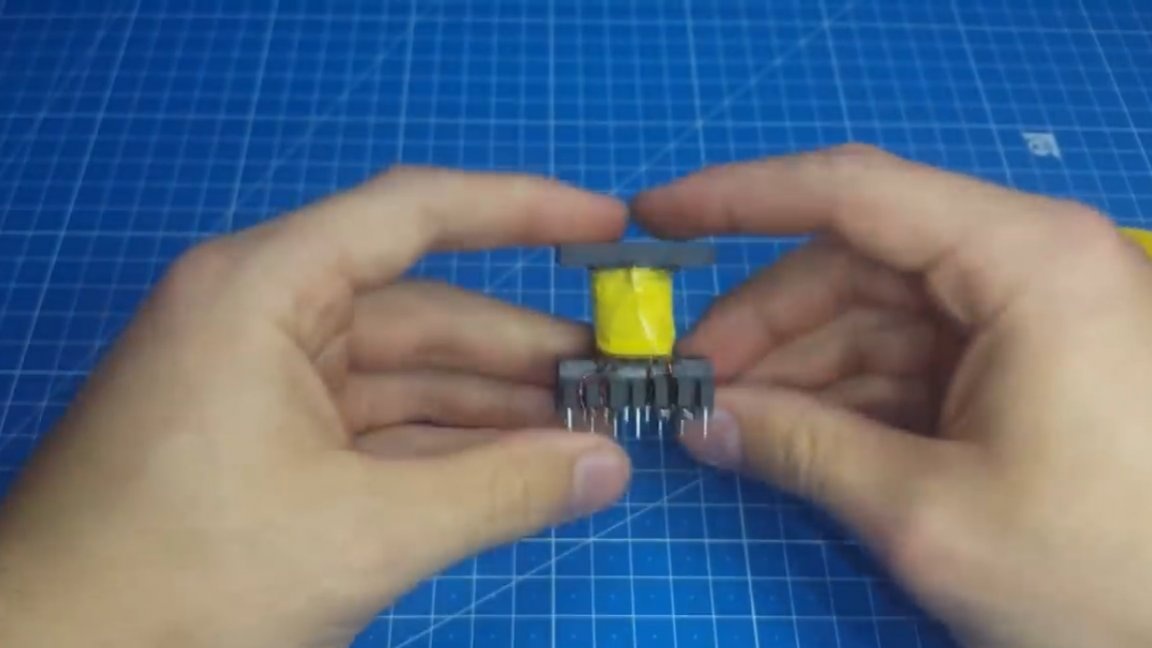
If the resulting inductance coincides with the calculated one (approximately), then our transformer is wound correctly and you can install it on the board.
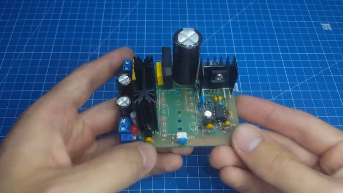
And in the end, as always, we’ll do a couple of tests.
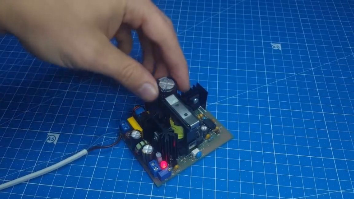
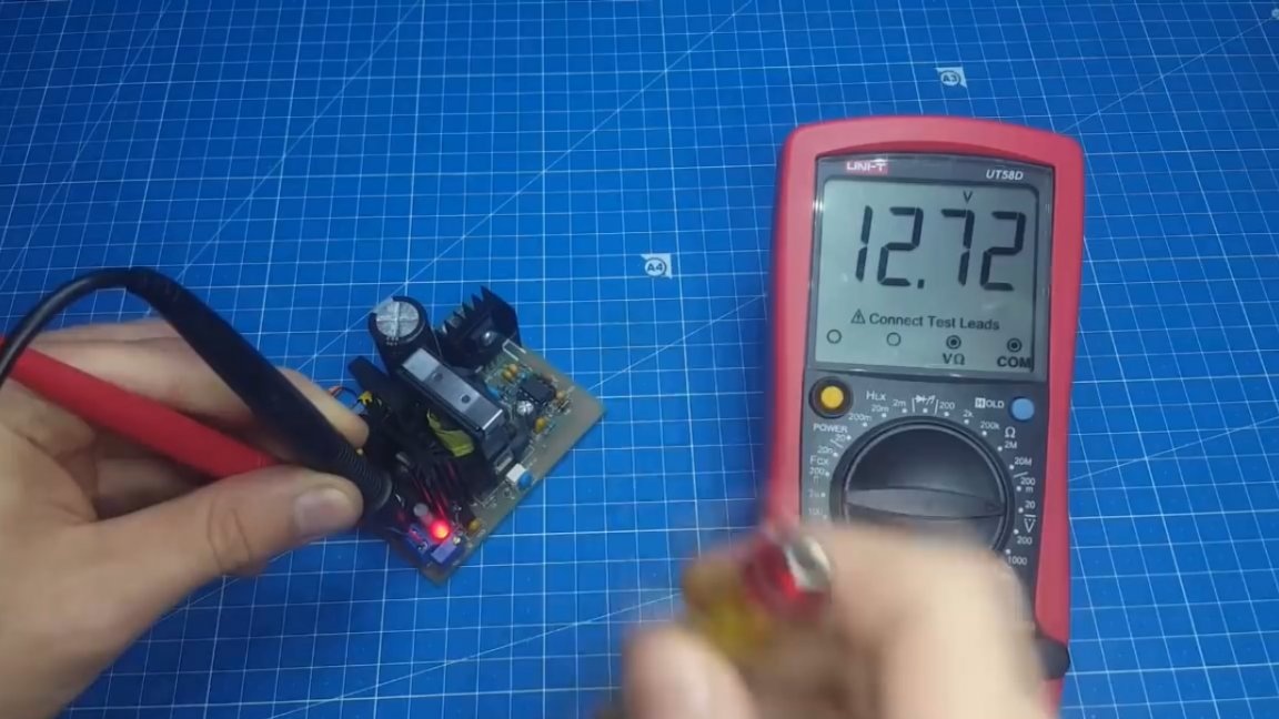
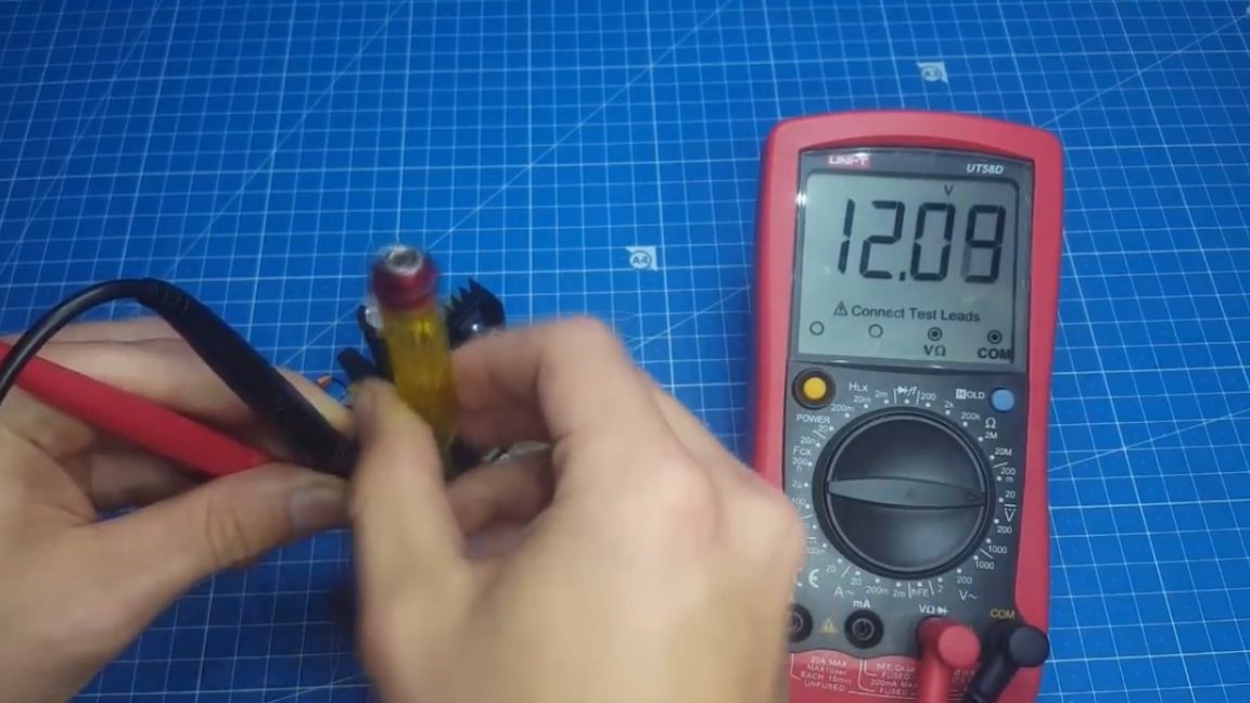
The LED lights up, the power supply starts up. The output voltage is a little more than 12V, but with the help of a tuning resistor, you can set a more accurate value.
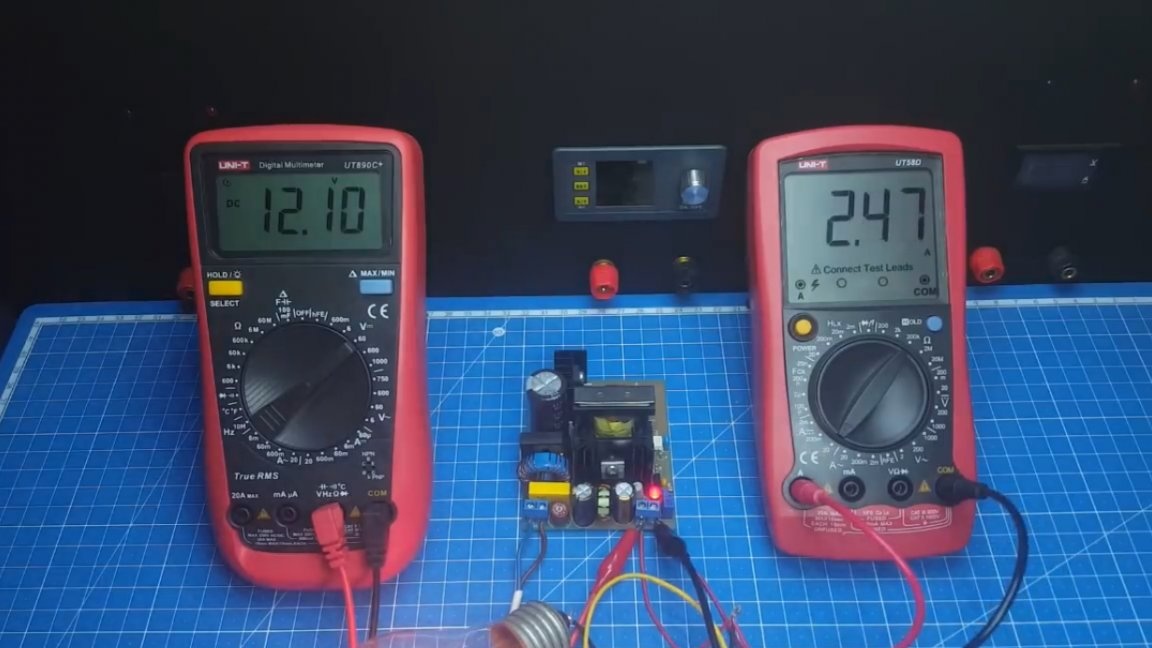
Our homemade power supply copes with a load test in the form of an incandescent lamp with a bang, and this means that we have turned out an excellent device.
That's all. Thank you for attention. See you soon!
Video: