
In this article, you will learn how to assemble one of the options for a good budget and quite powerful stereo sound amplifier with a timbral block, USB, Radio, as well as AUX. We will assemble a stereo amplifier from ready-made Chinese modules, so even a novice radio amateur will be able to repeat such a project.
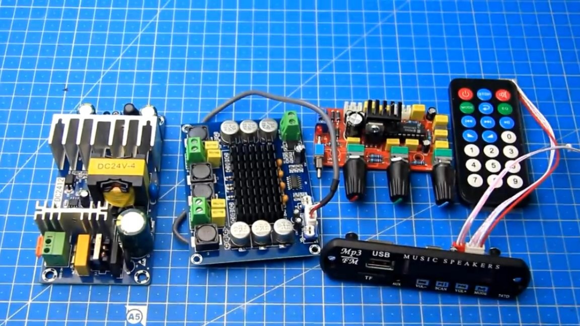
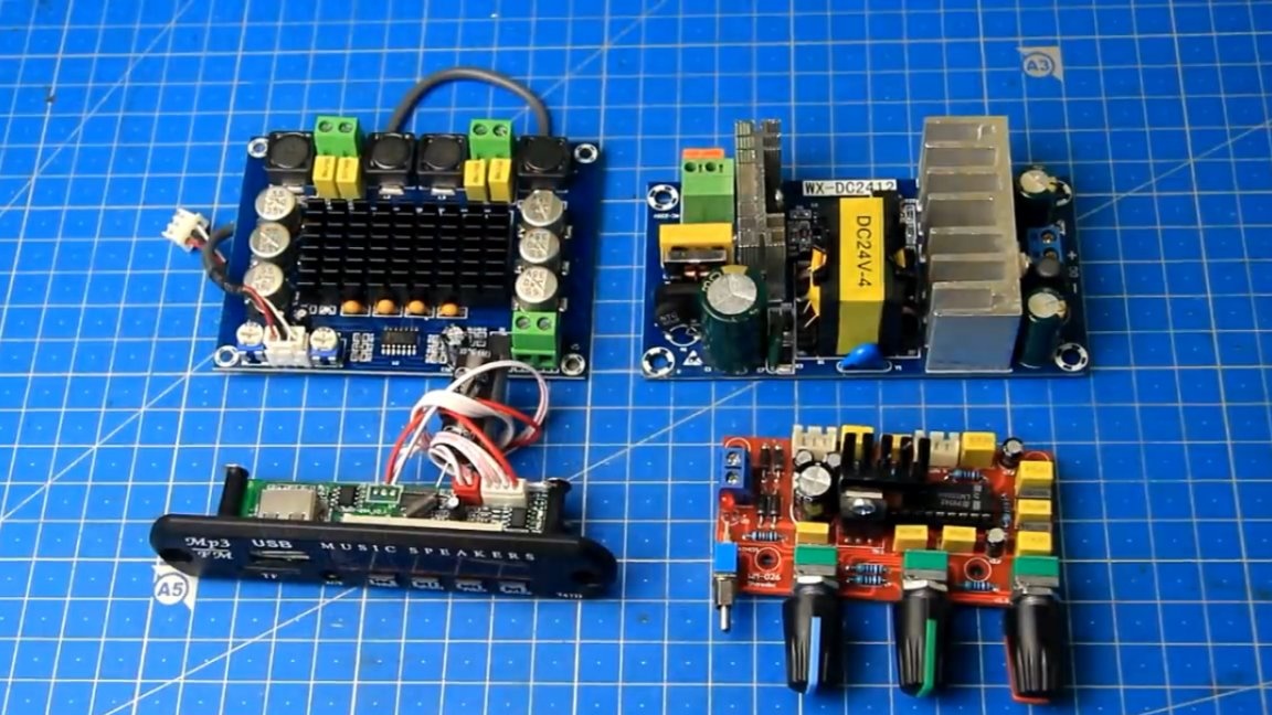
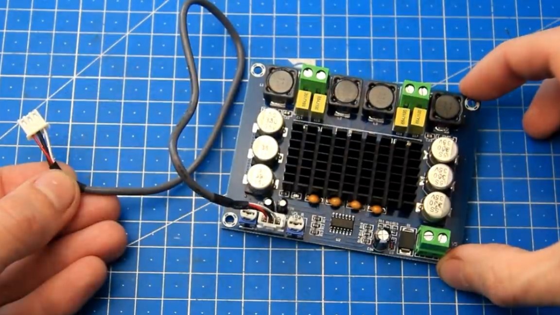
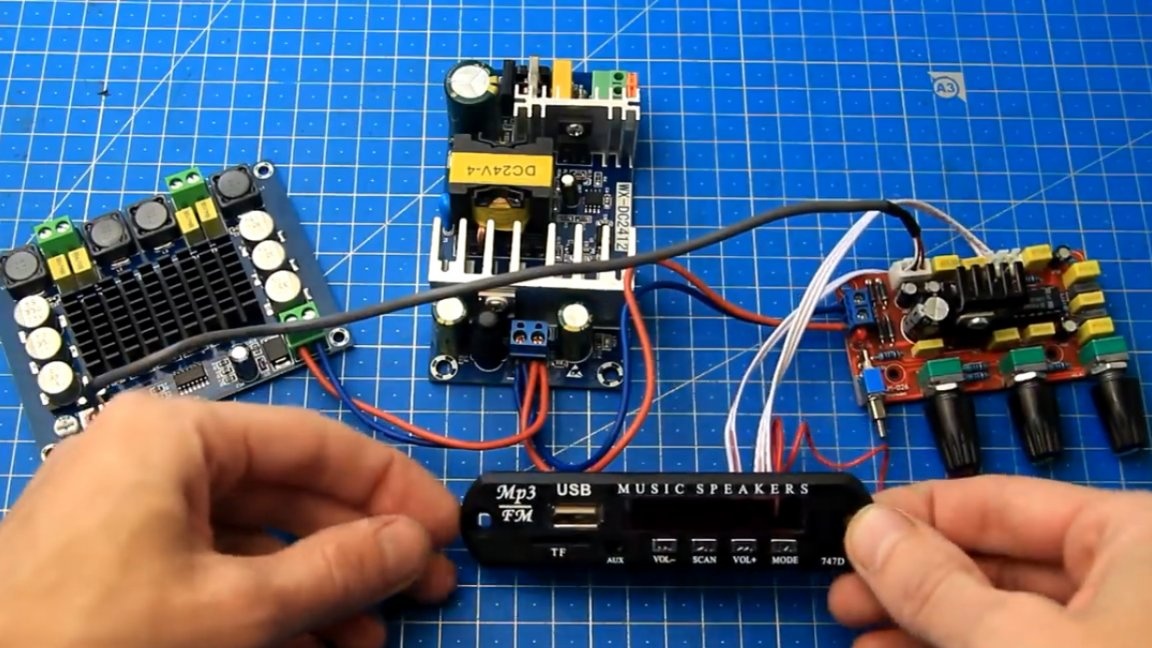
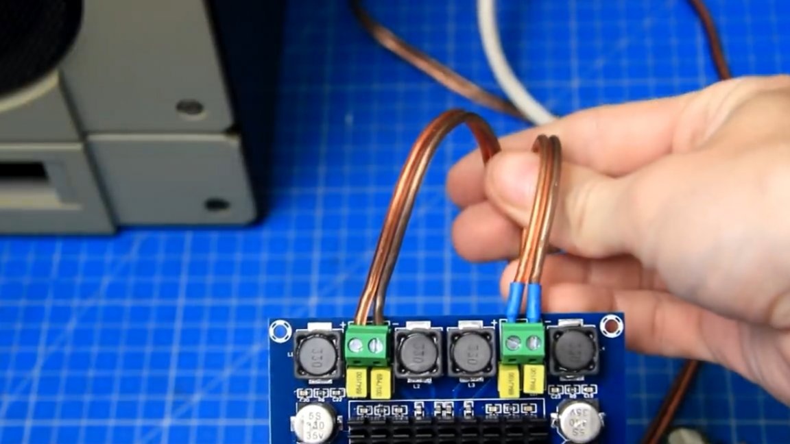
To build this amplifier, the author (YouTube channel "Radio-Lab") selected and purchased the following modules. Such an amplifier based on the TPA3116D2 chip will be responsible for amplifying the sound.
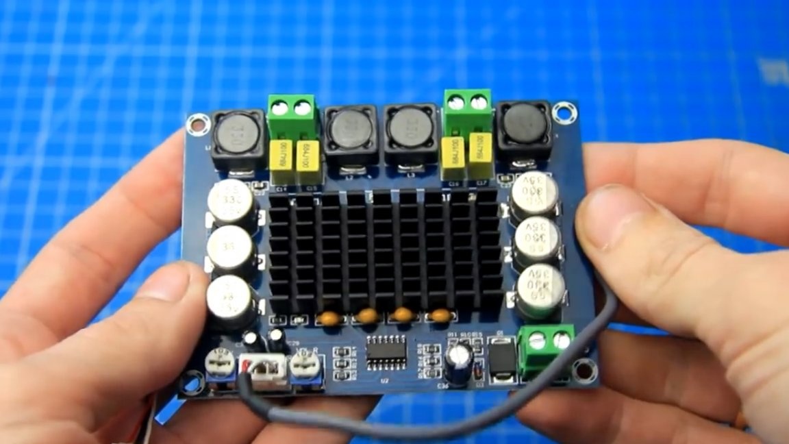
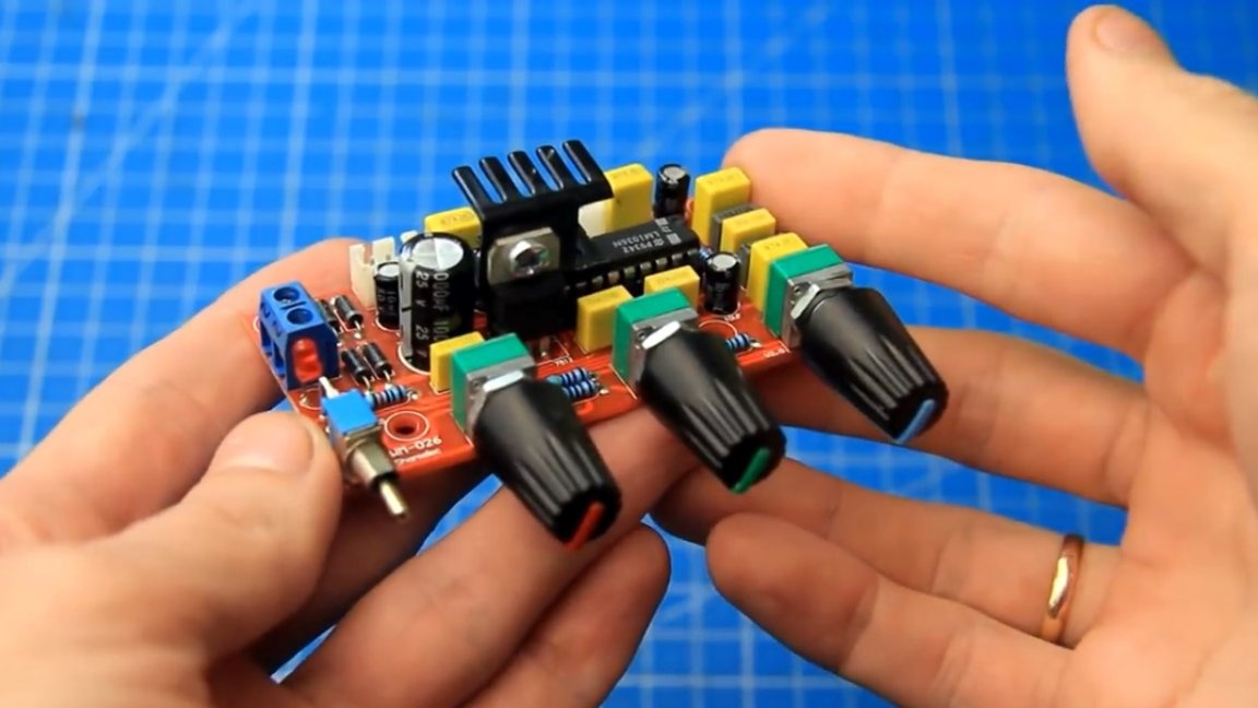
This amplifier is capable of delivering up to about 35W of power per channel with virtually no distortion at a 24V supply voltage. For adjusting the volume, low and high frequencies, such a timbral block on the widespread LM1036 chip will be responsible.
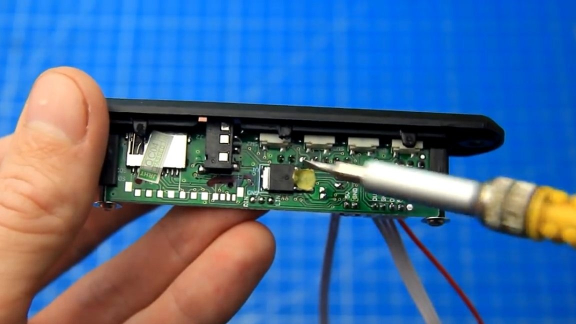
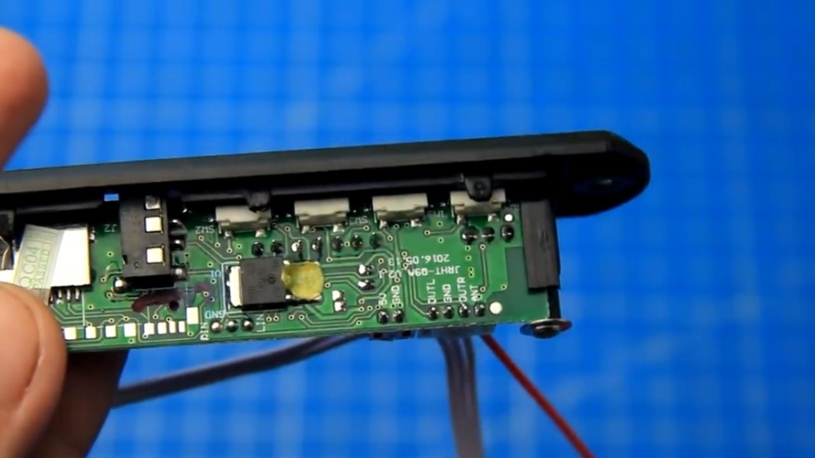
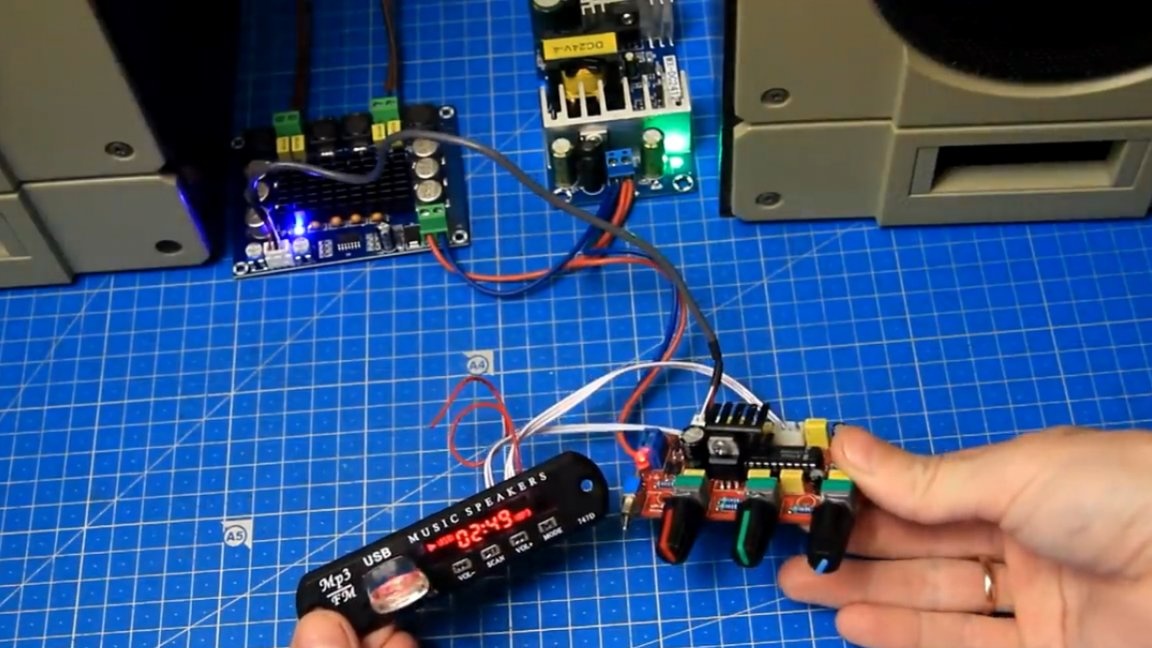
We will also use such a mortise sound module.

The module is quite simple, supports playback from USB media, also has a radio and is not deprived of a linear input. The mortise module version in this case is 12V, this can be seen by the presence on the board of a lowering 5-volt stabilizer 78M05.
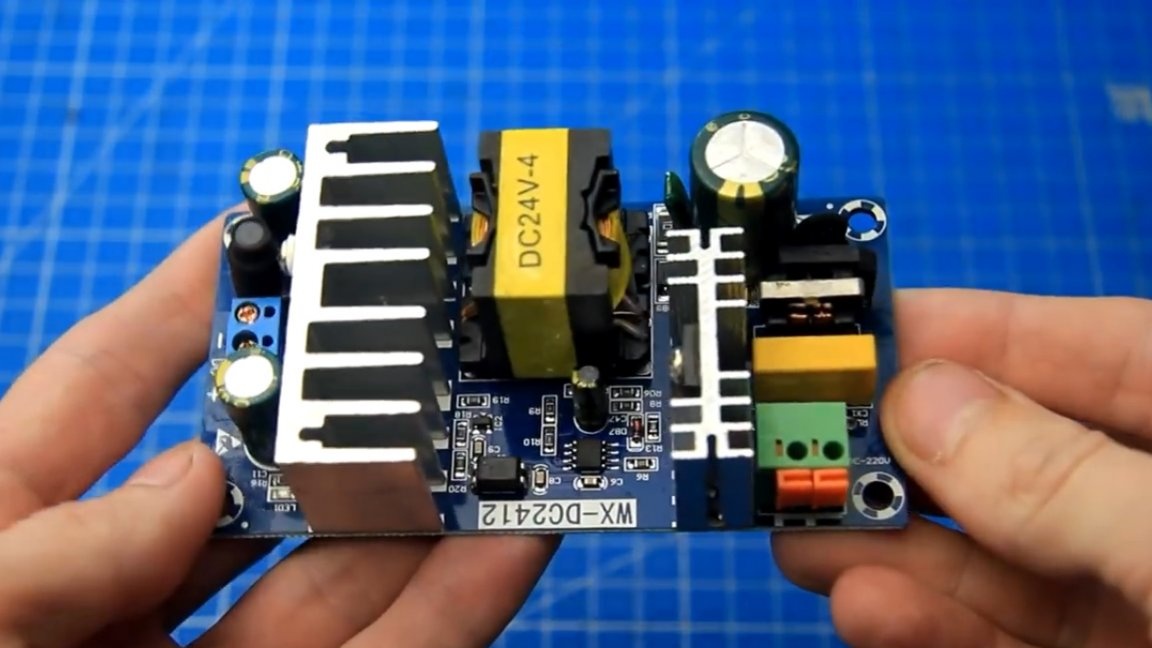
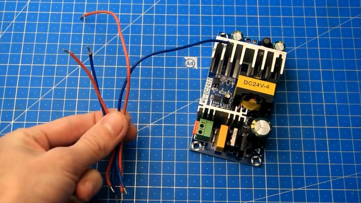
As a power source, we will use a pulsed power supply from an AC voltage of 220V with a voltage of 24V and a current of 4A.
The author selected all the modules so that they can be easily connected to each other. All modules have unipolar power and even a novice ham radio can repeat this project.
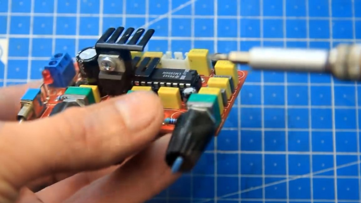
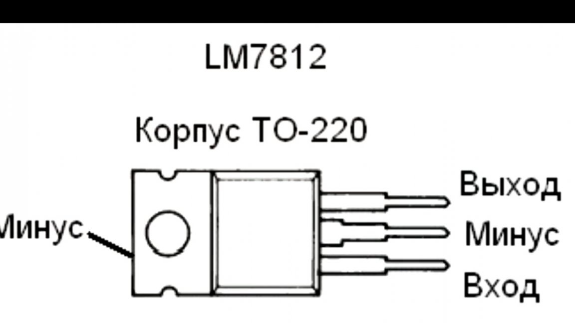
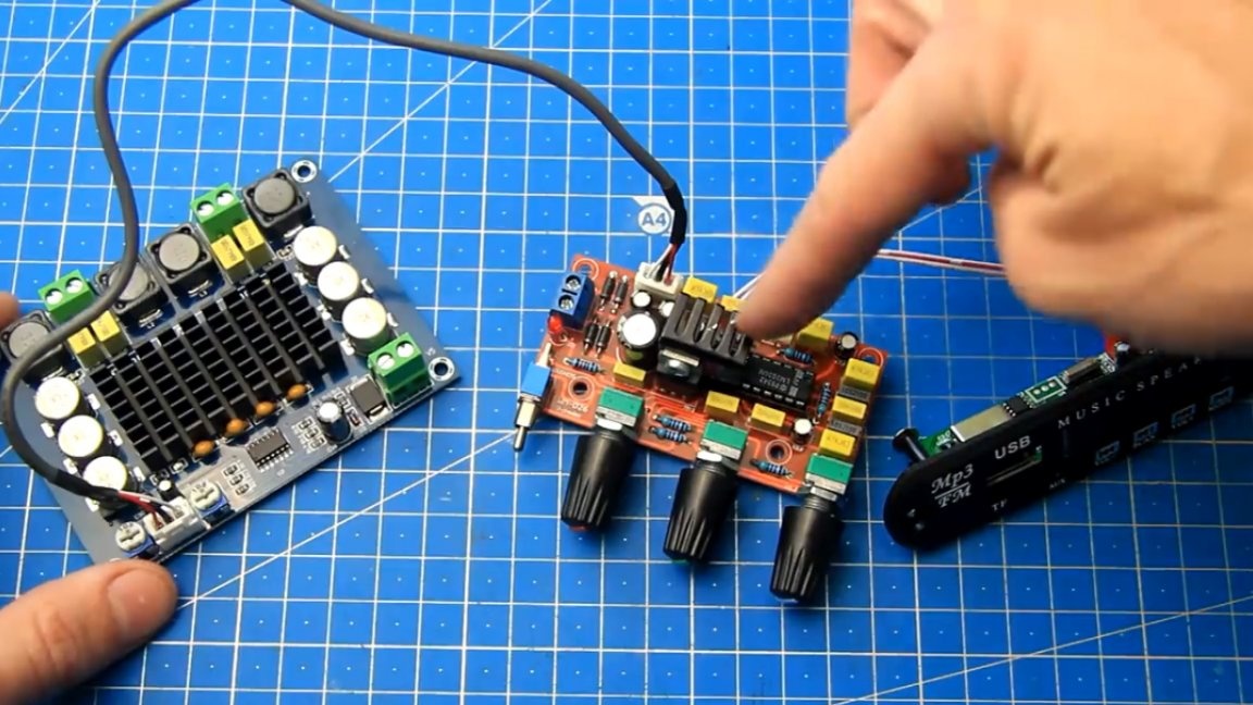
The connection diagram will be further closer to the test inclusion, as also not always everything is obtained the first time. Now let's get all the components together. Let's start by connecting the mortise module to the timbral unit, it’s just more convenient. There is a L7812 step-down stabilizer with a 12V output on the timbral block. It feeds the LM1036 chip, and you can also power the mortise module from it, which we will do.
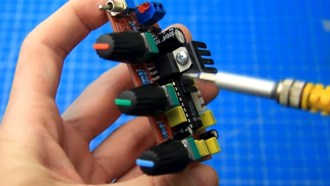
The L7812 stabilizer is linear and it decently heats up during operation. To cool it, you need to install a small radiator on this stabilizer.
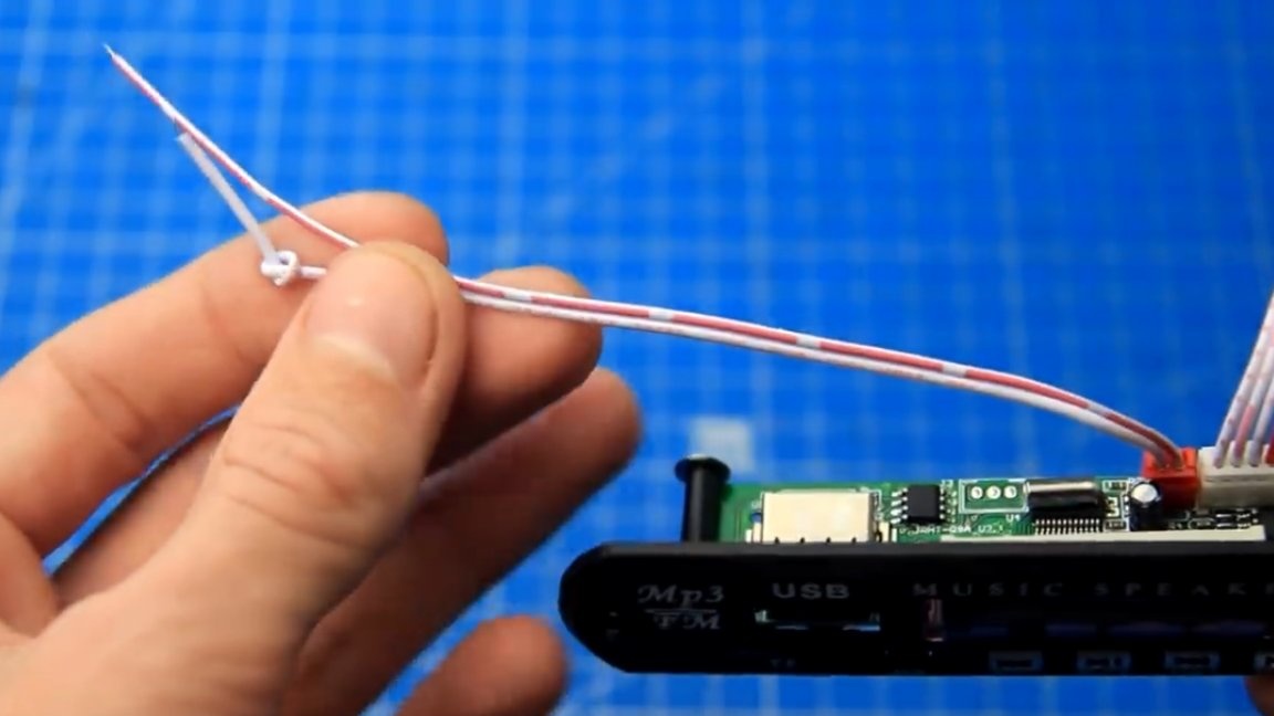
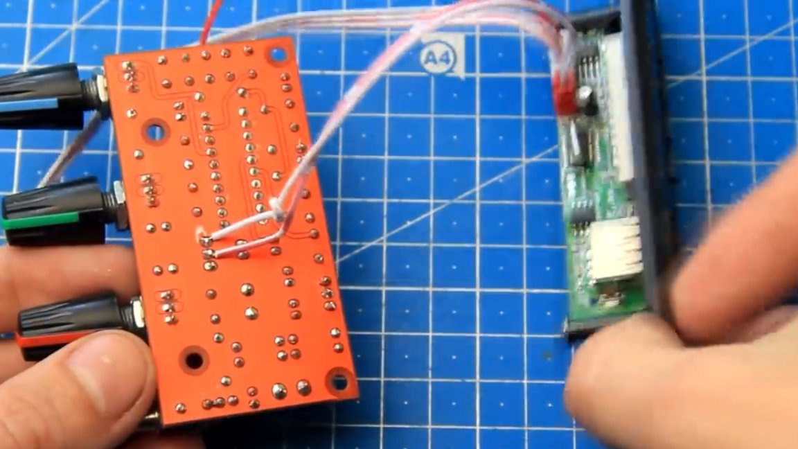
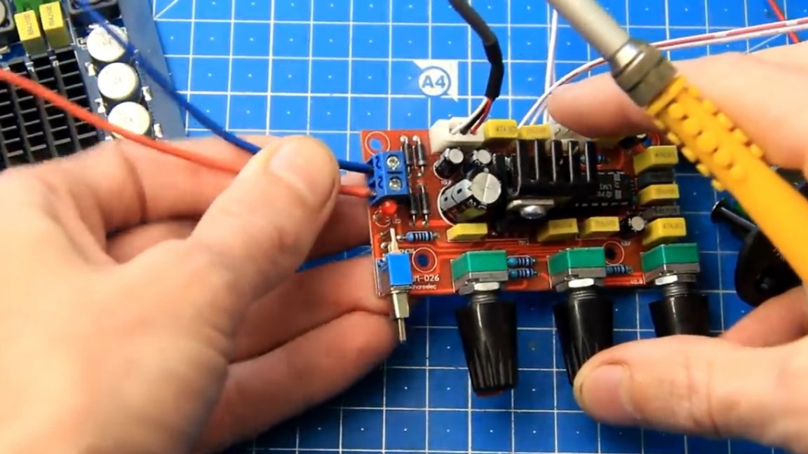
A special separate connector plus (+) and minus (-) is provided for power on the mortise module. For convenience, the author additionally indicated a plus (+), tying a knot on it.
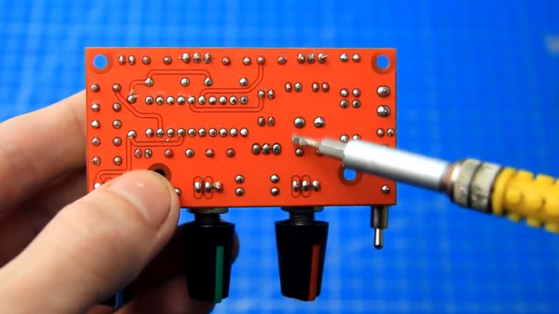
Both of these wires must be, observing the polarity, soldered to minus and the 12V output of the stabilizer L7812 on the timbral block.
Also, the audio line output from the sound module must be soldered to the input of the tone block.
On the sound module there is an antenna wire (it is red) and 3 wires of the linear output: the left channel, the common and right channel.
First, solder the power wires of the mortise module to the output of the L7812 chip on the timbral block. This is how it looks now.
The line-out wire needs to be soldered to the input of the tone block, that's right there, without crossing the wires, there’s nothing complicated either.
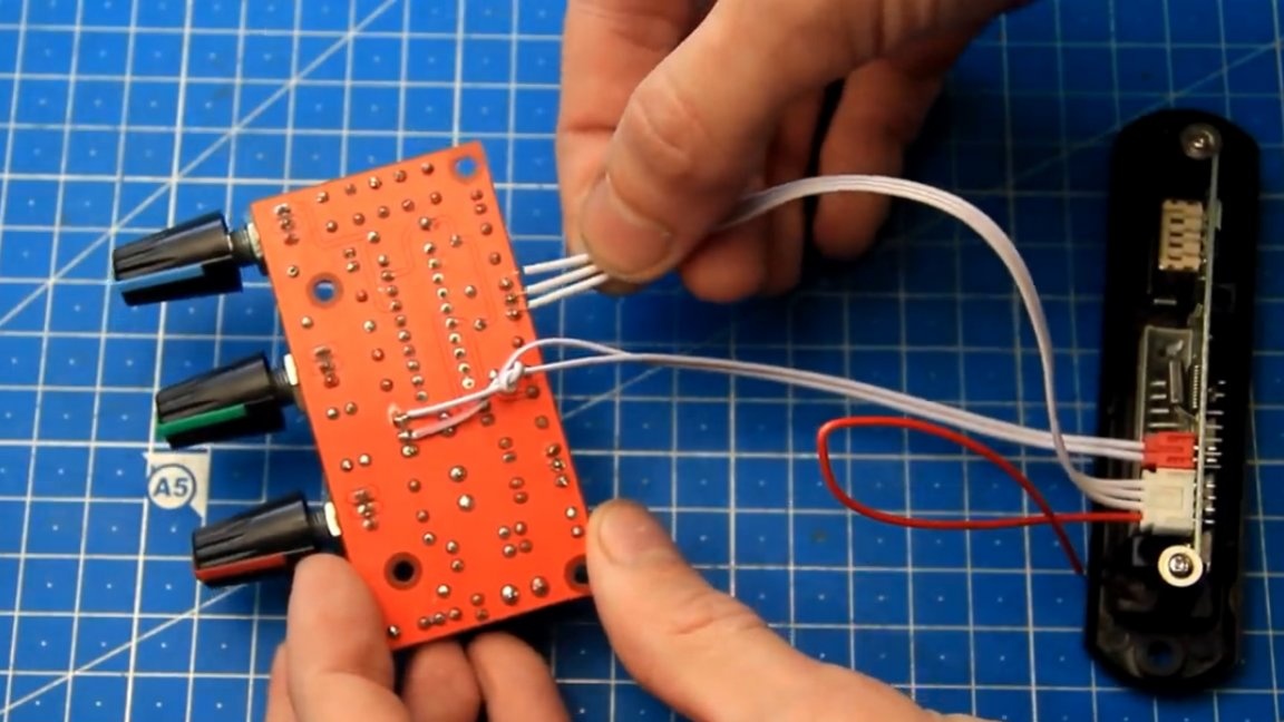
Everything, the sound module and the timbral unit connected. This, perhaps, was the most difficult stage in this assembly.
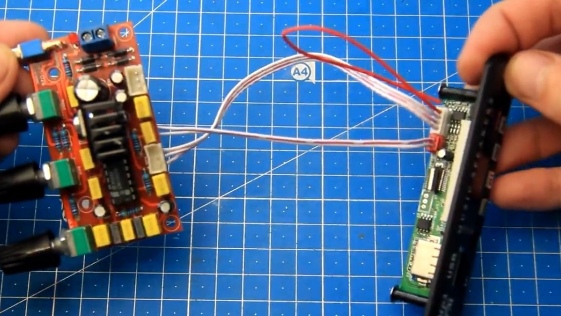
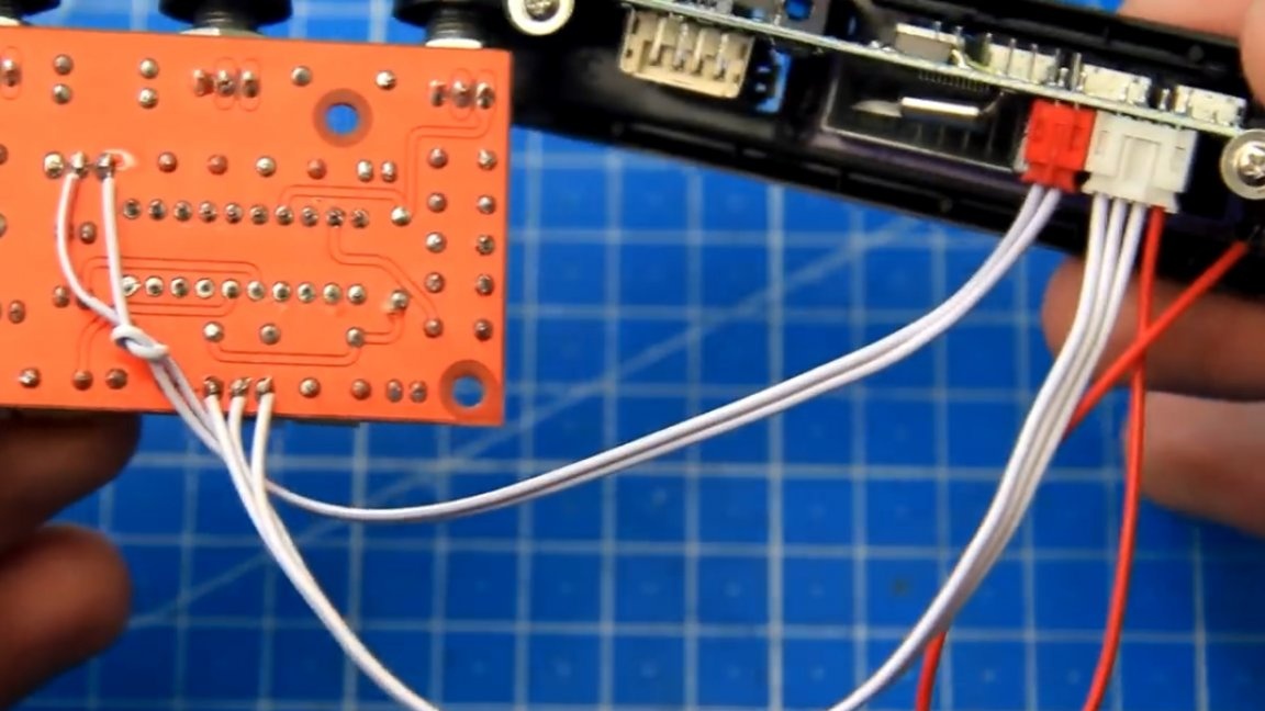
A normal shielded wire with connectors went straight from the kit to the line input of the sound amplifier board. Therefore, our task is simplified, just take this wire and connect it to the output of the tone block, the connector, as you see, is suitable.
The sound is everything. All wires are connected. First, the signal from the sound module goes to the timbre block, it is regulated / adjusted at will, and then it goes to the amplifier.
Now we need to connect the amplifier and the timbral block to the power source. Such colored wires with a cross section of 2.5 squares are perfect for this task.
First of all, we connect the power wires to the tone unit. There is a diode bridge on it, so the polarity of the connection in this case is not critical. Let the red wire be a plus, and the blue wire a minus.
That's it, we connected the power wires to the timbral block, now we’ll deal with the amplifier. Here it is already necessary to strictly observe the polarity, plus and minus are signed on the board itself.
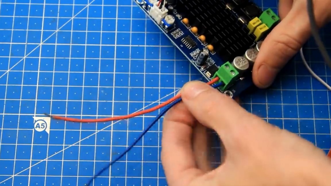
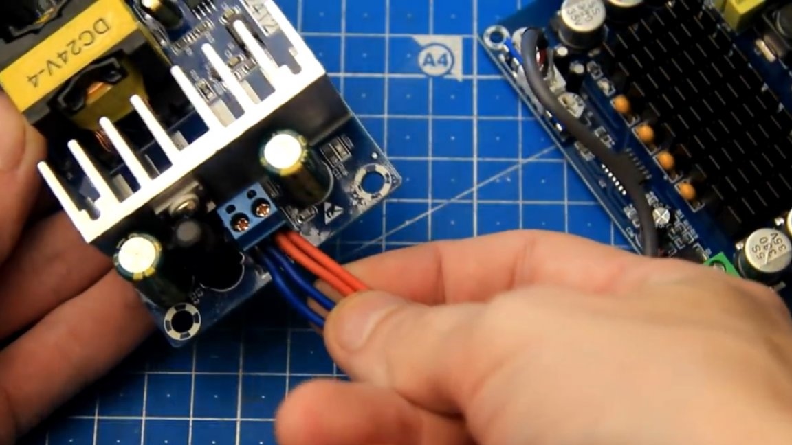
The red wire here is also a plus, and the blue wire is a minus. The next step is to connect the power supply wires of the amplifier and the tone block to the output of the power supply, while always observing the polarity. Connect the power to the amplifier and the tone block in parallel. To do this, take both red wires together and connect to the plus of the power supply.
We connect the blue wires in the same way together and connect them also to the power supply, but by minus (-).
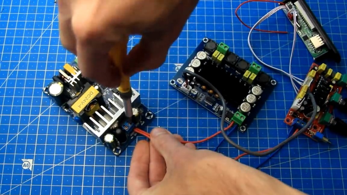
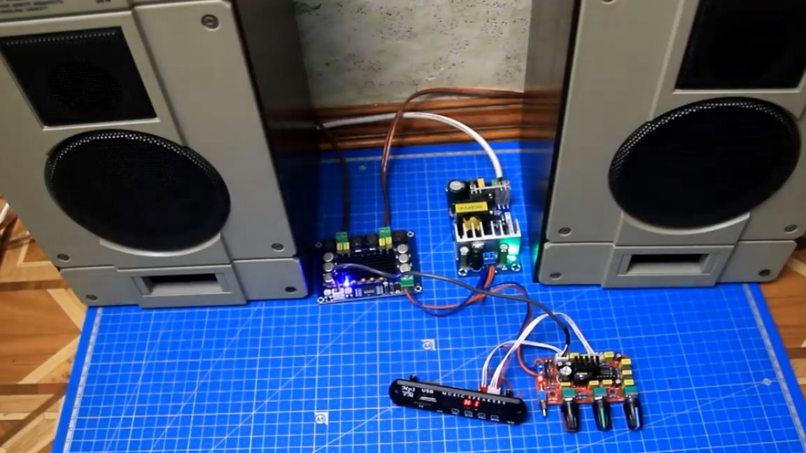
The power supply wires of the amplifier and the tone block from the power supply are connected. Well, we’ve done everything, all the modules are interconnected. As you see, there is nothing complicated here, in principle, the main thing in this matter is not to rush anywhere and check everything carefully.
Now let's feed our assembly from the 220V network. For this, the author uses such a wire with a plug.
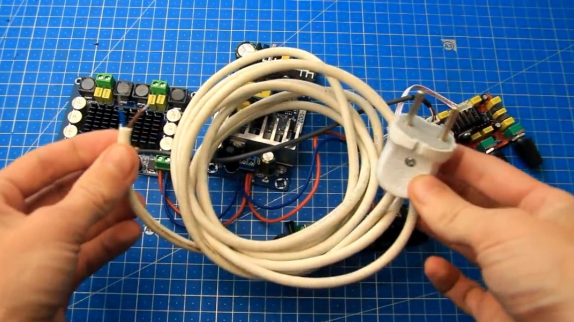
We connect one end of this wire to the 220V input of the power supply.
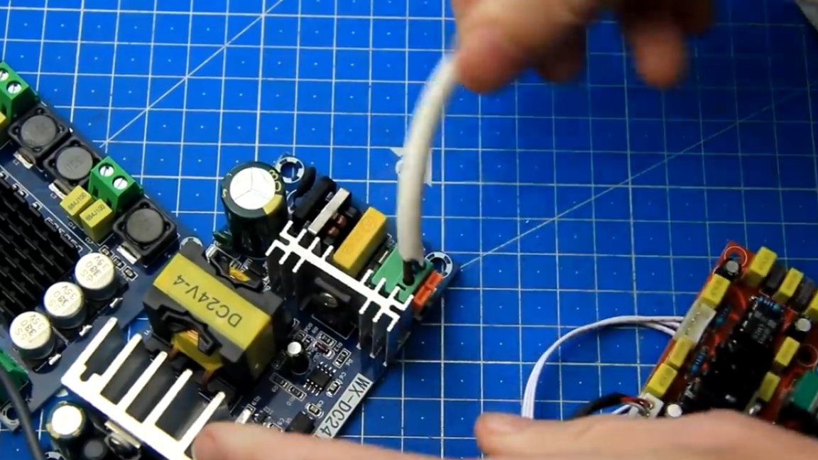
Important! A high voltage of 220V will be supplied to the power supply, this is dangerous and therefore compliance with safety regulations is mandatory!
We plug the plug into the network and, as we can see, all modules, without exception, signal to us that there is power supply with glowing LED indicators.
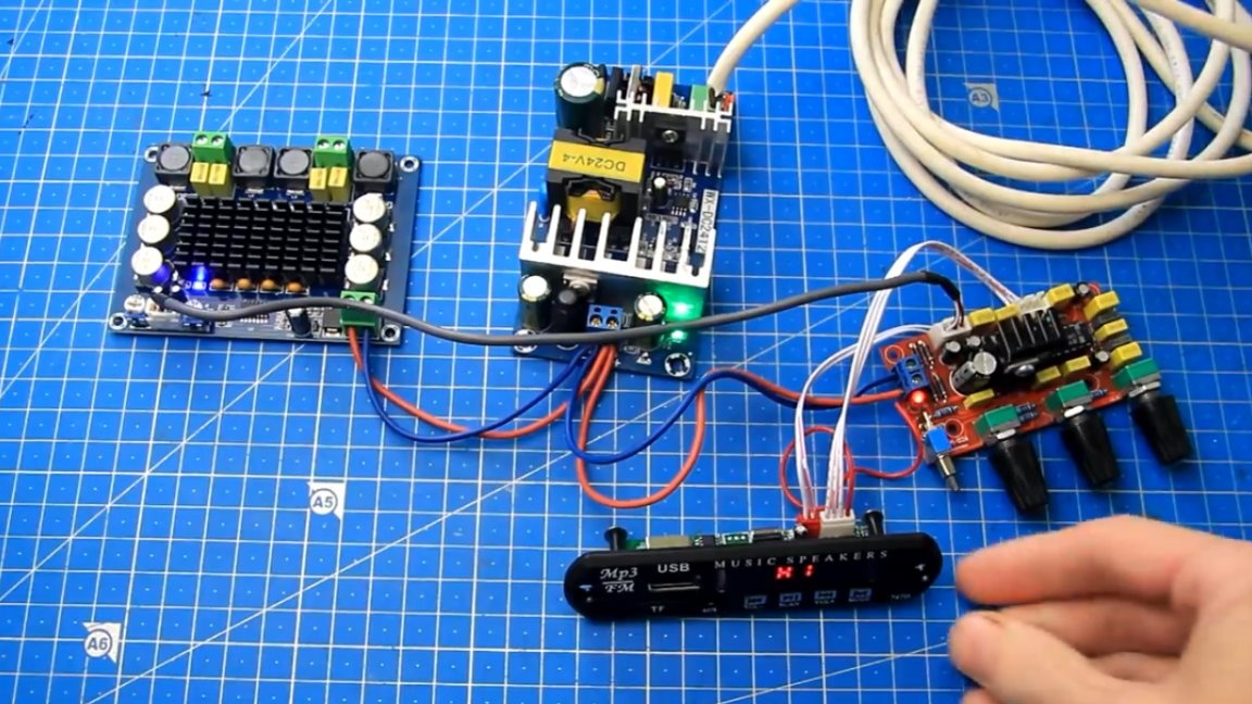
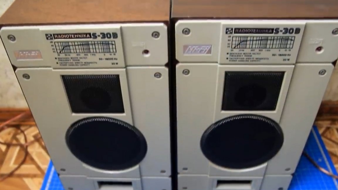
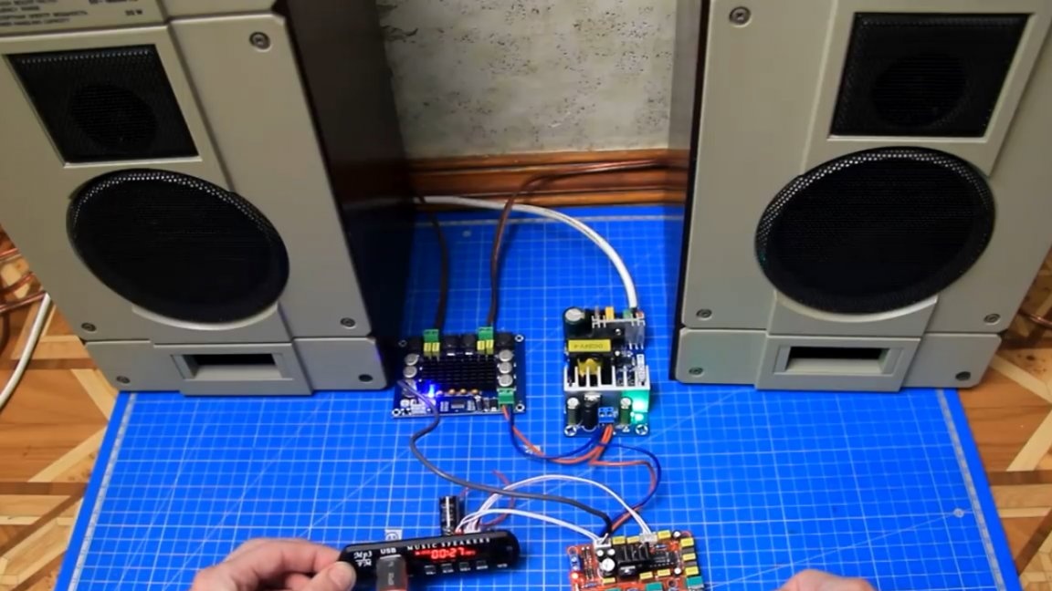
This is a good sign and at least we have no mistakes in nutrition; everything is assembled correctly. Well, in order to conduct a full performance test, you need to connect speakers to the amplifier outputs. The author uses the following: Radio engineering S-30B.
The speaker wires were connected to the amplifier outputs.
Now we try to supply power to the assembly with speakers already connected.
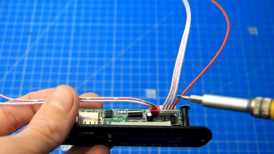
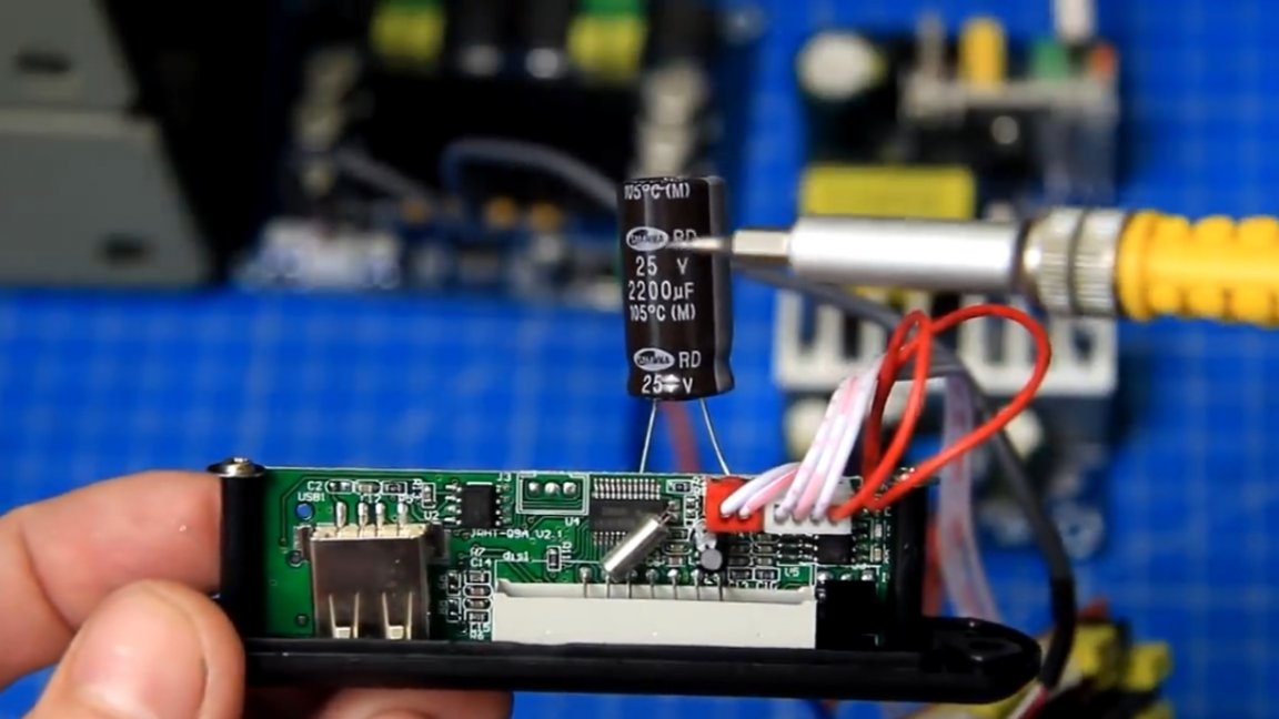
When turned on, not loud, but still cotton is heard. Everything is fine, there is music in the columns, which means a working scheme. But at the same time, an extraneous background from the processor of the mortise module is quite clearly audible, which interferes with low volume and it would be advisable to get rid of it. To do this, it is enough to install an additional electrolytic capacitor with a capacity of 2200 μF on the power supply on the sound module.

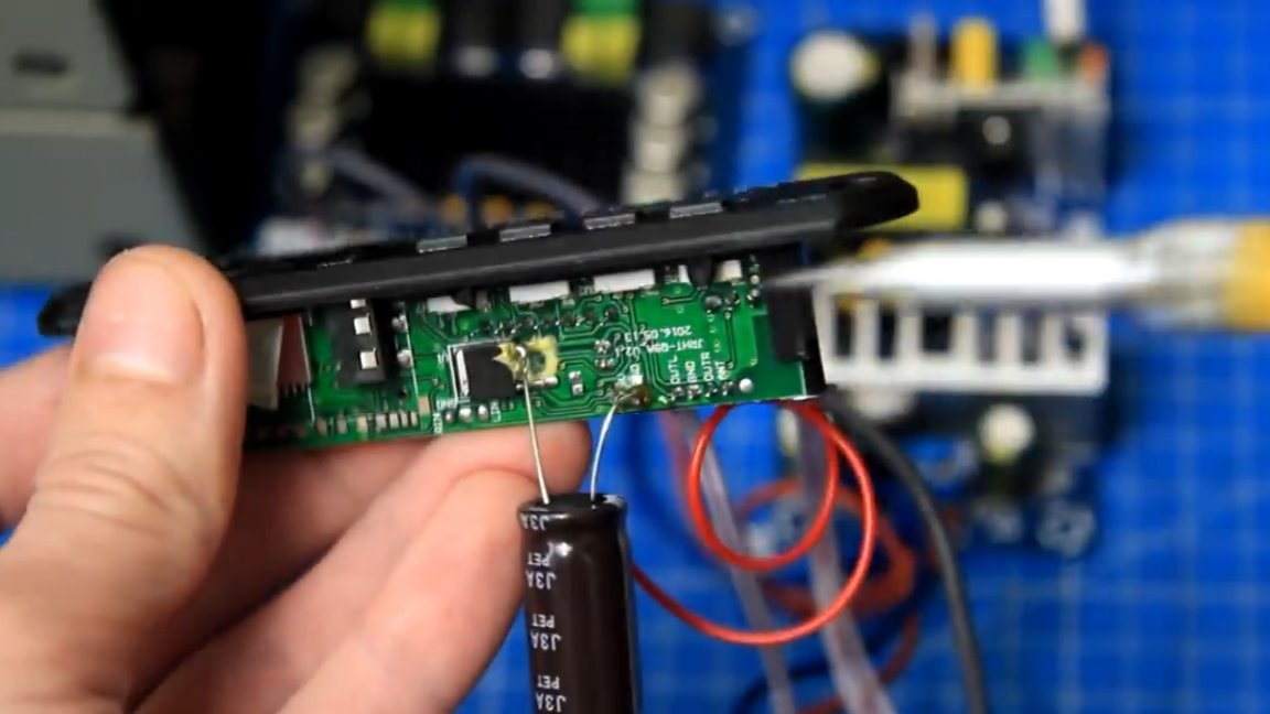
Solder the minus leg of the capacitor to minus the power supply of the module, and the plus to the output of the chip 78M05.
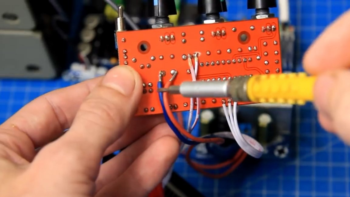
Also on the timbral block, the author removed the power wires from the terminal block and, observing the polarity, soldered them after the diode bridge to the filtering power capacitor of the timbral block, as if bypassing the diode bridge.
And after completion, we again supply power to the entire structure.
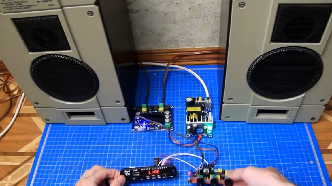
Well, there is no extraneous noise.This, you see, is excellent! The radio works, stereo, but for a more confident reception you need a larger antenna. Nevertheless, everything works, everything is fine.
Now connect the USB flash drive with test music. There is loudness in the timbrolock and this is a plus. We try to turn the knobs on the timbral block. There are adjustments and are working fine.
Everything plays perfectly, the amplifier assembly turned out. You will learn more about the assembly process, as well as test tests, by looking author video:
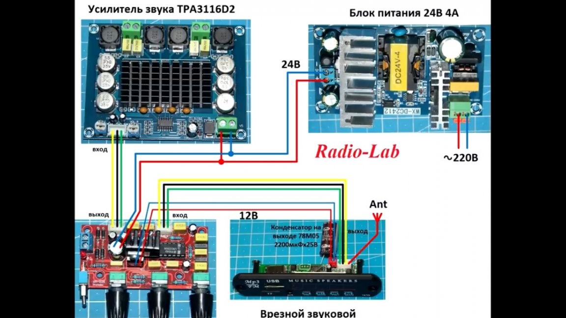
By the way, this is how the final module connection diagram:
For this assembly, the author tried to choose budget components, because the task was to assemble a normal budget amplifier, and so that anyone could repeat it. The amplifier, by the way, plays loudly and easily downloads these test speakers, in the apartment, according to the author, all this sounds quite loud, without distortion. The output power is approximately 35 W per channel with a load of 4 Ohms, which is more than enough for most home use.
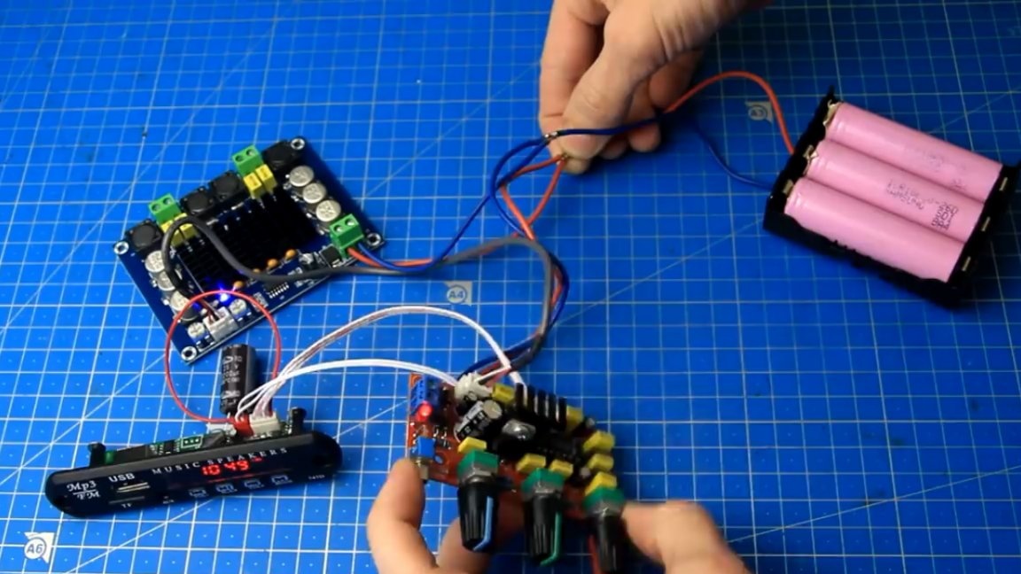
It remains to install all this in the case, add the connectors, and here you have a budget, but normal high-grade ready-made sound amplifier for a house or a small room. For beginners, in order not to work with a high voltage of 220V, instead of a 220V power supply, for example, a lithium-ion battery with a voltage of 12V can be used. Everything also works fine, except that the output power of the amplifier will be slightly lower. By the way, here's an idea for assembling a portable speaker. Try, collect and repeat.
Thank you for attention. See you soon!