

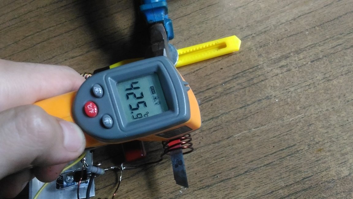
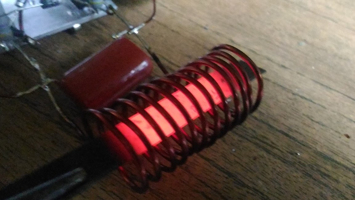
Hi in this homemade I will show the process of creating a powerful but simple induction heater. This "inductor" is capable of heating the steel blade "to red" in a matter of seconds. With it, you can "heat" objects (tools, nails, screws), as well as melt various materials (tin, aluminum, etc.).
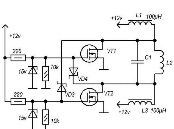
Here is the circuit to be assembled
Before you start reading the article, I recommend that you look at the assembly and testing process:
[media = https: //www.youtube.com/watch? v = cEaiQcxifcM]
We will need:
- 2 transistors of the brand IRF3205
- 2 zener diode 1.5ke12
- 2 diodes HER208
- 2 resistors at 10k and 220Ω
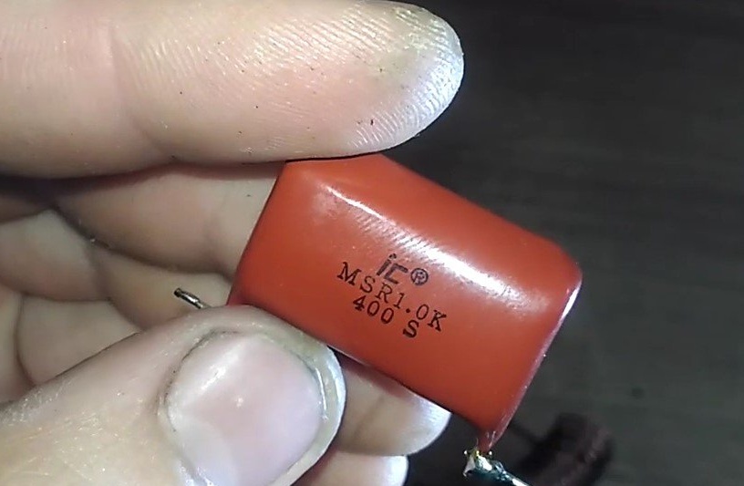
- Film capacitor at 400V 1mkF
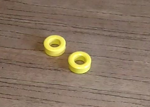
- 2 ferrite rings (can be obtained from the old computer power supply)
- 2 insulating washers
- Radiator (for cooling transistors)
- A pair of screws (for fixing transistors in a radiator)
- Thermal grease
- 2 pieces of mica (for isolation of transistors from a radiator)
- Copper varnished wire with a section of 1.4 mm2 1 meter long
- The copper varnished wire with a section of 1.2 mm2 2 pieces of 1.5 meters
- Form on coil winding (I will use a 18650 battery)
- Battery for powering the circuit (8-20V)
- 2 small pieces of wire
And:
- Side cutters, knife, screwdriver, soldering iron.
Detailed manufacturing description:
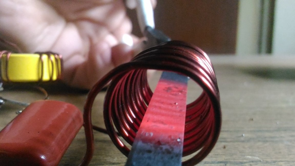
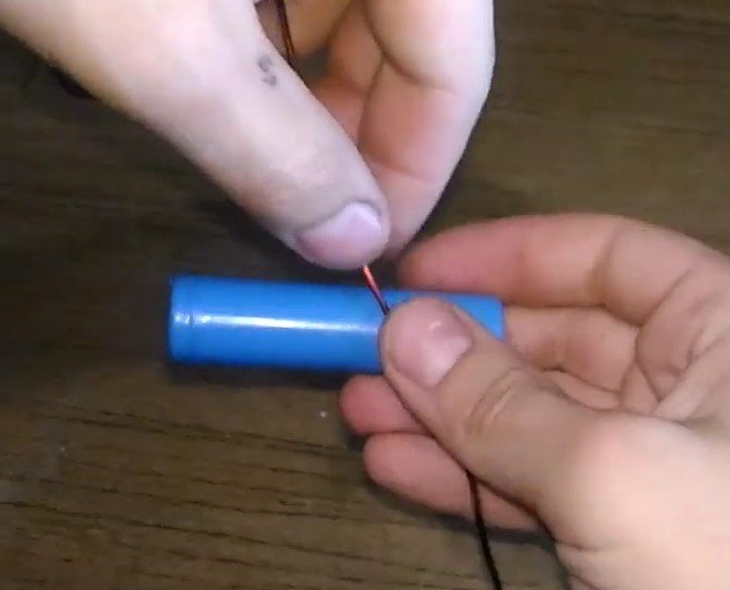
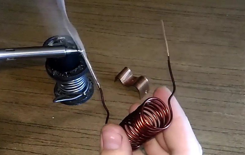
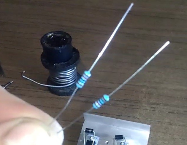
Step 1: Winding the coil. The first step is to wind the 1.4mm wire2 on the "form" (once again I remind you that I will use a 18650 battery as the "form") to get a coil.
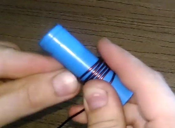
It should be something like this
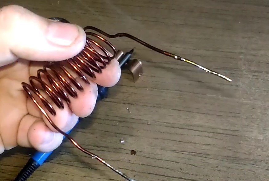
Next, with a knife, remove the insulation from the coil
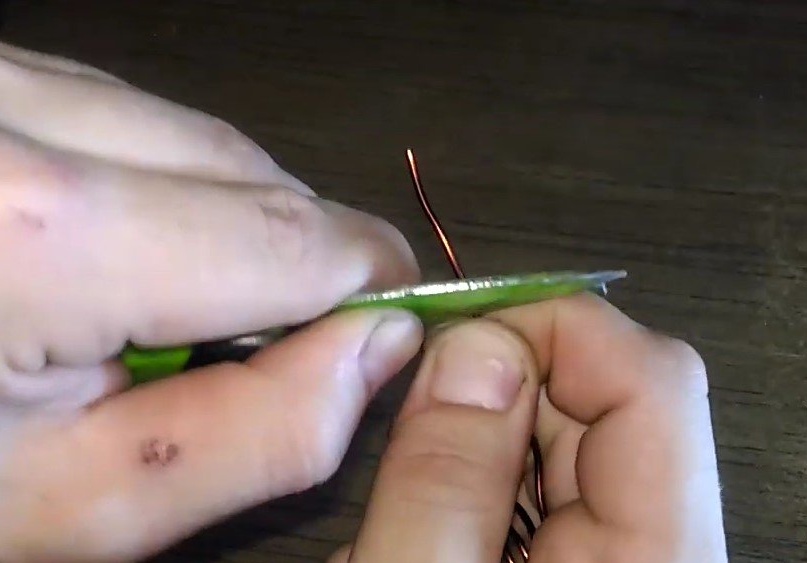
And tin wires
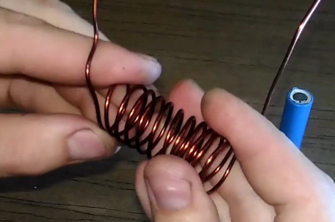
It should be something like this
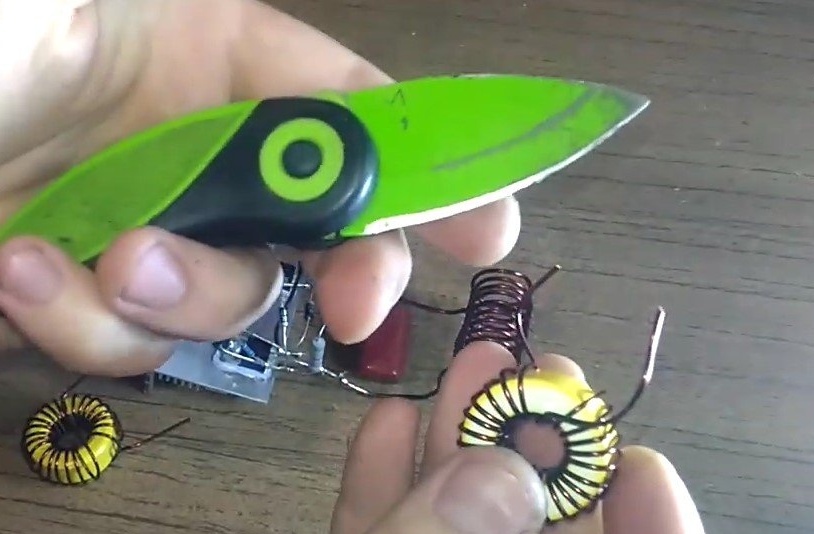
Step 2: Winding the coil on ferrite rings. At this stage, it is necessary to wind the 1.2mm2 on ferrite rings.
To do this, take the ring and extend the wire into it.
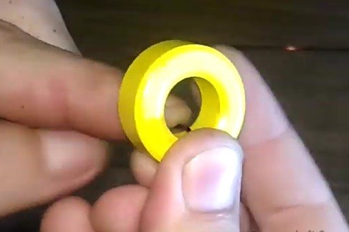
And start winding
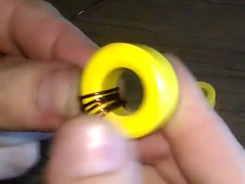
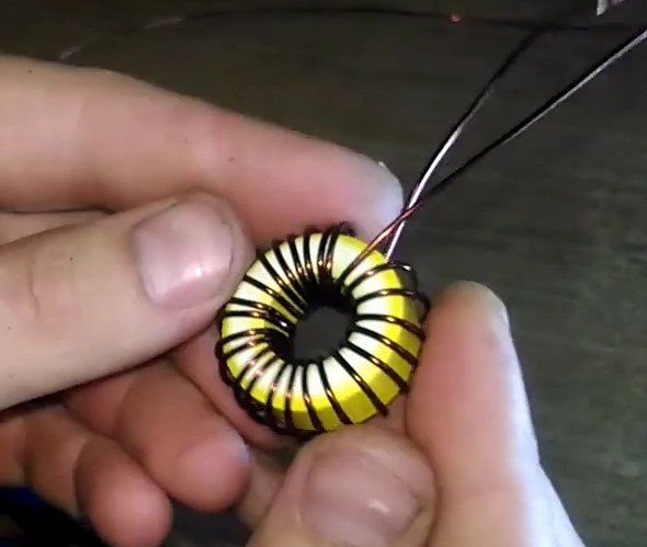
Please note that the turns should be tight. As a result, we get this.
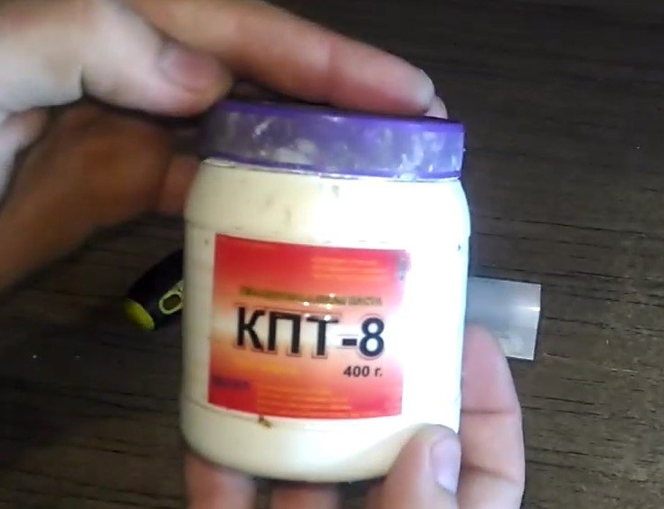
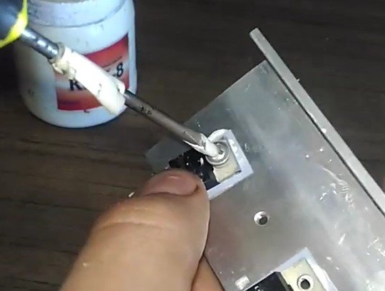
Step 3: Securing and preparing transistors. First, prepare the thermal grease. I will use the very common KPT-8.
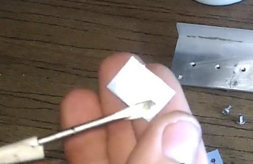
It is necessary to apply a thin layer of thermal grease over the entire area to 2 pieces of mica.
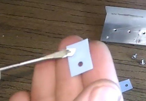
What would happen like that.
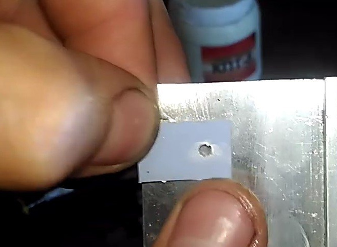
Then we glue the mica onto the radiator
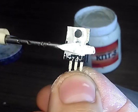
We do the same with the transistor itself.
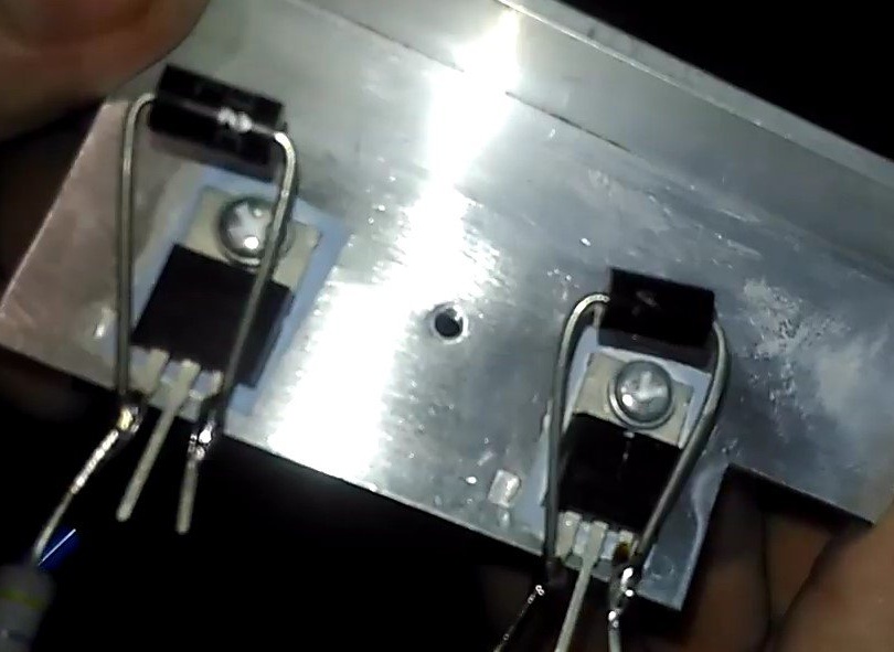
Carefully lean the transistor (between the mica) to the radiator.
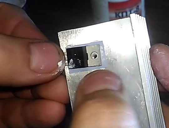
And fasten it with a few screws.
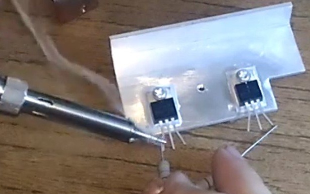
We do the same with the second transistor.Thus, at this stage, there are already 2 transistors bolted to the radiator and ready for further soldering.
Step 4: Soldering components according to the scheme.
At this stage, the most interesting part begins. After its completion, a completely finished device will already turn out.
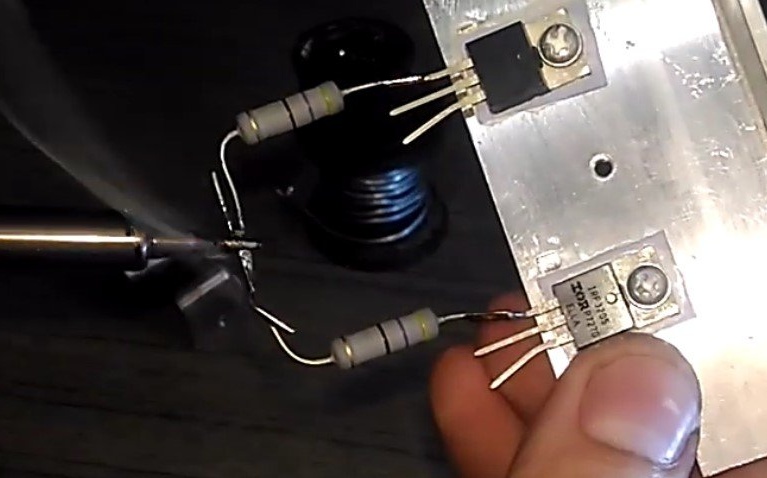
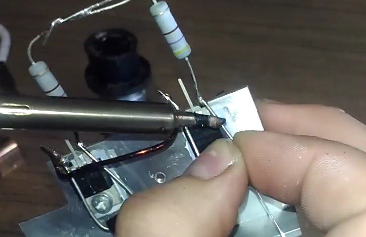
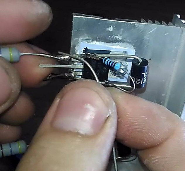
We will prepare 2 resistors for 220 ohms.
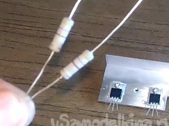
They need to be soldered to the left legs of the transistors.
And then connect the remaining ends to each other and tin.
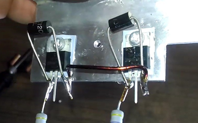
Then you need to prepare the zener diodes.
They must be soldered between the left and right "legs" of the transistor. All this is done with 2 transistors.
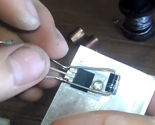
What would happen like that.
Now you need to connect the "right" legs of the transistors (sources) with a jumper. In its role, the remainder of the varnished copper wire will serve.
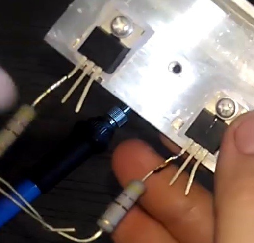
Prepare 2 resistors per 10 kOhm
Then we connect the left leg of the transistor (gate) with the right leg (source) of a 10 kΩ resistor
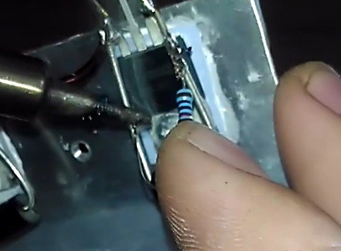
We do the same with the second transistor. We get a semblance of this.
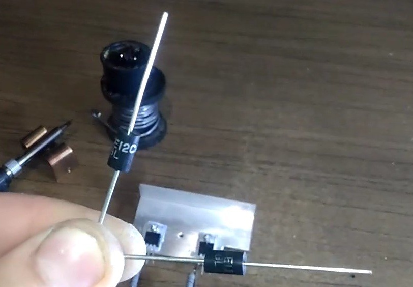
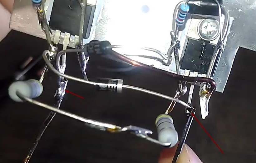
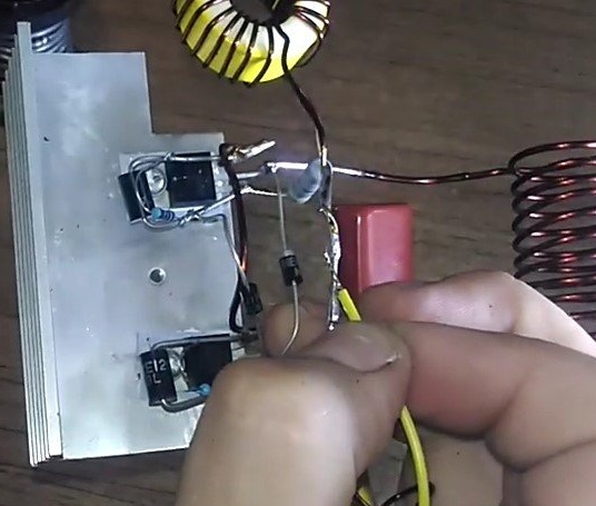
Now it is the turn of the diodes.
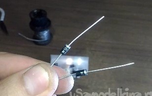
It is necessary to solder the anode of the diode (triangle icon) to the left leg of the transistor.
And the second end of the diode to the central leg to another transistor.
After doing the same, but with a different transistor.
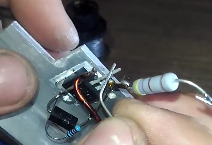
Next, you need a coil, which was made in the first stage
Its ends must be soldered to the drains of transistors (central legs of transistors).
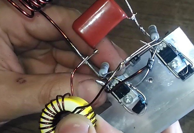
Next you need to solder the capacitor between the coil as in the photo.
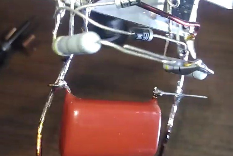
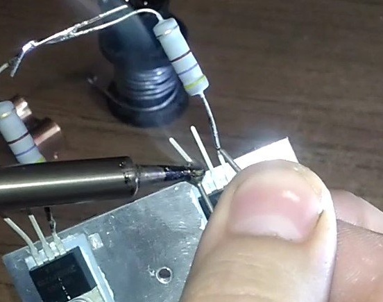
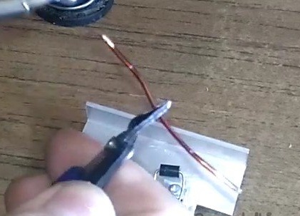
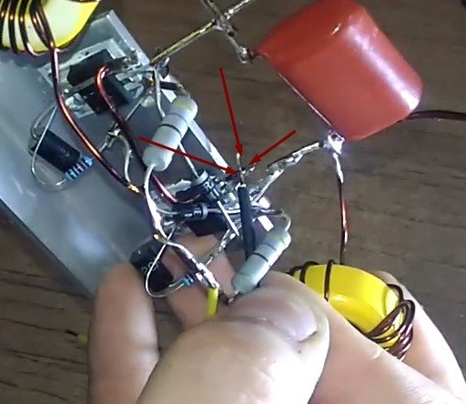
One of the last stages and the connection of chokes. But first you need to prepare it, for this you remove the insulation and tin the ends.
Following this, on each side of the transistor it needs to be soldered to a common connection point with a 220 Ohm resistor and the place where the capacitor is soldered.
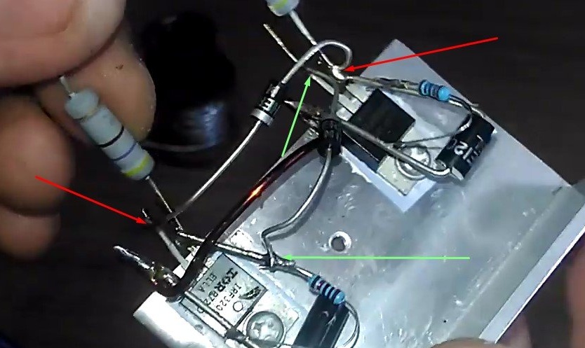
Now you can prepare 2 small pieces of wire (desired different colors) to power the entire circuit. One of the wires (yellow in my case) is soldered to the connection point of the resistors at 220 Ohms, plus will be connected here
and the black wire (minus) goes to the right foot (source) of one of the transistors.
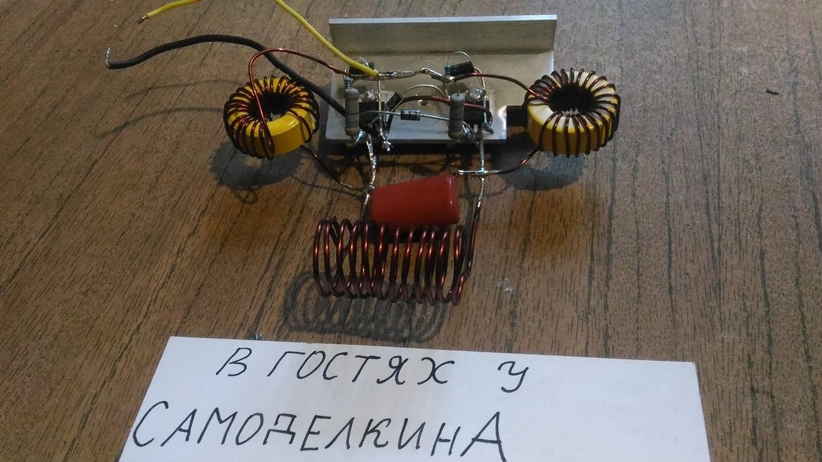
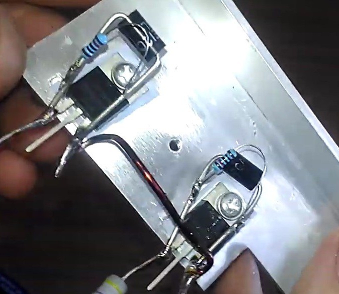
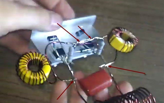
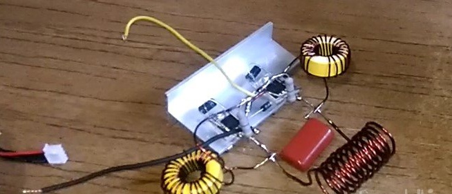
Here is the final photo of an already fully working and assembled scheme.
Step 5: Connect and Verify.
To power the circuit, I will use a Li Po battery for quadrocopters.
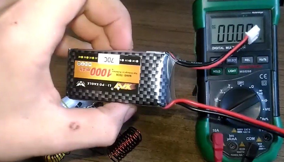
But you can use any other (or even several) voltage from 8 V to 20 V.
Plus, we solder from the battery to the wire, which is connected with 220 Ohm resistors, in my case it is yellow. But I connect through an ammeter, which would also show the current consumed by the circuit. Of course you can not do this. The minus goes to another wire (black), I recommend soldering it through the button, but for demonstration I’ll just connect them when I need the circuit to work.
My current reached 15A. These values may fluctuate depending on different conditions, just keep this in mind.
Thanks for attention. Good luck in your endeavors!