

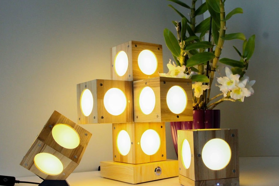
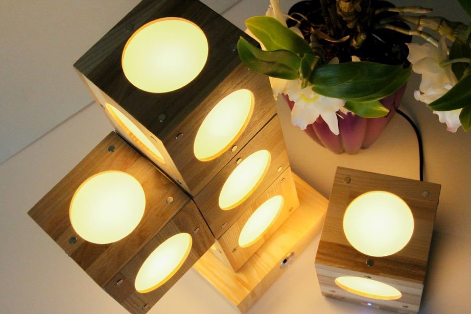
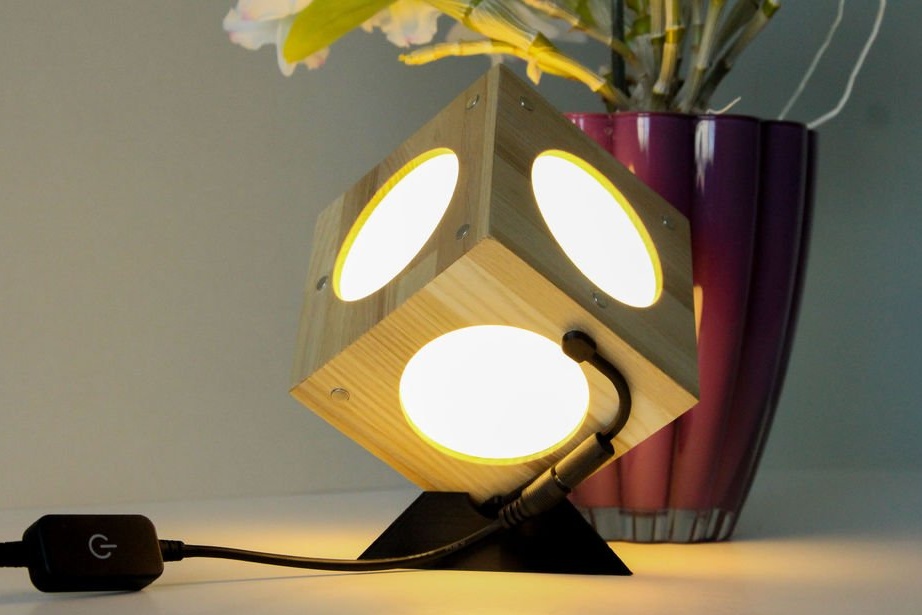
Interesting homemade made by college students. Of course, they are not the first to implement this project, but in their homemade work there are several copyright ideas. As you probably already understood by looking at the photos, this is a lamp that consists of many blocks. LEDs are installed inside the units. Three magnets are installed on each side of the cube. Magnets perform a conductive (i.e., through them goes power to the next cube) function and hold the blocks together.
Tools and materials:
- Ash board 4000x1500x15 mm;
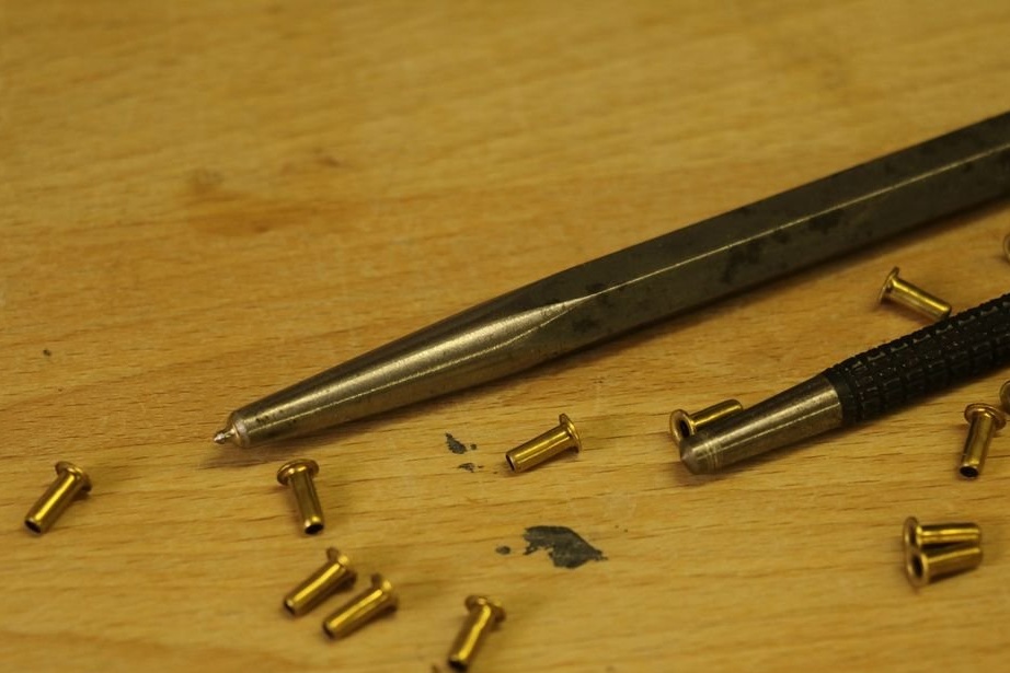
-96 rivets M3x8 mm
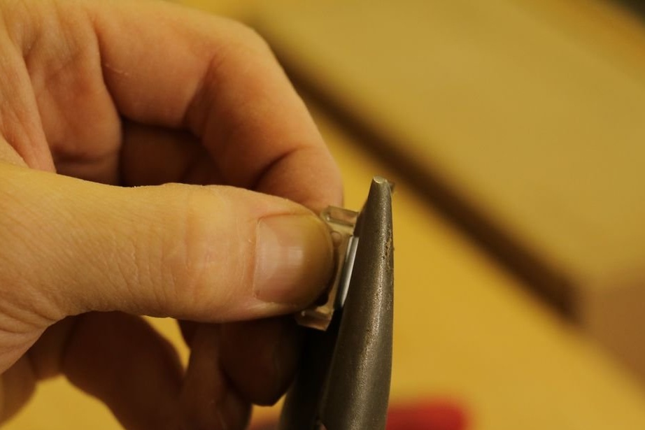
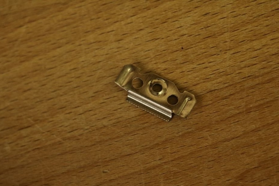
-120 metal locks for fixing glass;
-Acrylic glass frosted 480x400x2 mm;
-95 magnets 6x3 mm;
-3 magnets 6x5 mm;
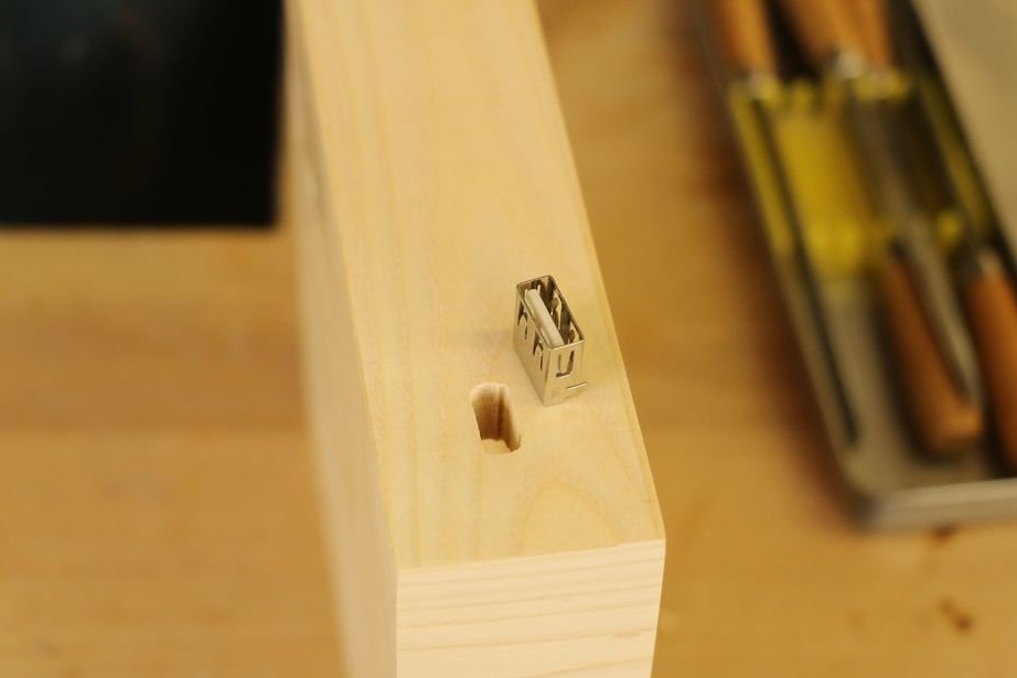
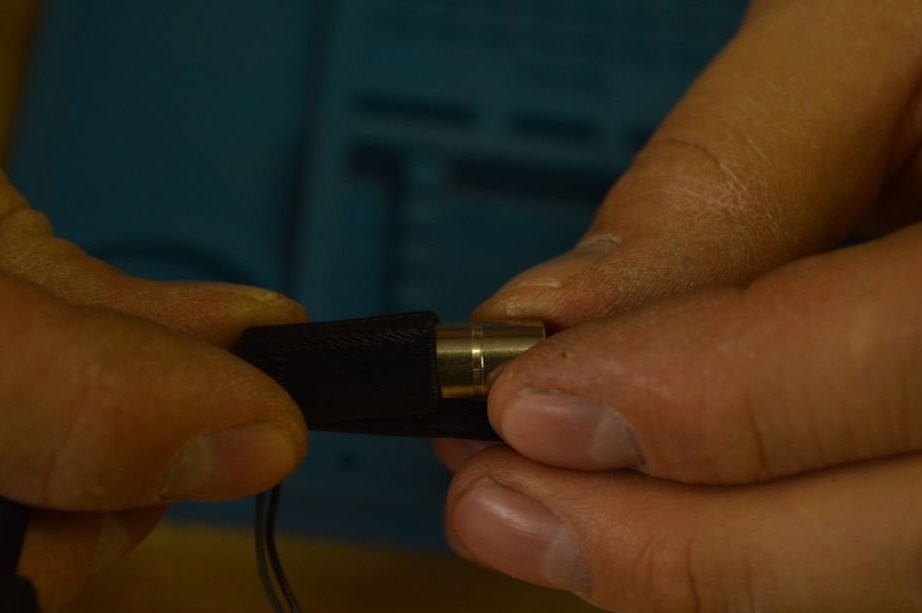
-3 connectors 5.5x2.1 mm;
- Touch switch (for a large base);
- Touch switch (for a small base);
- Touch switch (for 3D-printed connector);
-MOSFET;
-Voltage regulator;
- Lowering converter;
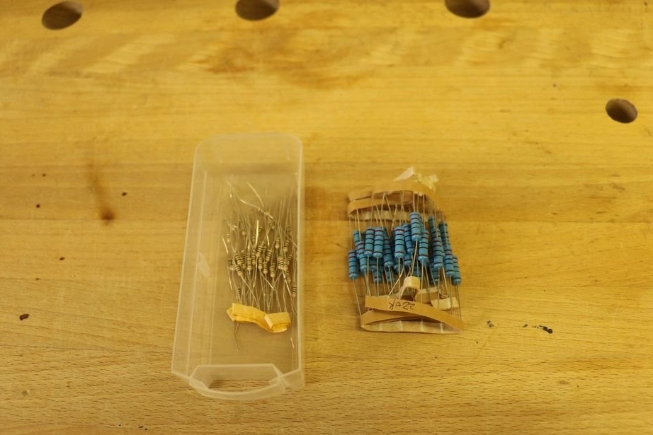
-5 2.2 ohm resistors;
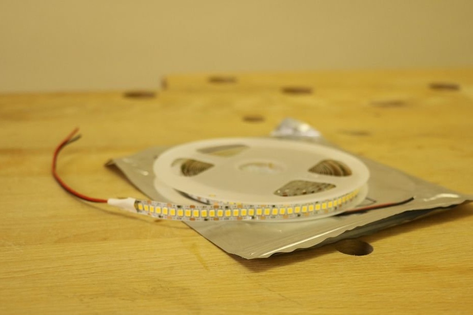
-1.5 m LED strip;
- Power supply 8A (for a large base);
- Power supply 1A (for a small base);
-11 rubber feet (diameter 8 mm);
-3mm plastic tube;
-Drill;
-Band-saw;
-Electric screwdriver;
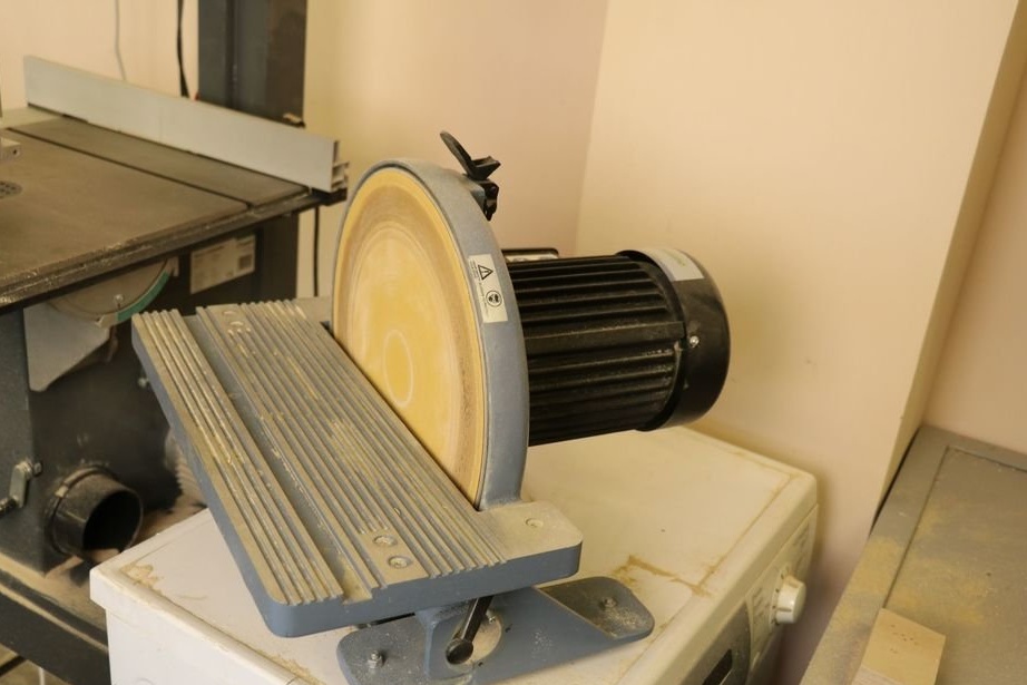
-Sander;
-Sandpaper;
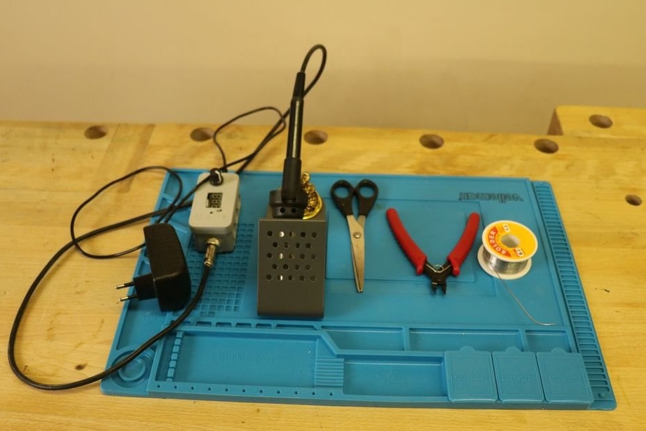
-Soldering iron;
-12V power supply;
-Multimeter;
-PVA glue;
Epoxy resin;
-Glue gun;
Riveting tool;
-Hammer;
-Calipers;
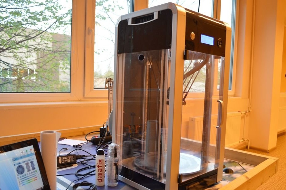
-3D printer;
-Putty;
-Varnish;
-Wire;
-Antistatic spray;
- Painting tape;
-Double-sided tape;
-Templates (files for making templates are attached below);
Part1_3magneti.DXF
Part2_3magneti.DXF
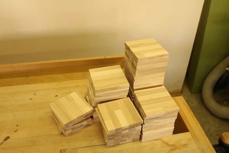
Step One: Material Preparation
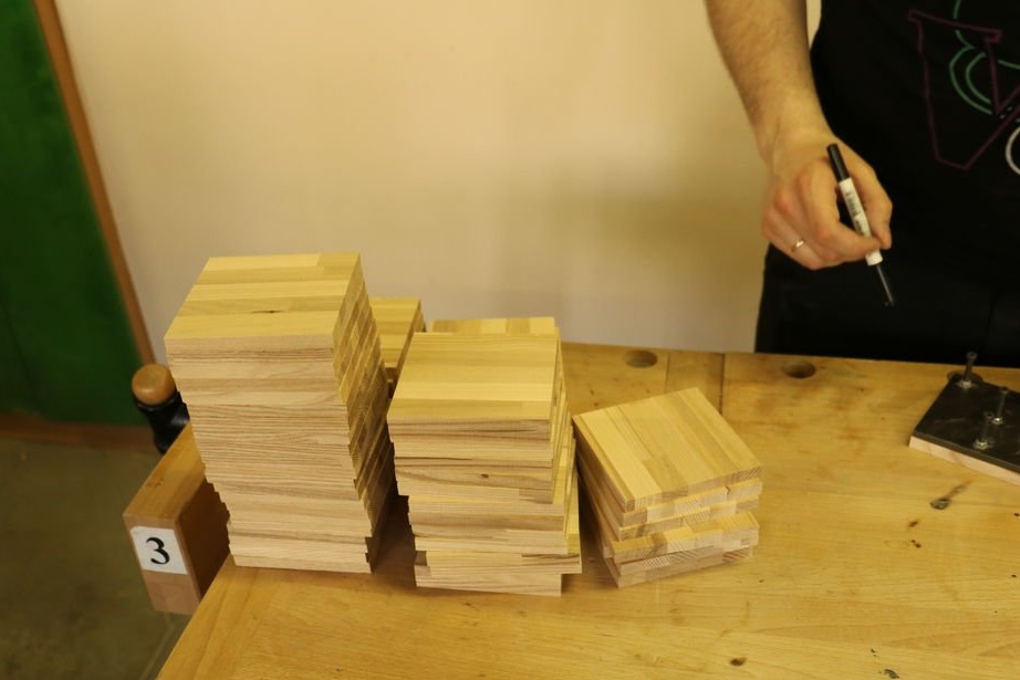
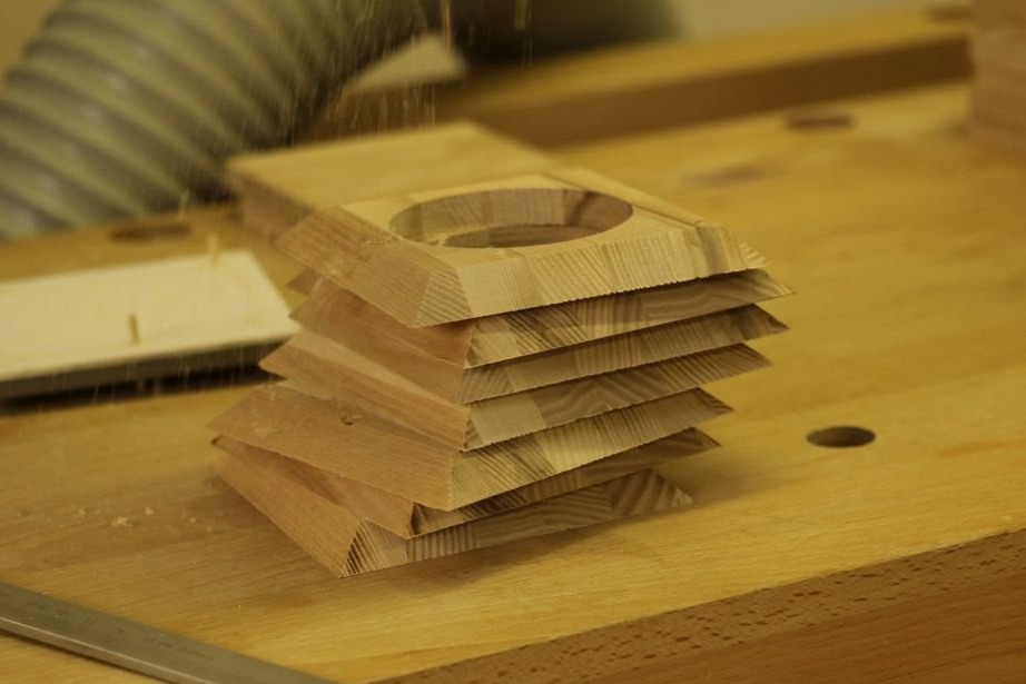
This lesson will show how to make only one block, but usually the wizard does 5 - 8.
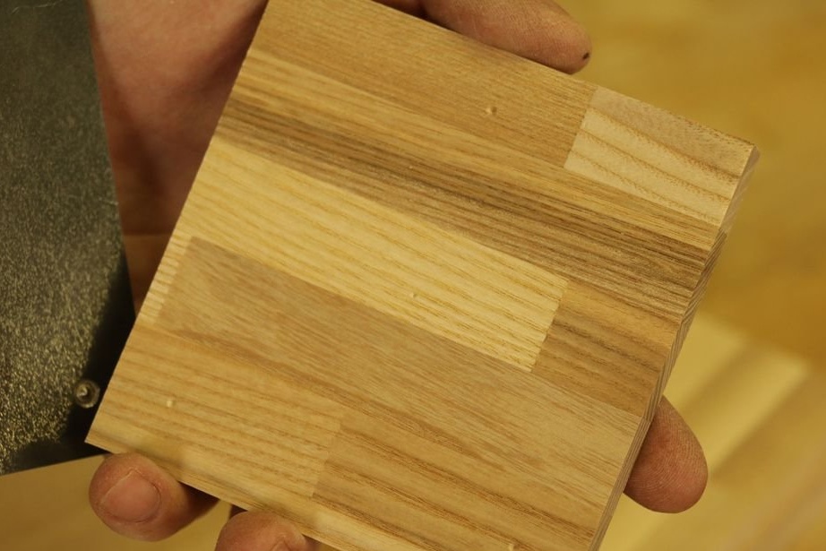
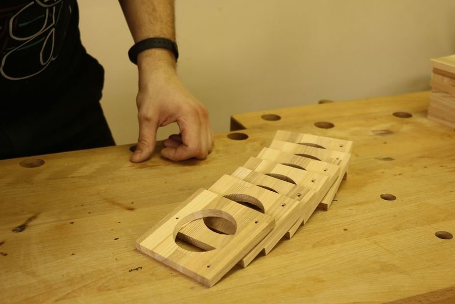
First you need to make blanks measuring 101x101x10 mm (6 for each cube) from ash or oak.
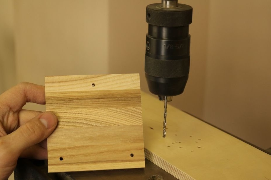
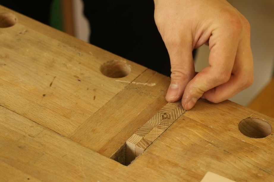
Step two: blanks
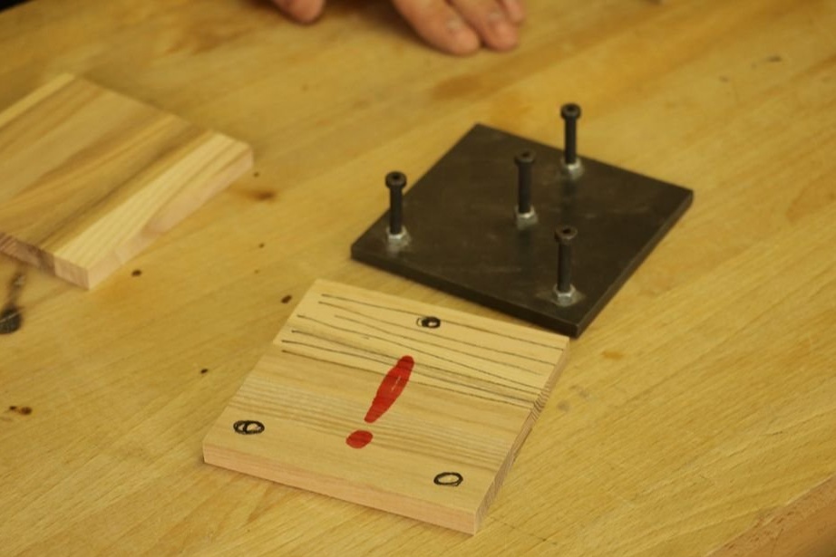
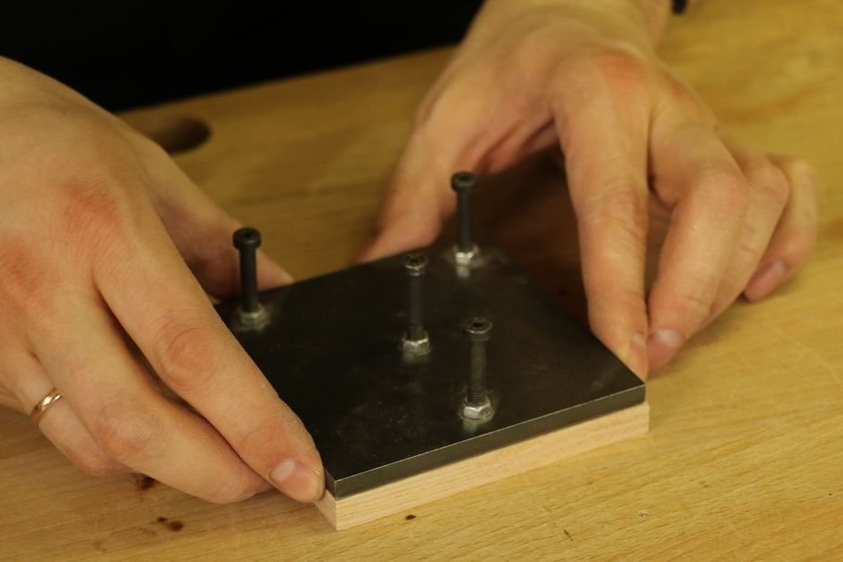
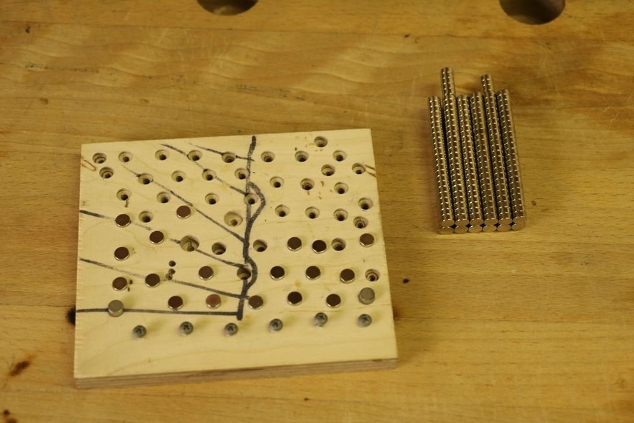
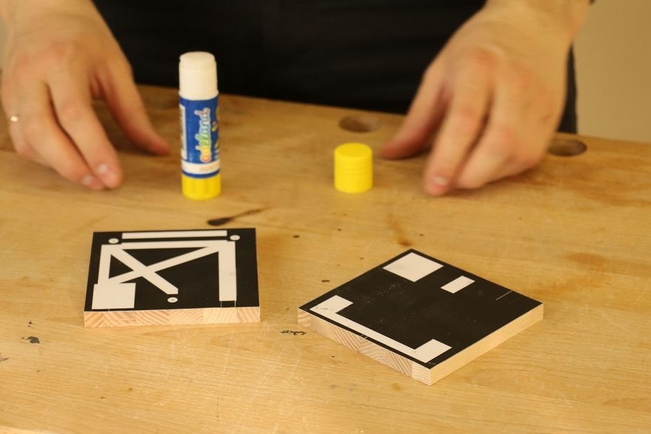
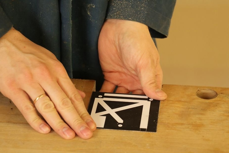
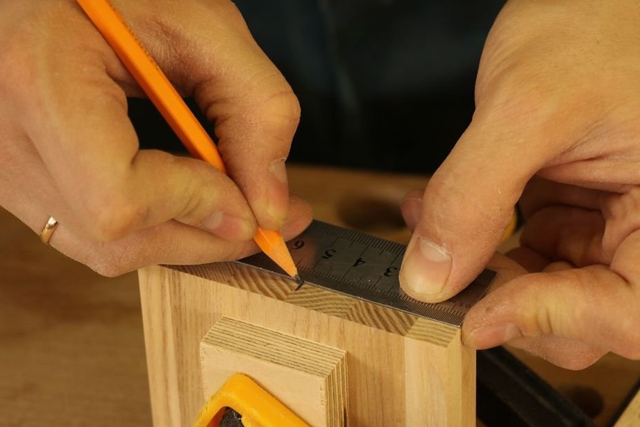
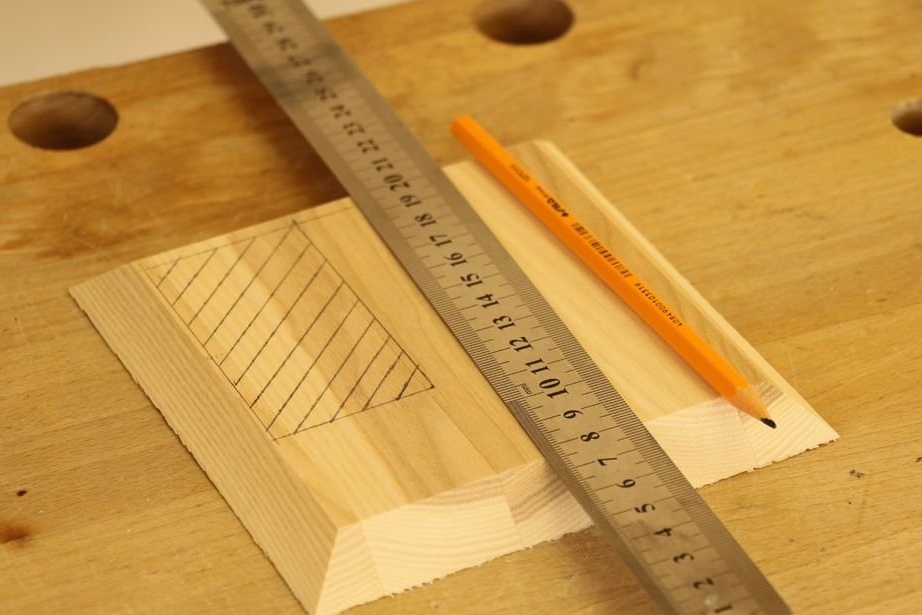
The masters made 3 templates from 6 mm steel, but you can also make them from wooden blanks (only two templates are attached).
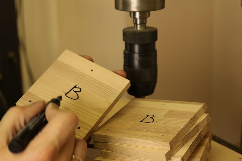
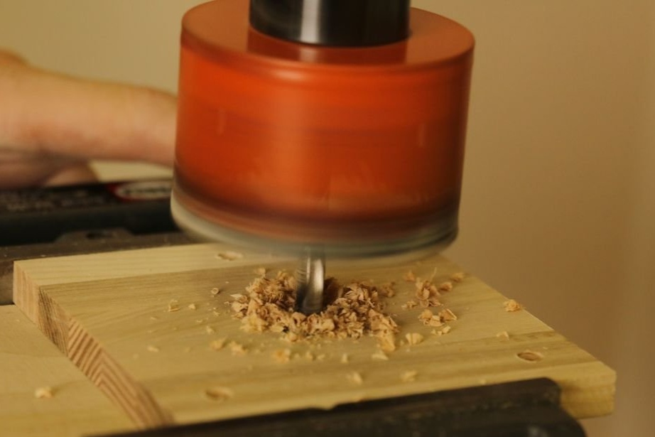
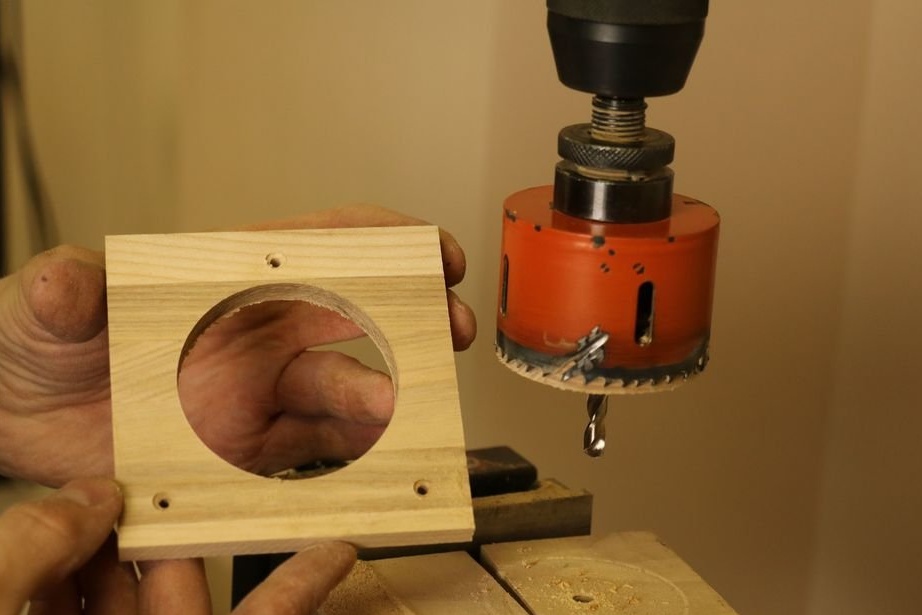
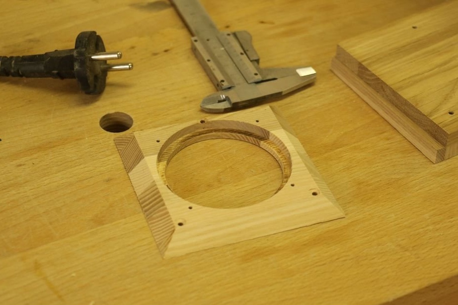
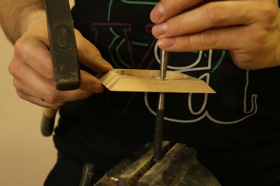
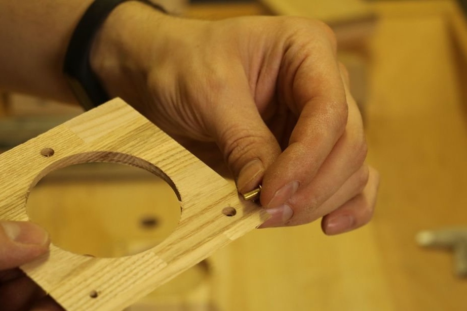
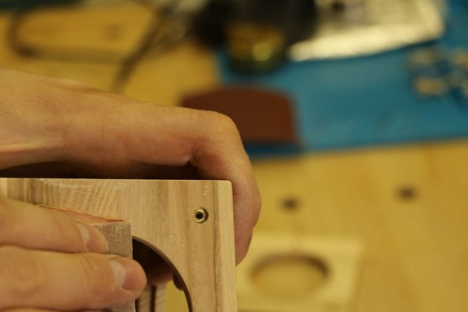
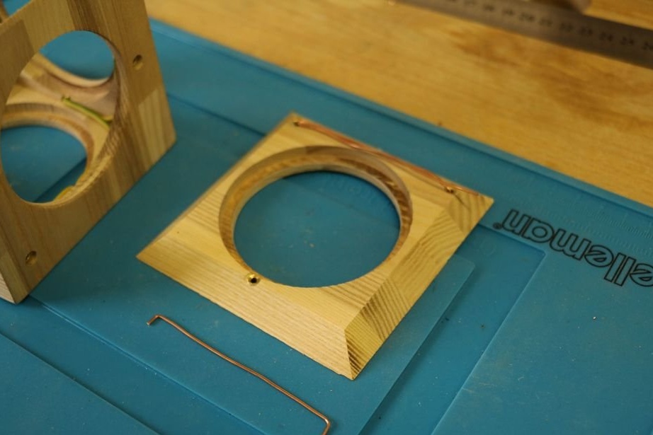
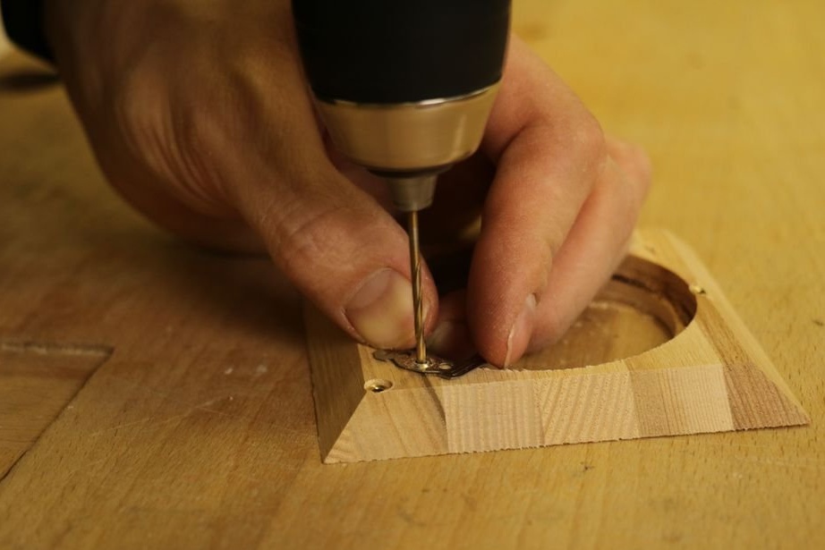
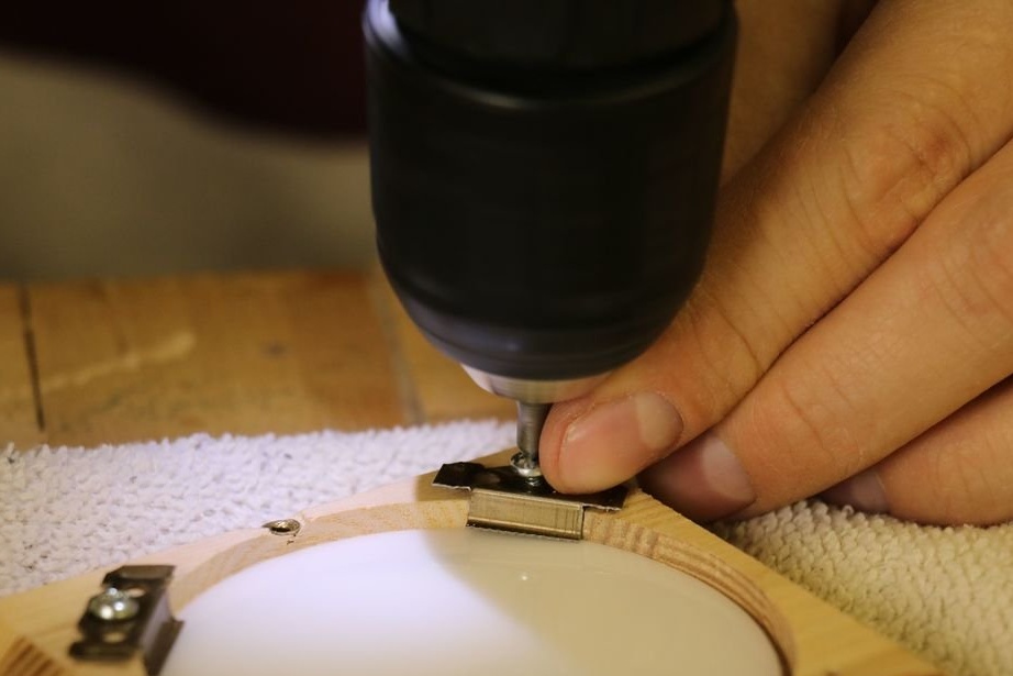
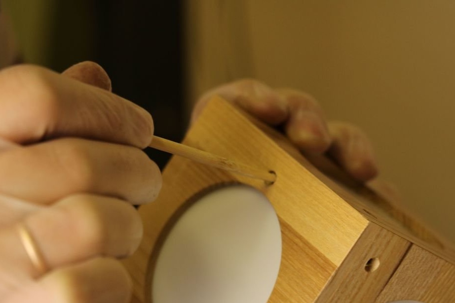
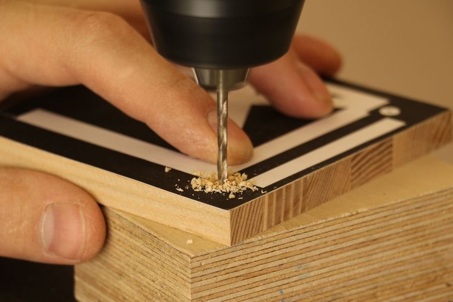
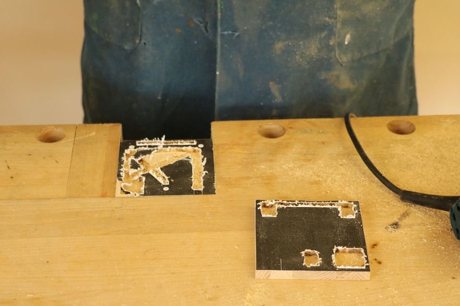
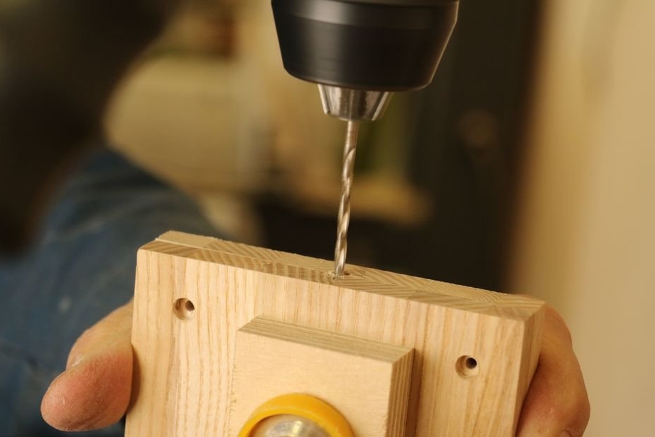
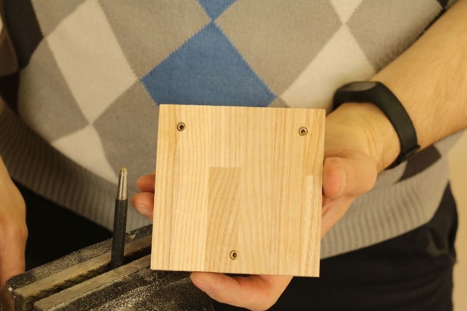
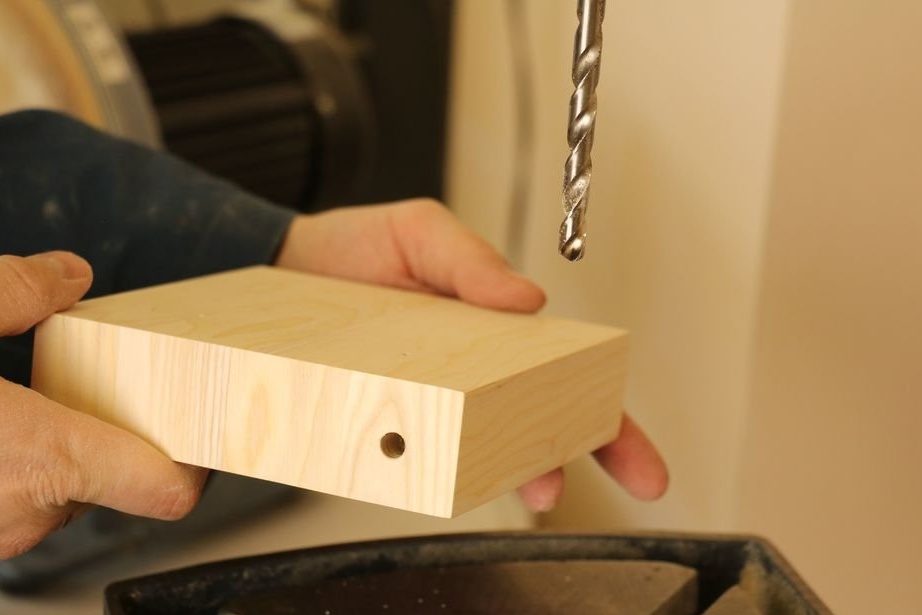
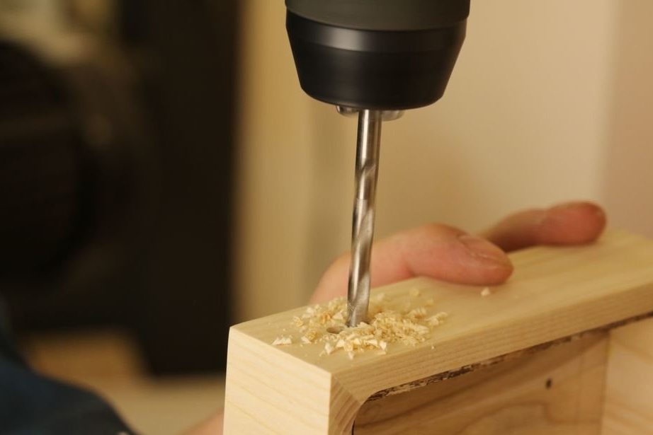
Using a template, makes markup. Drills, according to marks, a 3 mm drill, then slightly drills holes for magnets. A hole for a diffuser is drilled in the center of the workpieces.
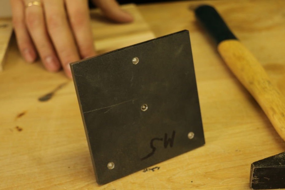
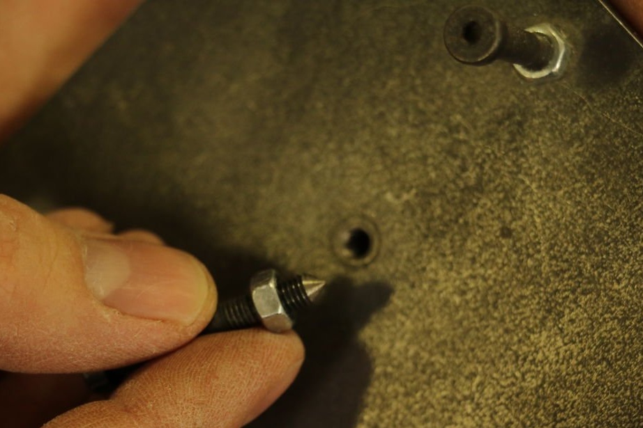
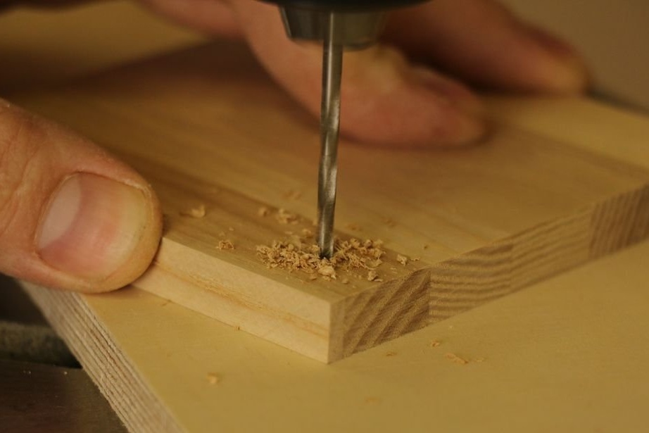
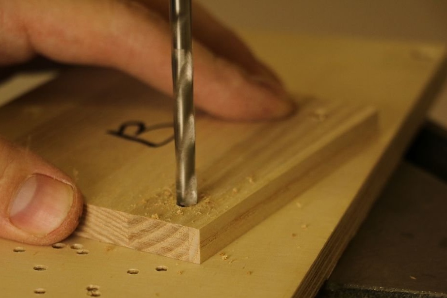
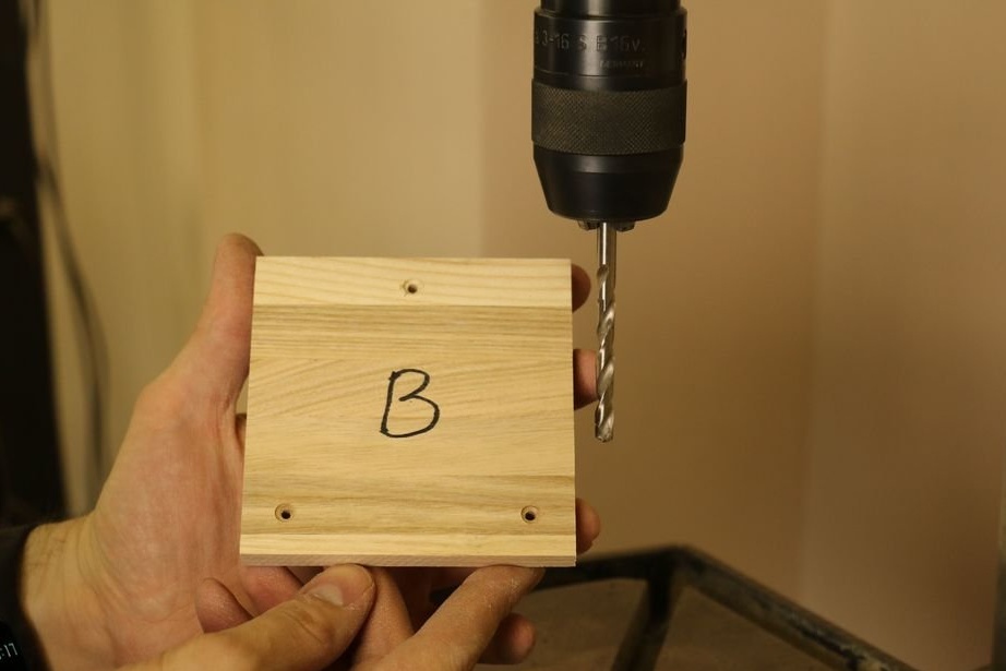
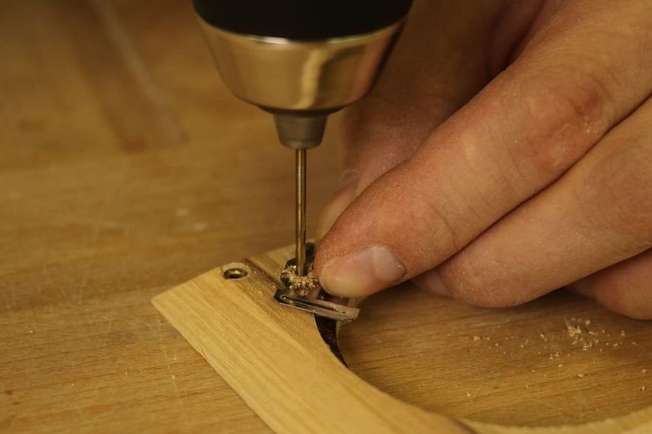
Drills four holes for metal mounts.
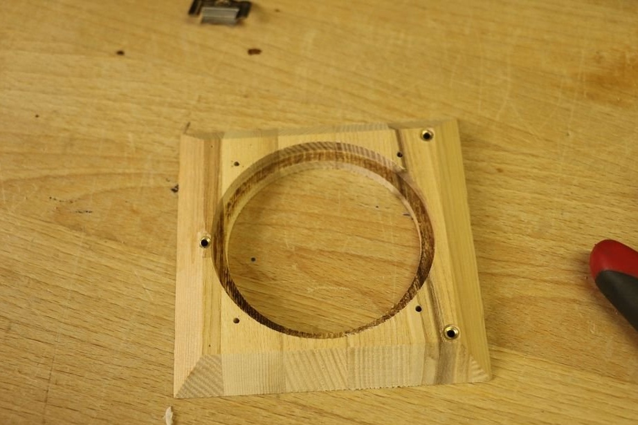
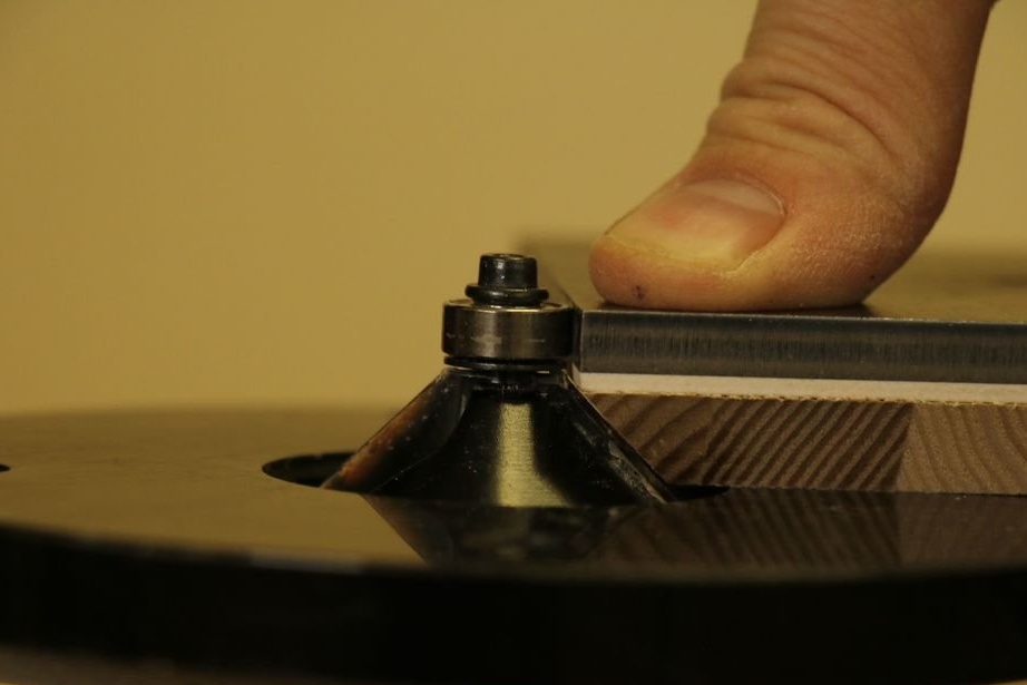
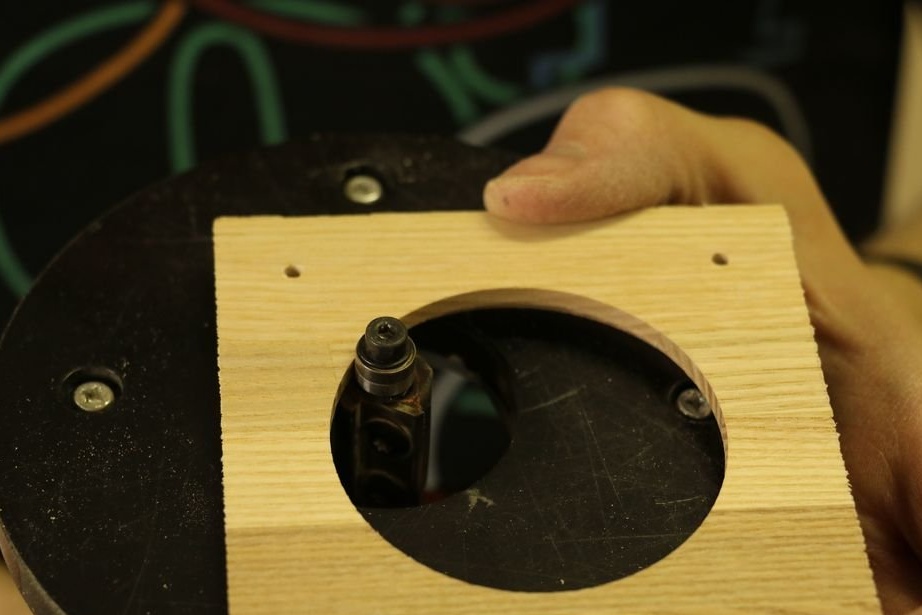
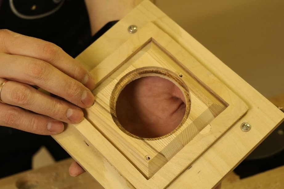
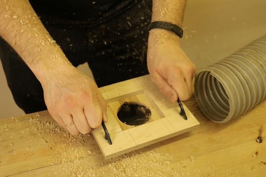
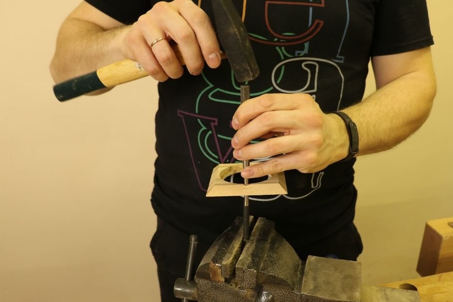
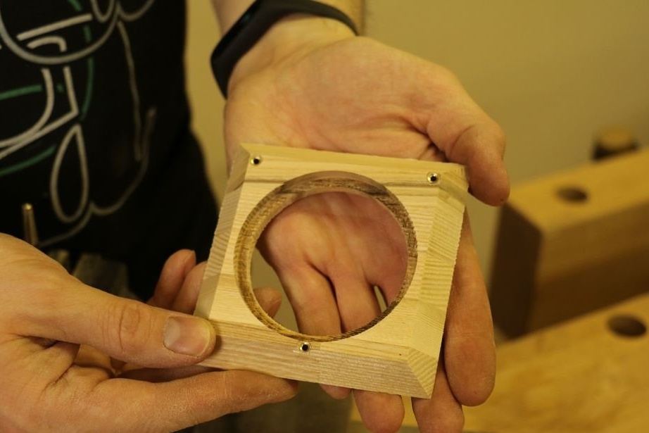
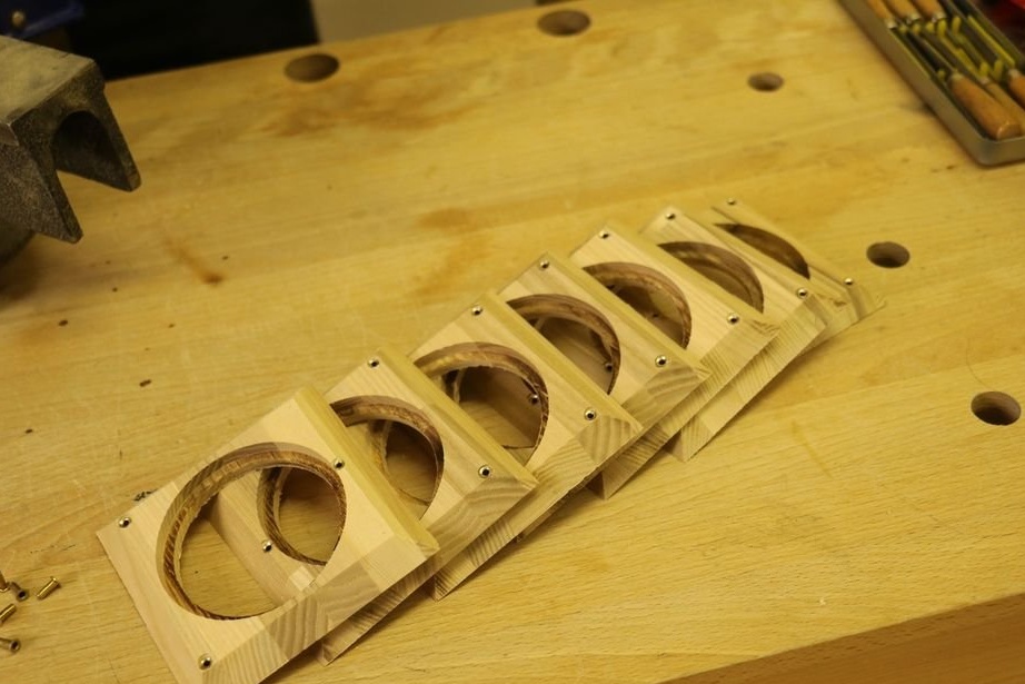
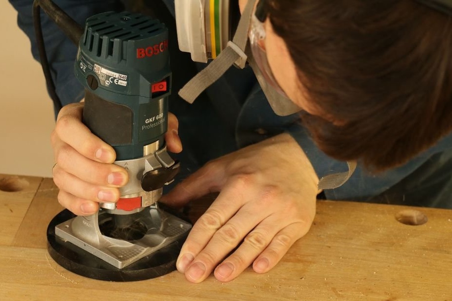
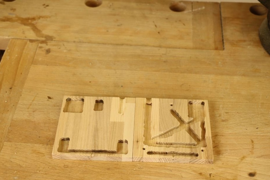
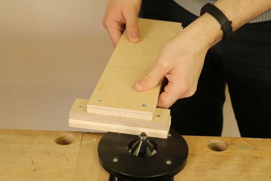
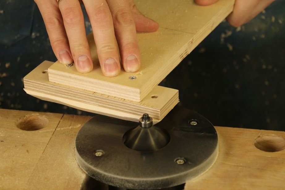
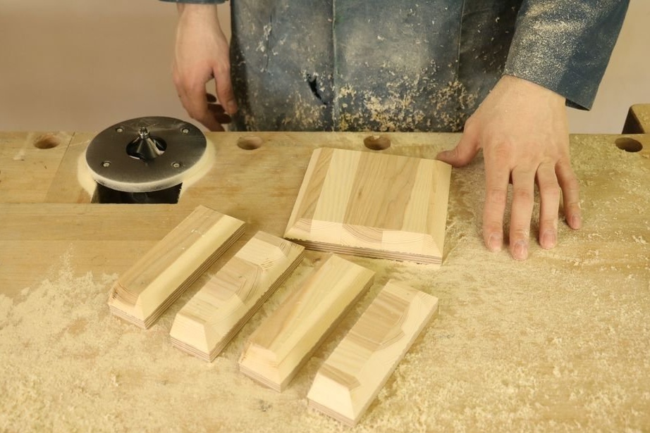
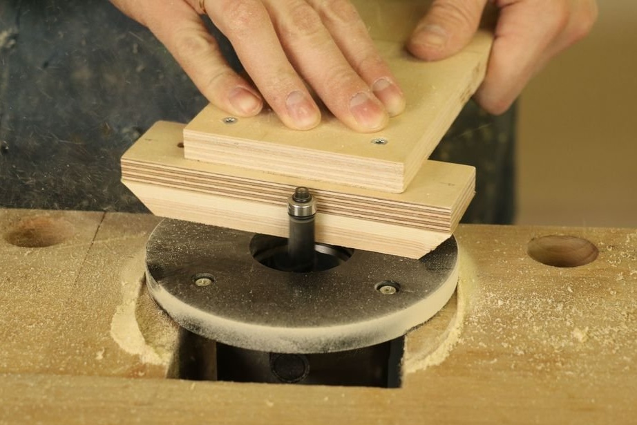
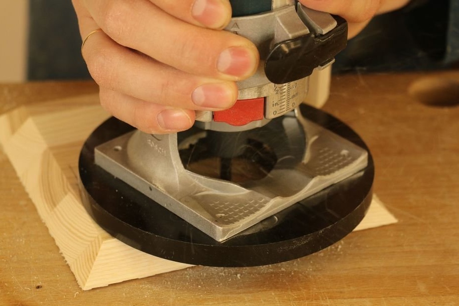
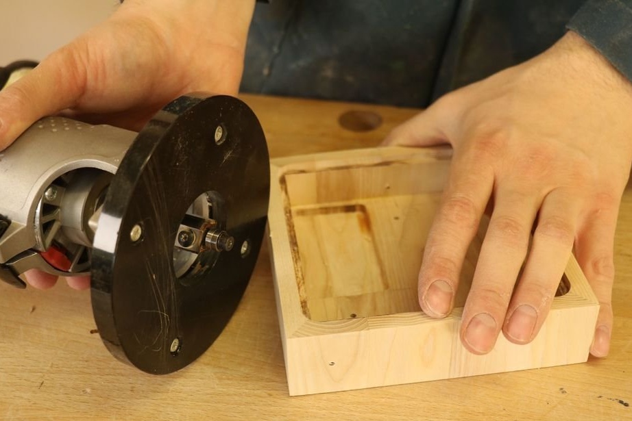
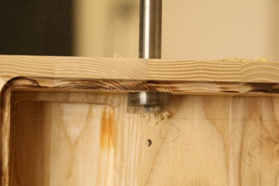
Using another template, mills the walls of the workpieces at 45 degrees.
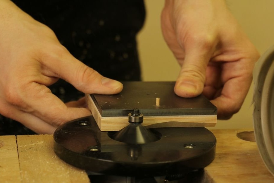
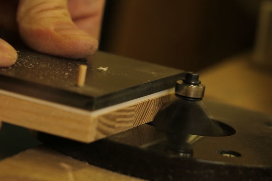
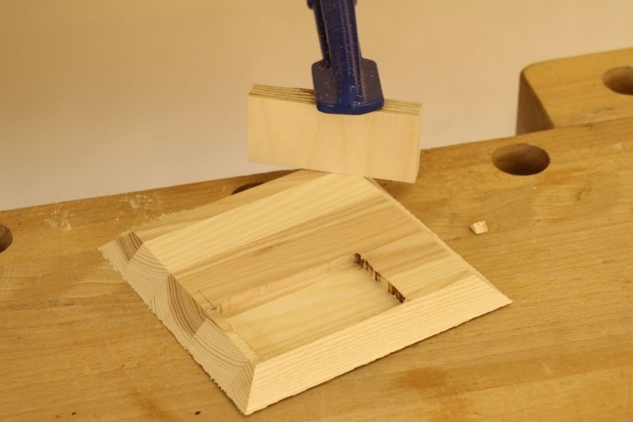
Mills the seat under the diffuser.
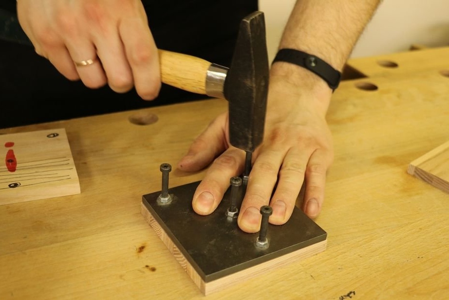
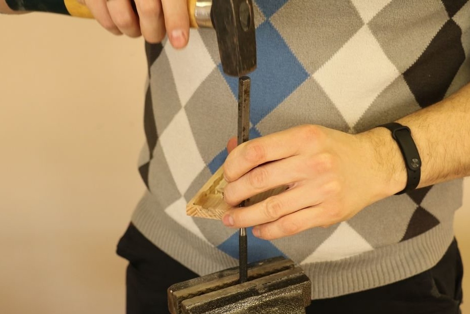
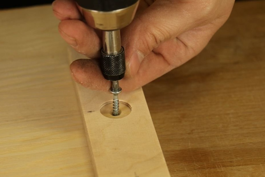
Step Three: Install Rivets
Sets rivets.
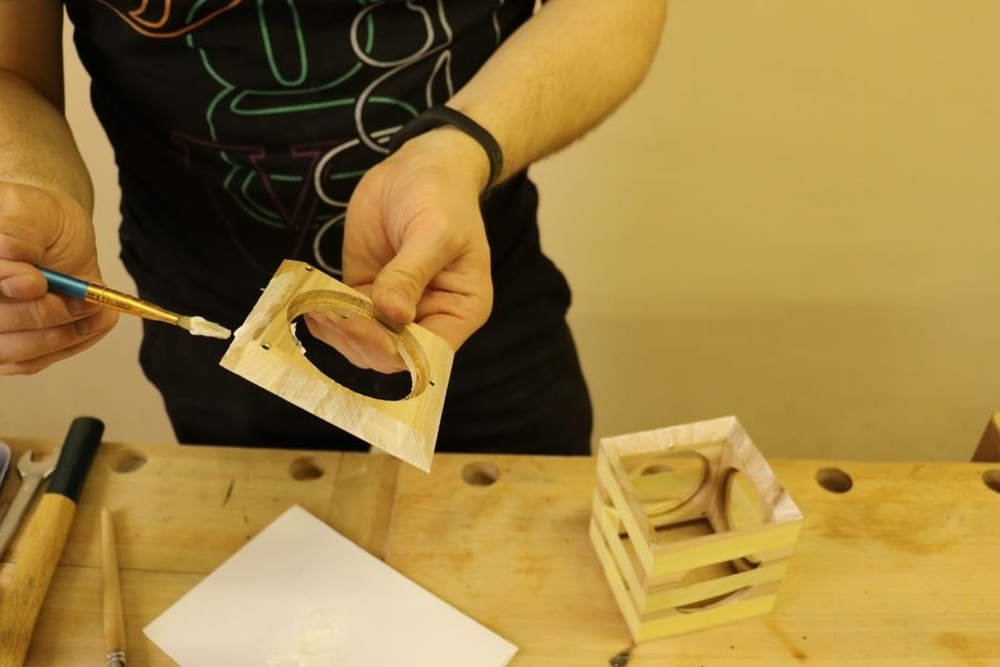
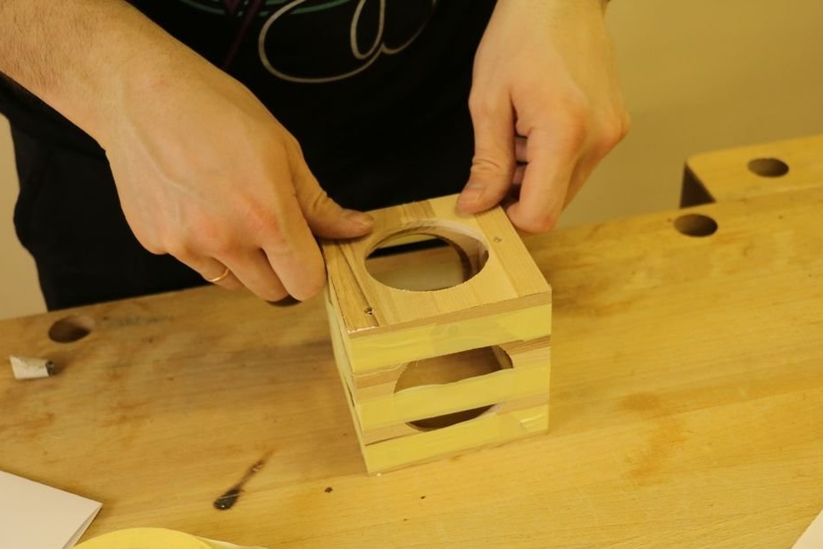
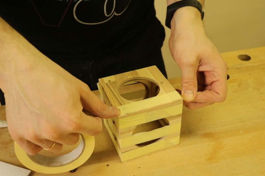
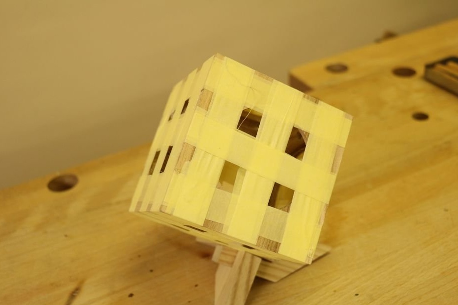
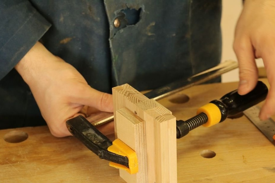
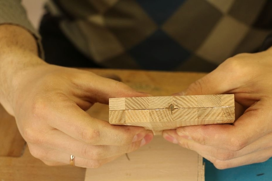
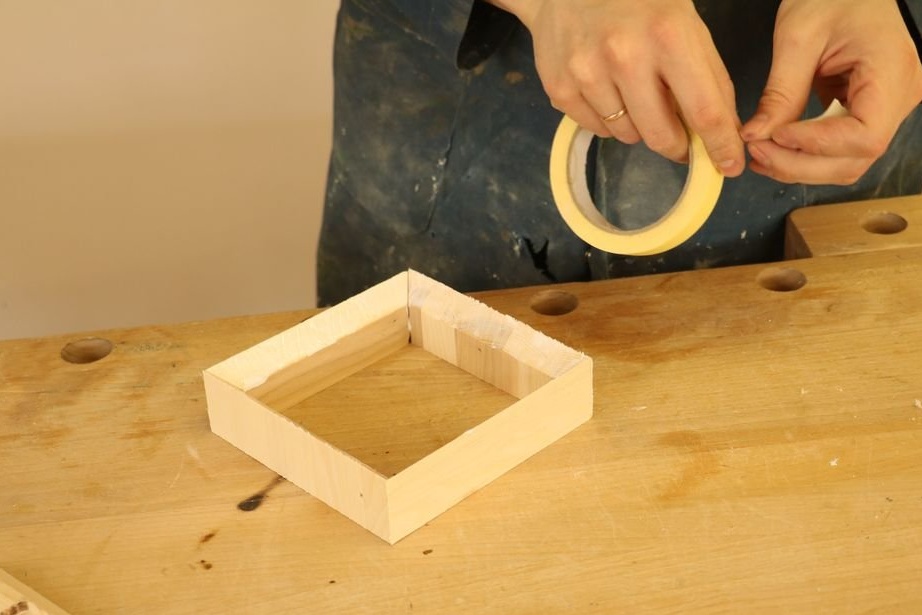
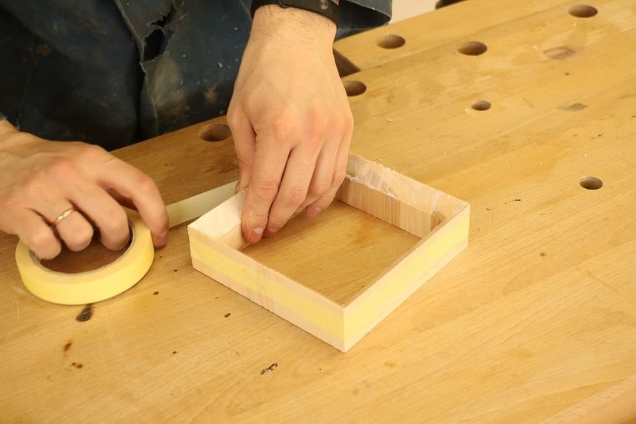
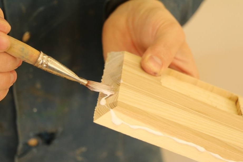
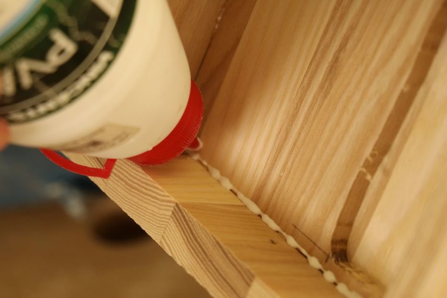
Step Four: Bonding the Block
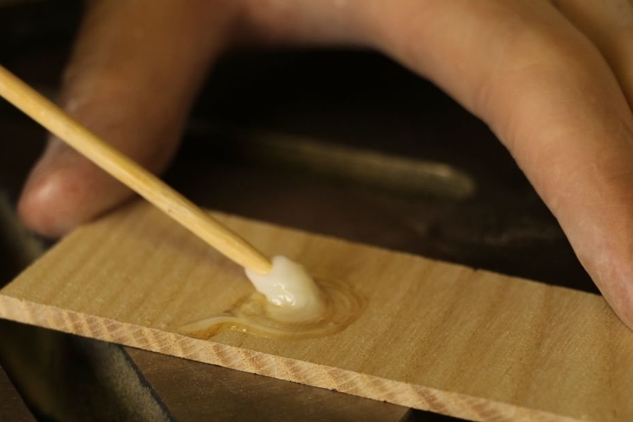
Now you need to glue the block.The master puts on the face of five blanks of the block (one blank is not yet glued) carpentry glue and fixes the cube with adhesive tape until it dries.
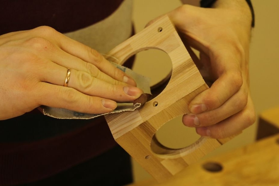
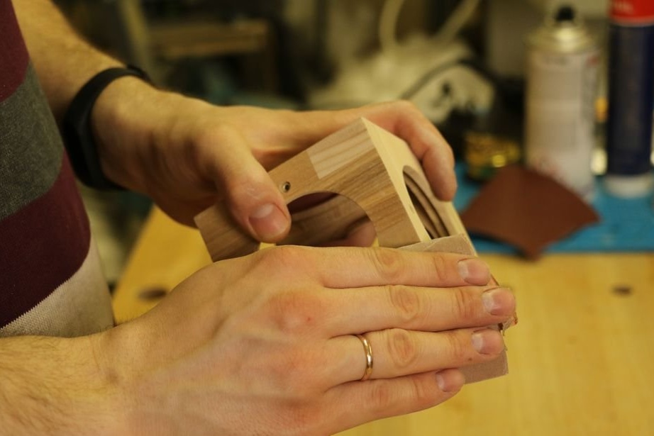
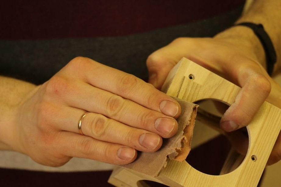
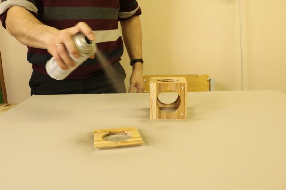
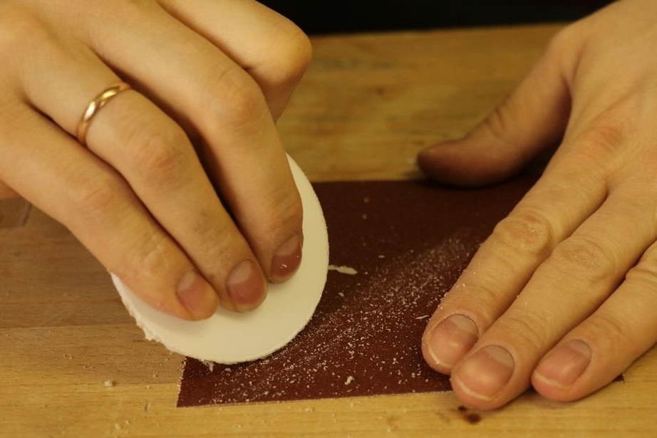
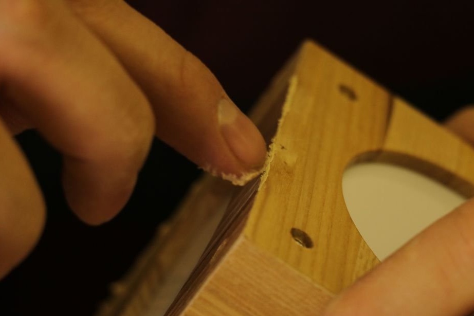
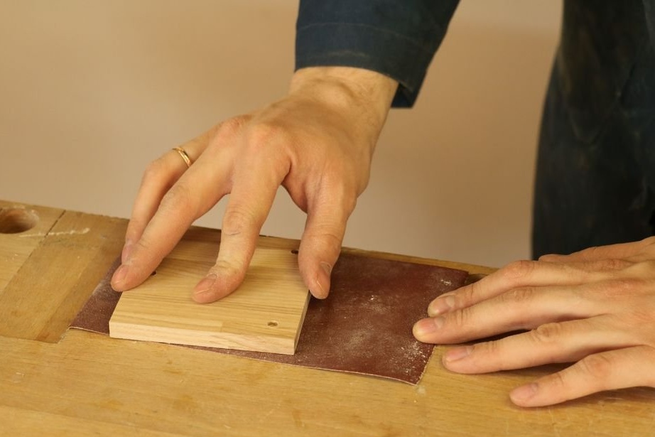
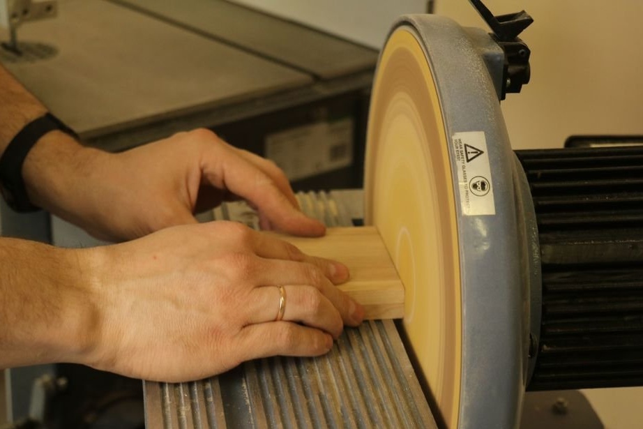
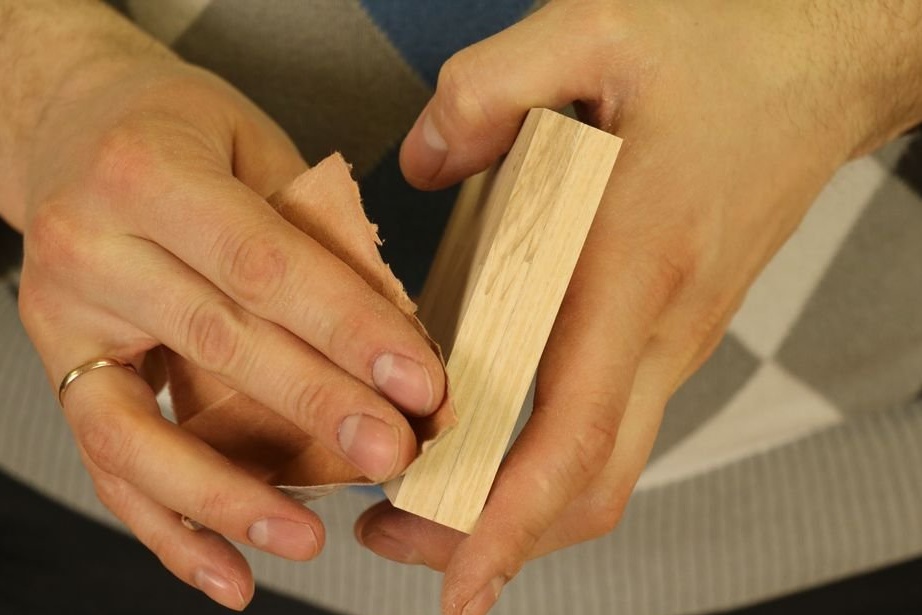
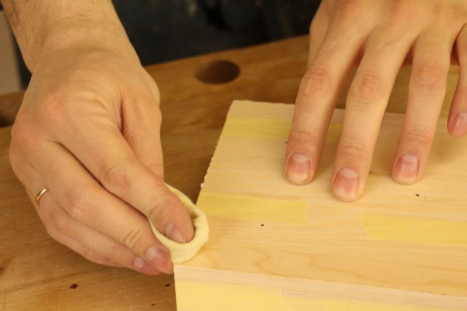
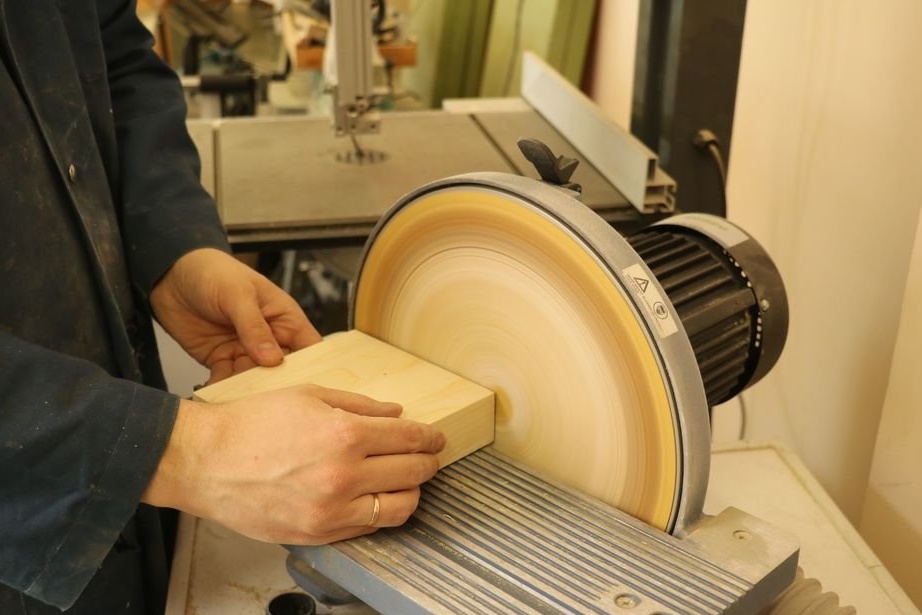
Step Five: Sanding, Varnishing
After gluing, the block must be sanded with 200 grit sandpaper. Putty and sand again.
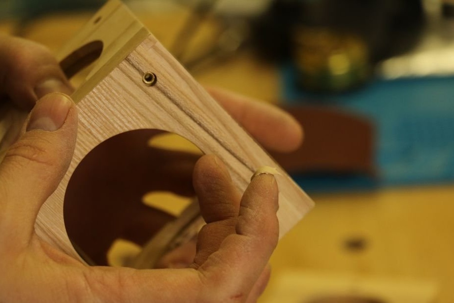
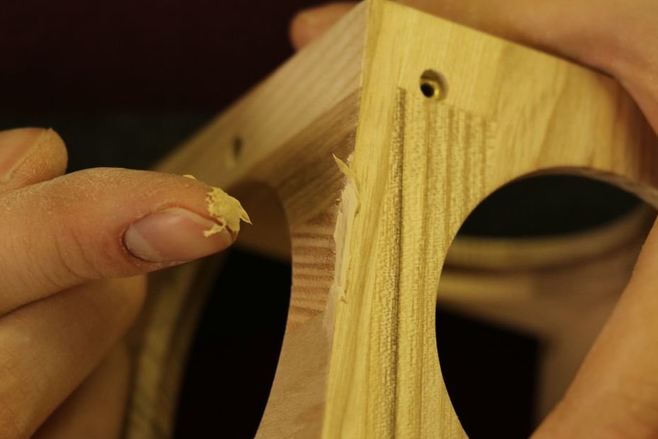
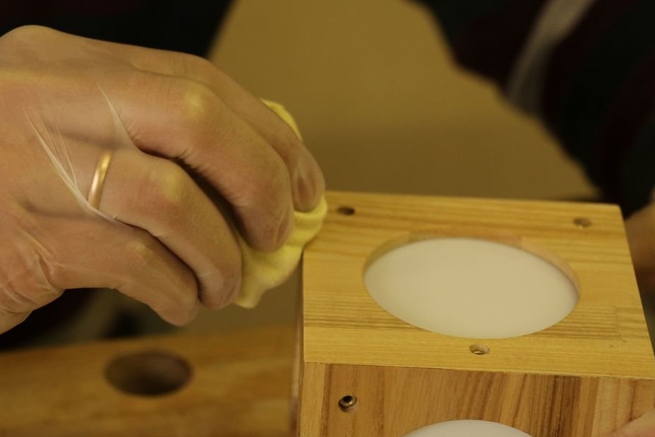
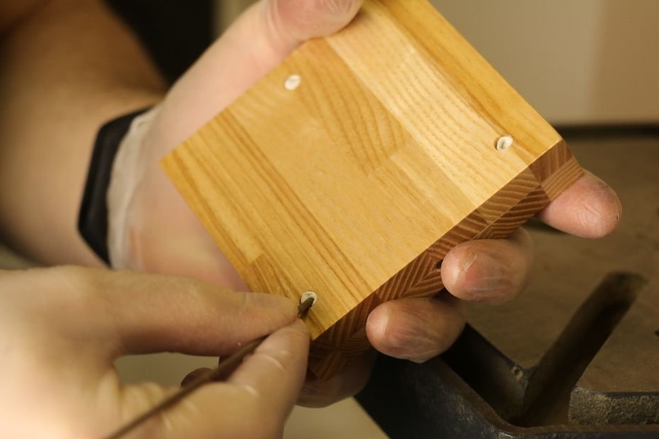
Now you need to close the rivets from getting varnish on them.
Covers the walls of the block with varnish in three layers and removes the protection.
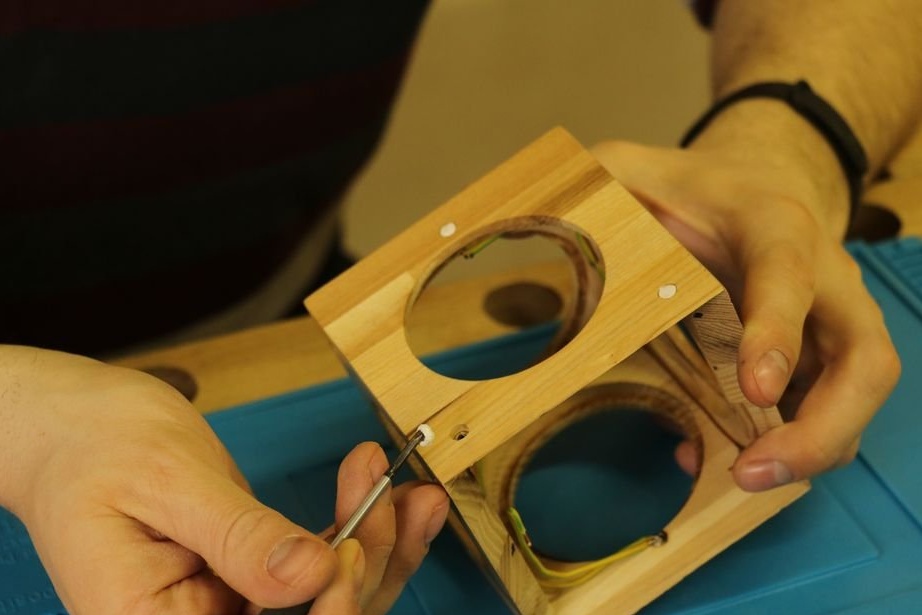
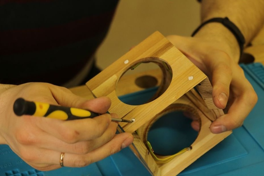
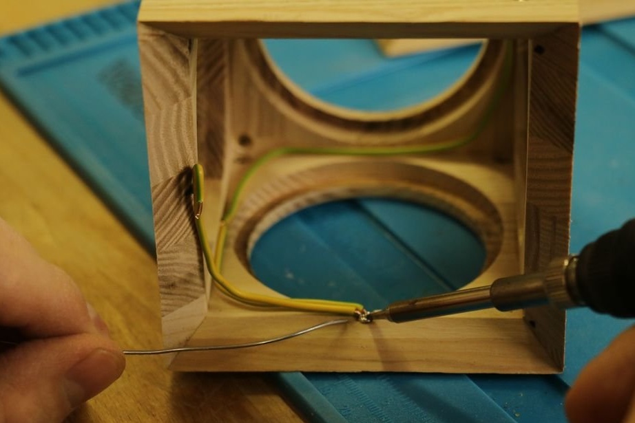
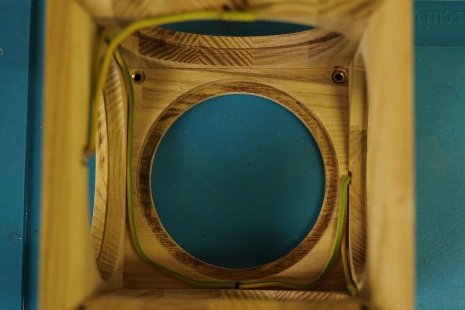
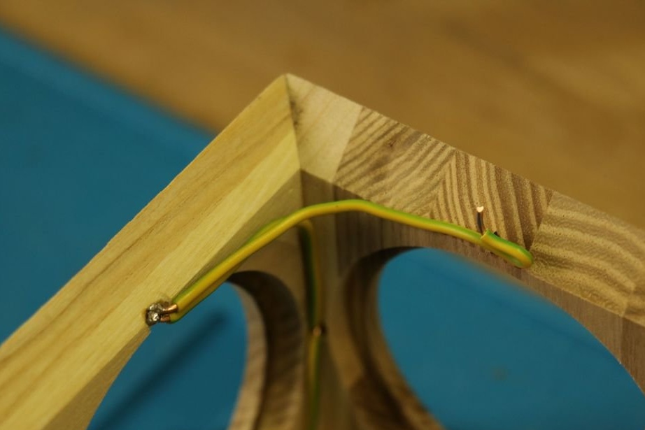
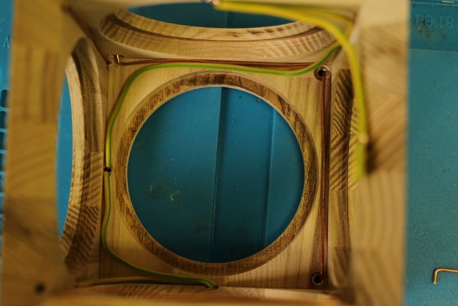
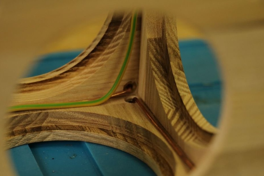
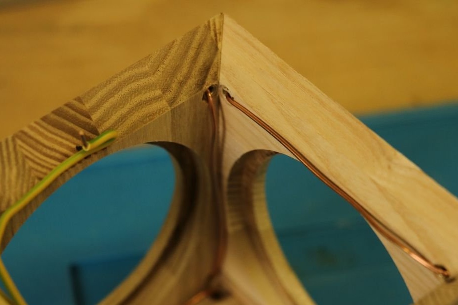
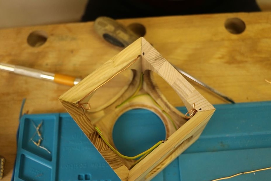
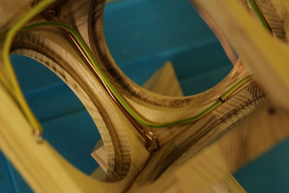
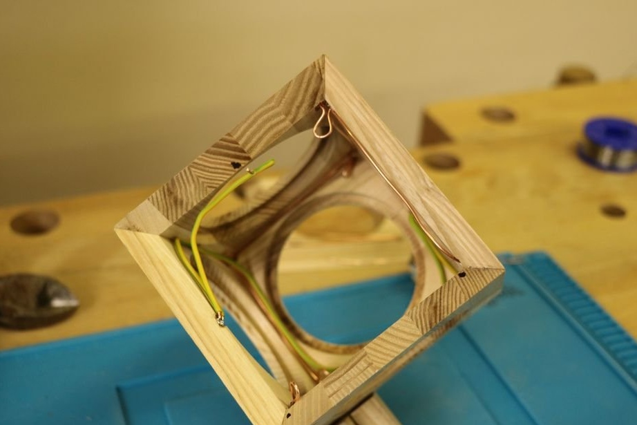
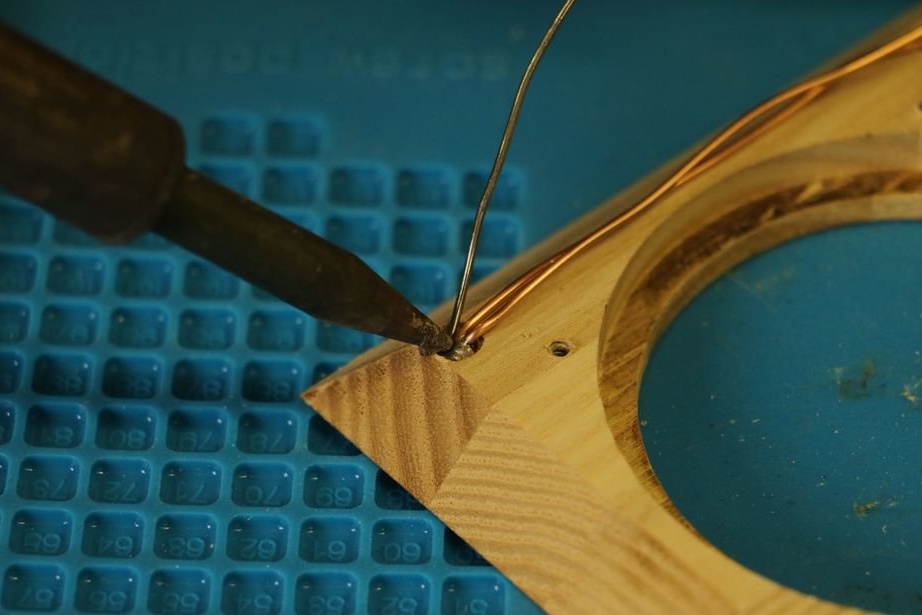
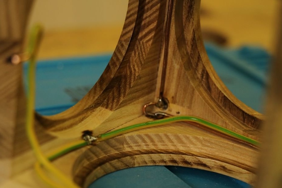
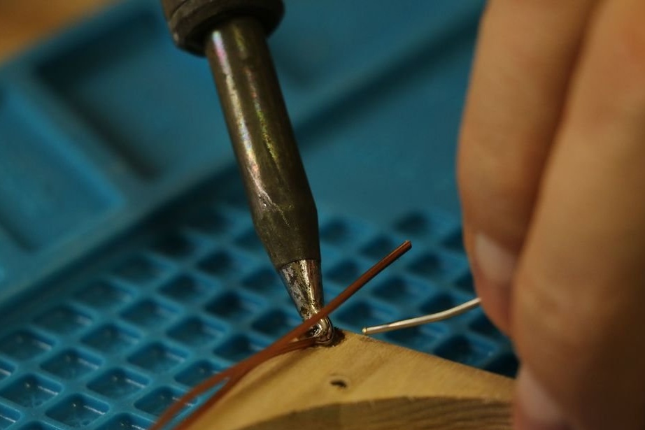
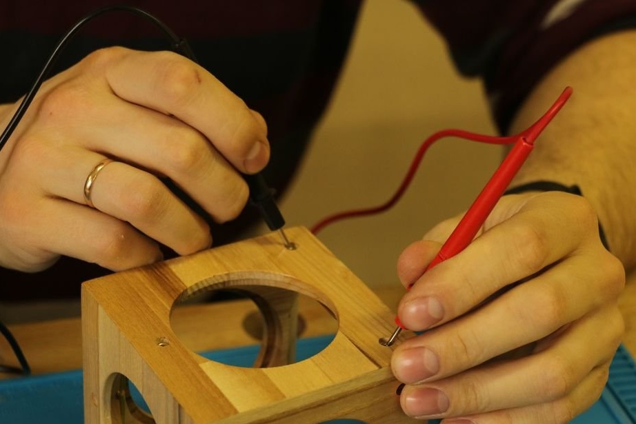
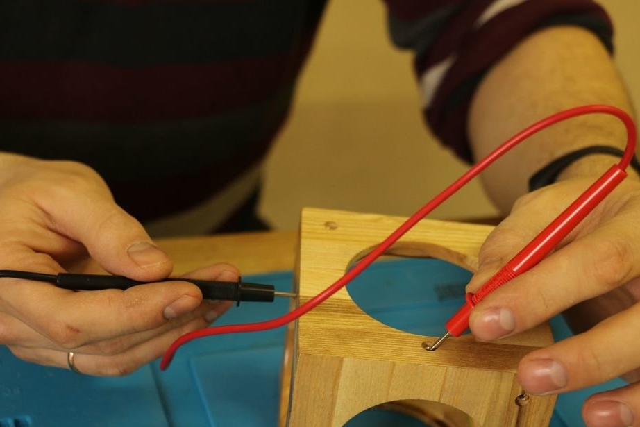
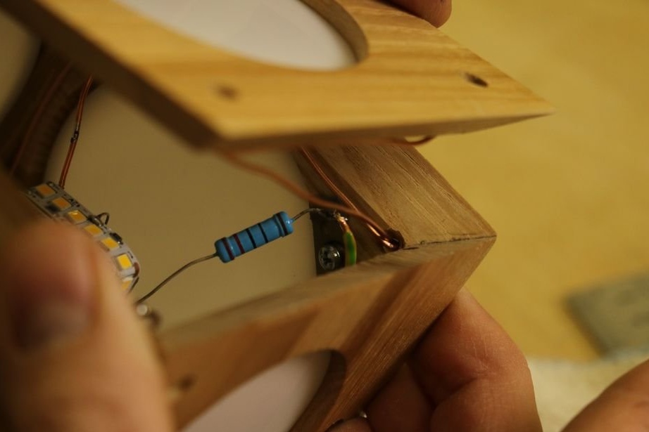
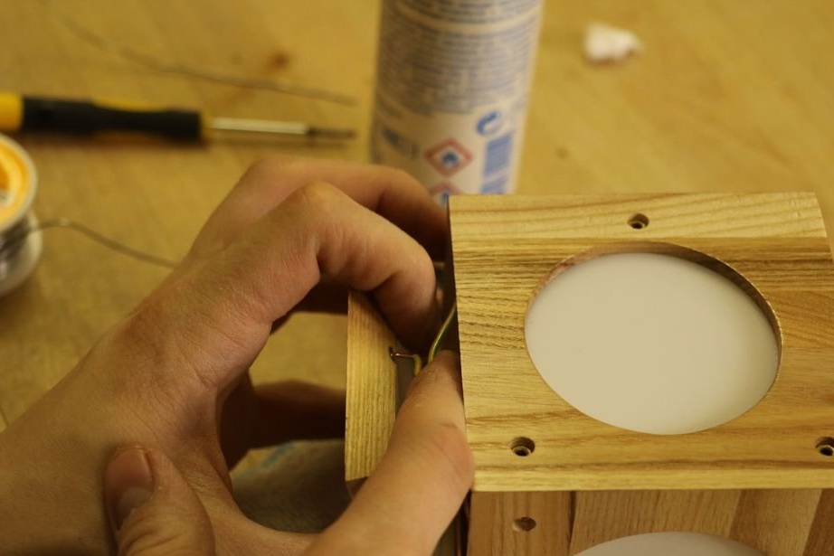
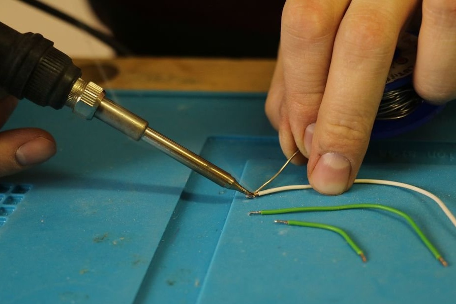
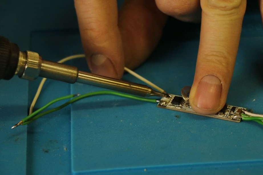
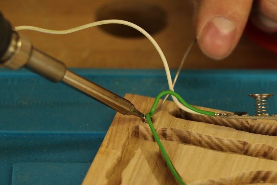
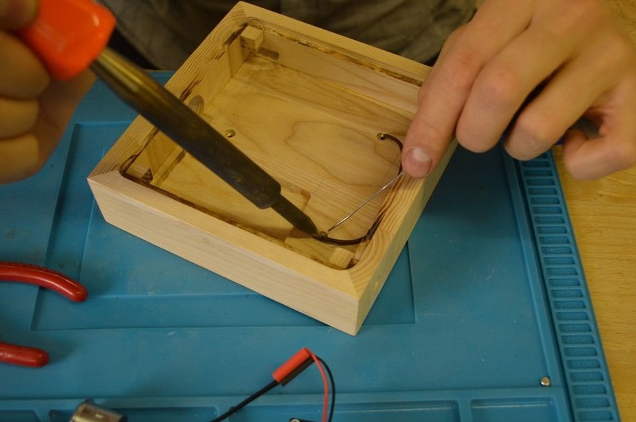
Step six: wire preparation and pre-soldering
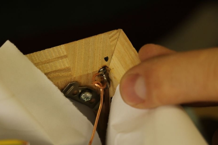
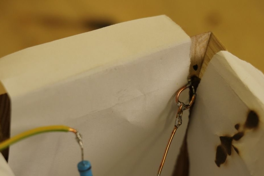
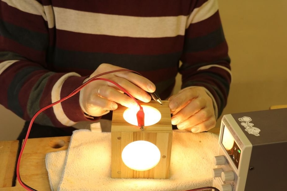
At this stage, you need to solder the wire to the rivets. All wire lengths are approximate and subject to change, so don’t hesitate and see what is right for you.
The master removes insulation from the negative wire. It is necessary to connect all the plus and minus rivets with wires. In this case, the plus will be where one rivet stands, and the minus where two.
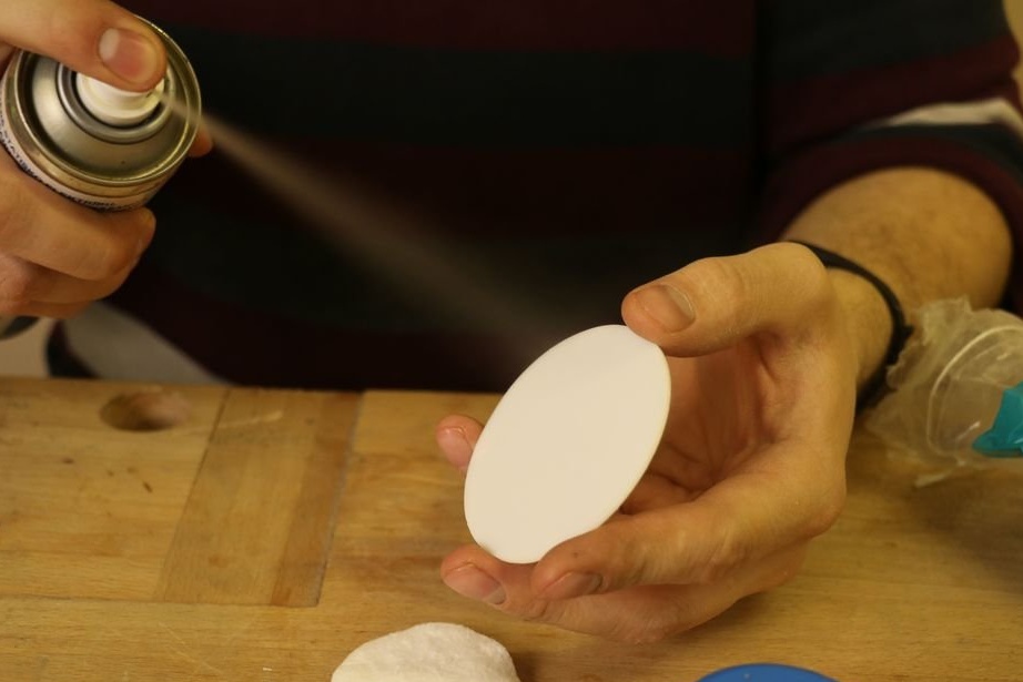
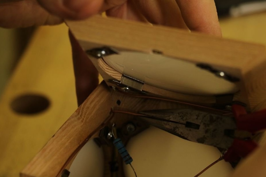
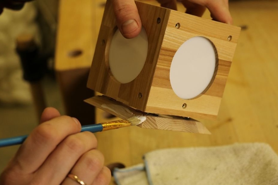
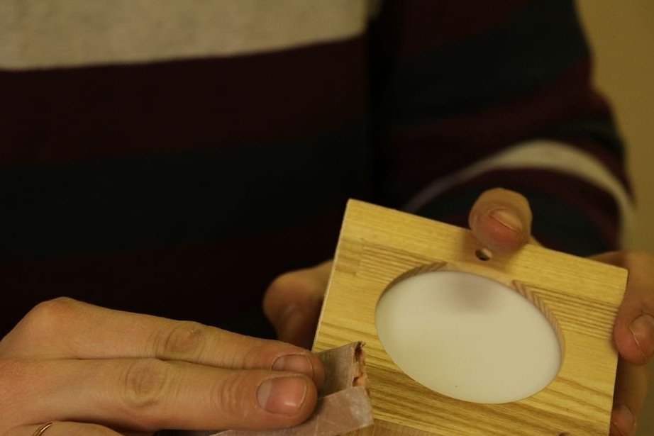
Seventh step: diffuser
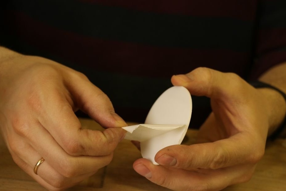
A crown cuts out diffusers from acrylic.
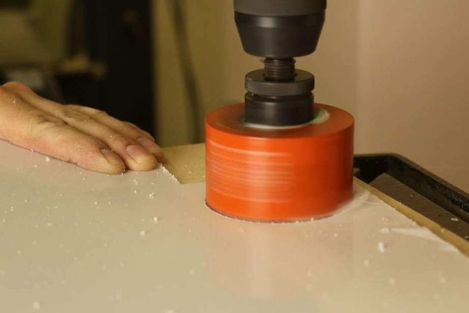
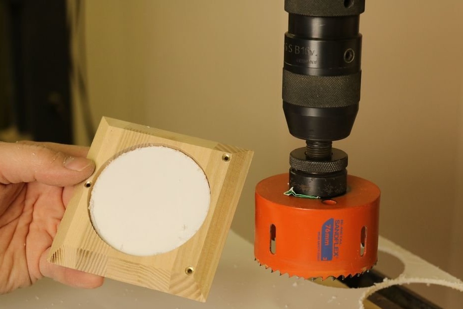
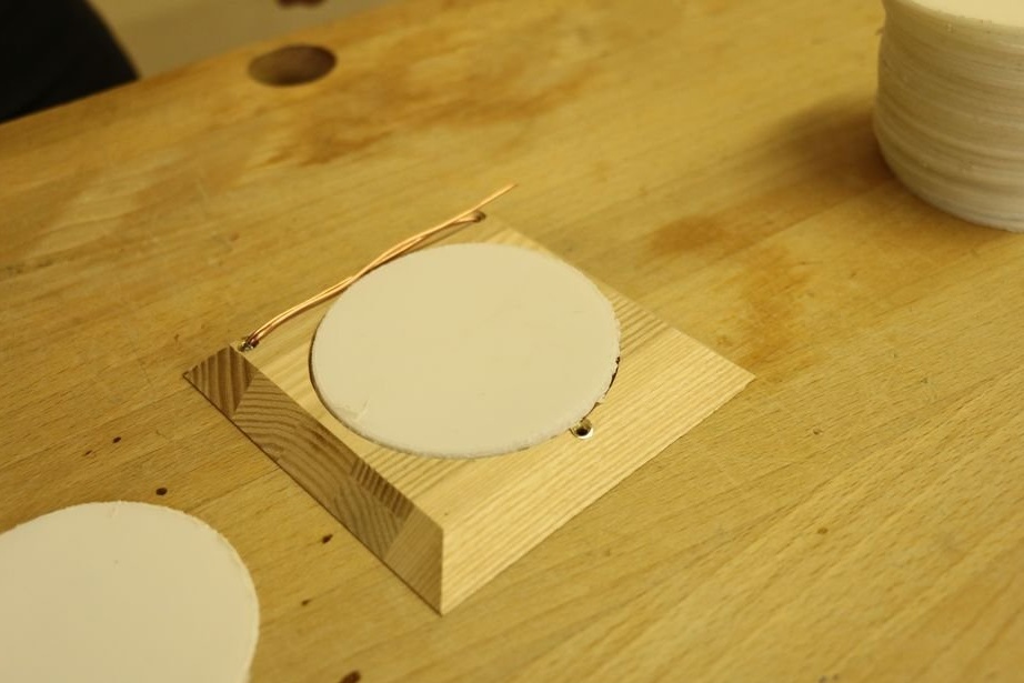
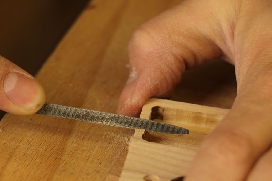
Grinds the edges.
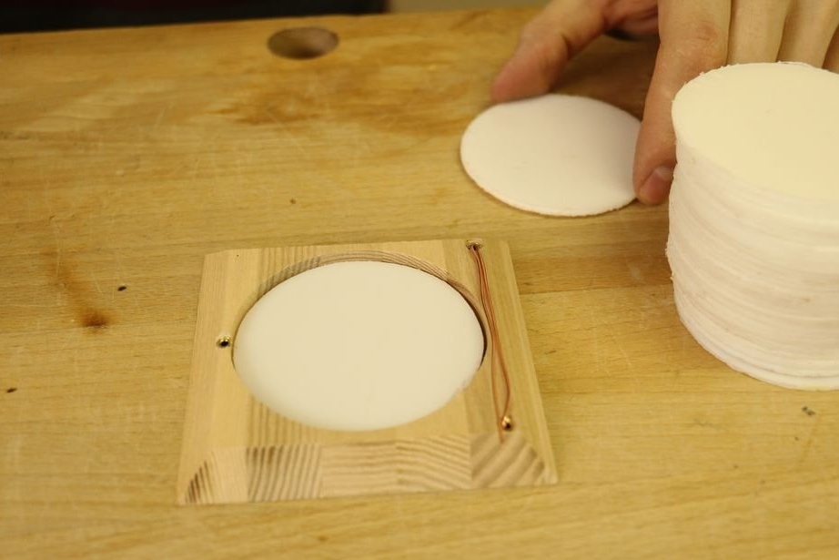
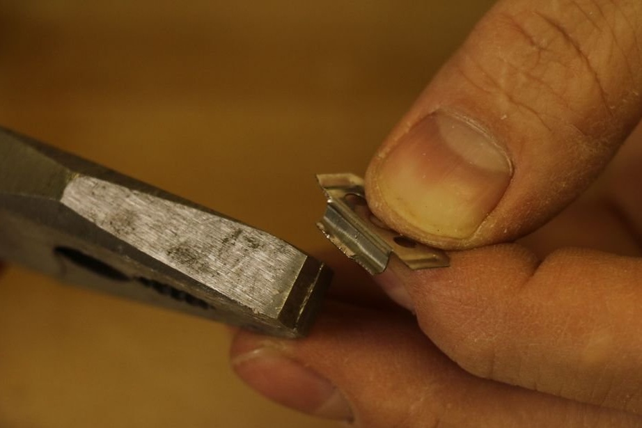
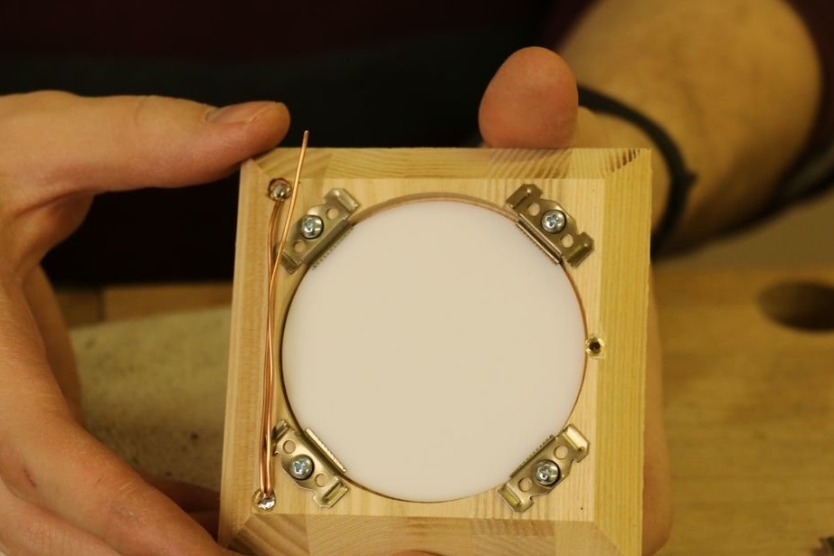
Prepares mount.
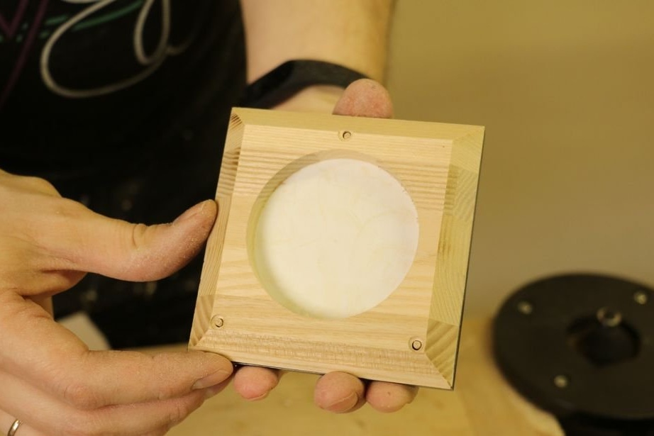
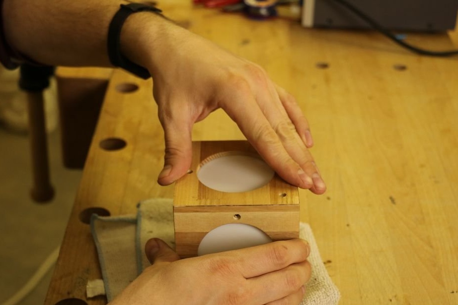
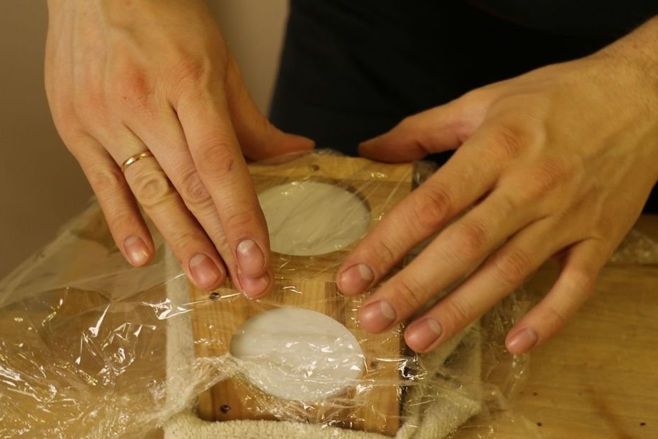
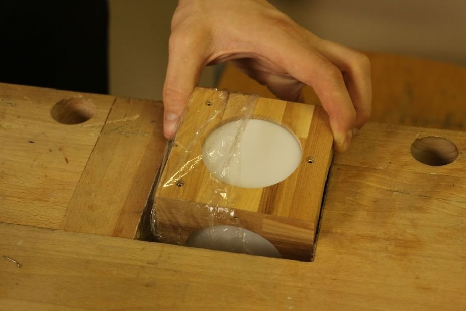
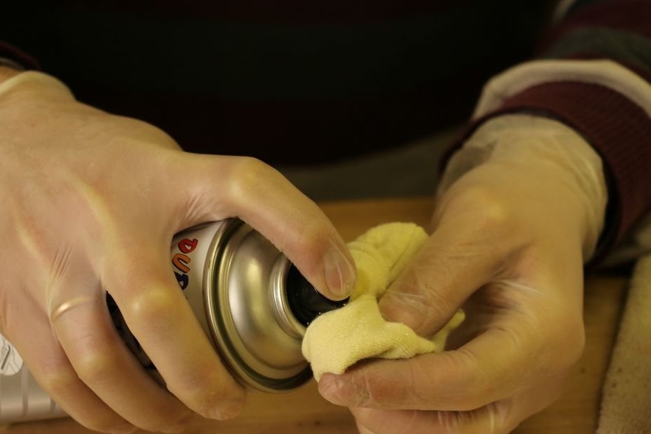
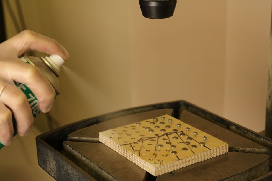
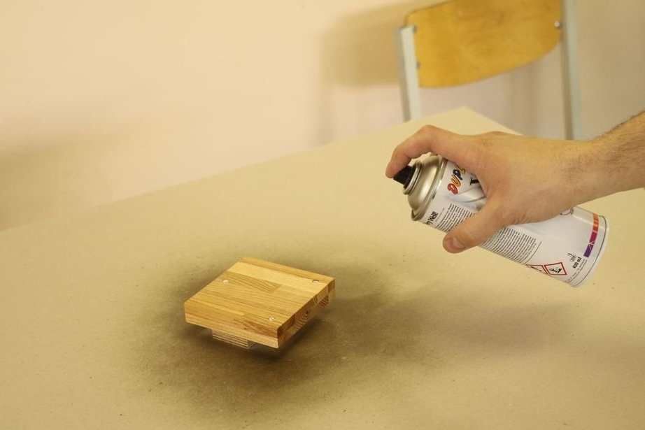
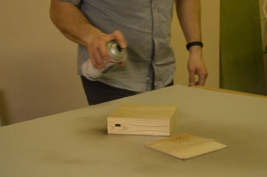
Removes a protective film from acrylic. Applies antistatic spray on both sides. Installs and fixes diffusers.
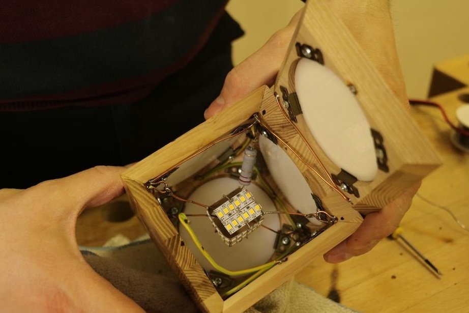
Step Eight: LEDs
Now you need to prepare and install the LEDs.
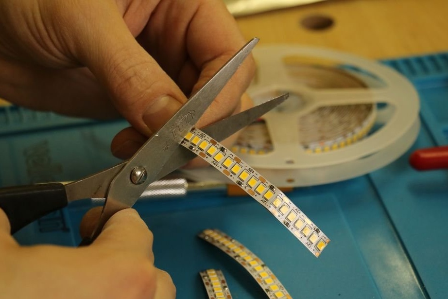
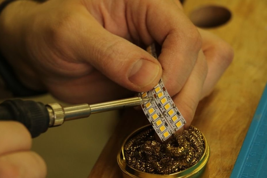
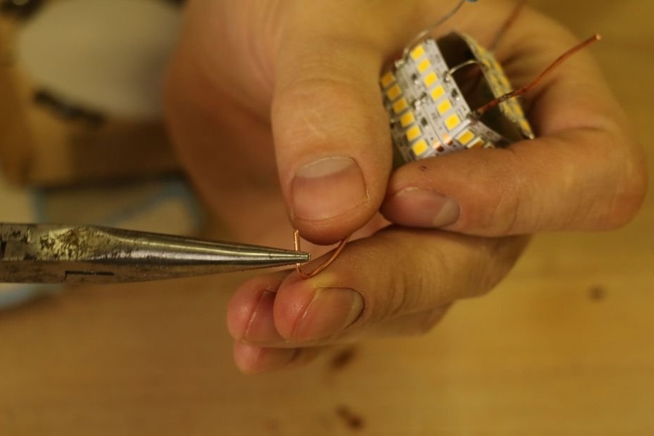
Cuts the LED strip into 18 LEDs. For each cube, 4 such strips are needed.
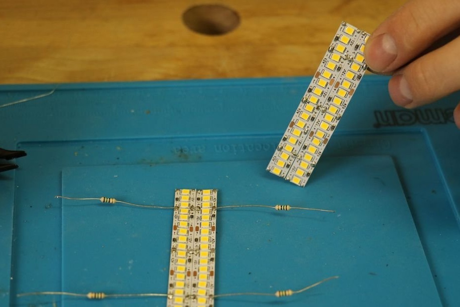
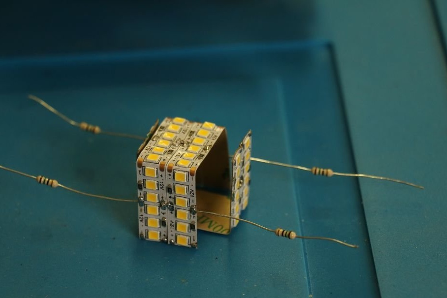
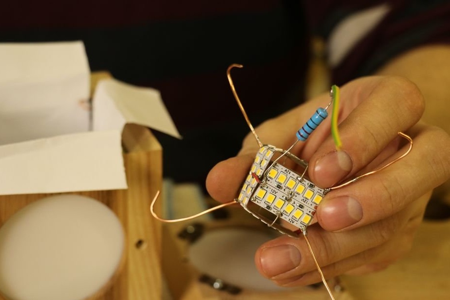
It solves them in two pieces so that the “+” is in the middle, and the “-” is outside. Solder 4 resistors.
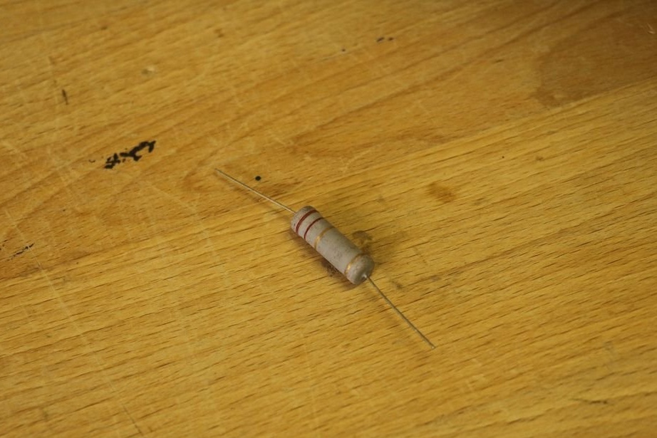
From the author: as far as I understand, the resistors here are used only as connectors, or rather not resistors, but the wire at the ends of the resistors, and the resistors themselves are removed.
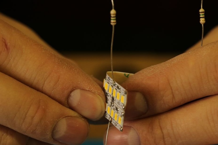
It bends the LED strip with the letter P (12 LEDs on each side).
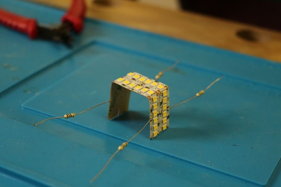
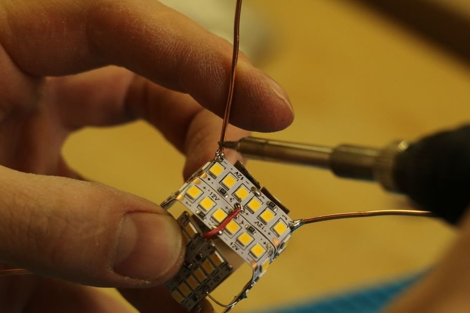
Folds the strips "cube" and solders + one to + another, minus to minus.
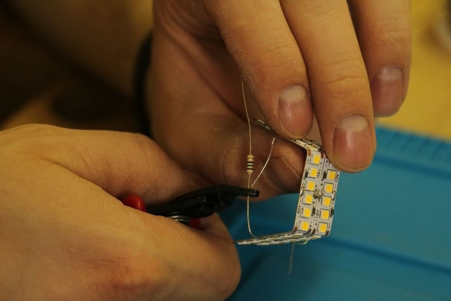
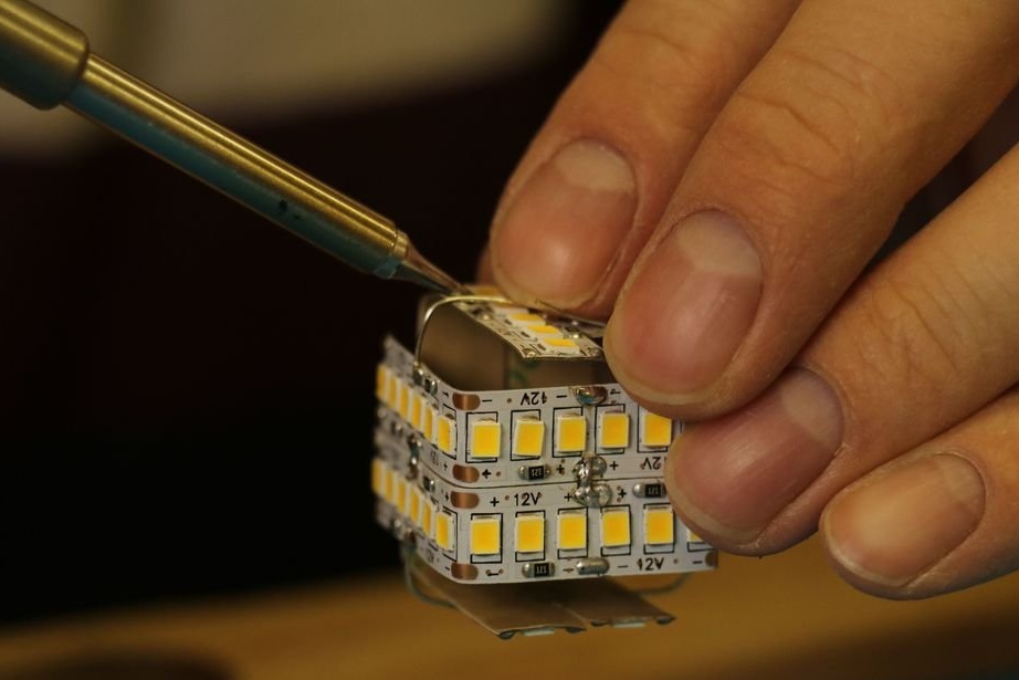
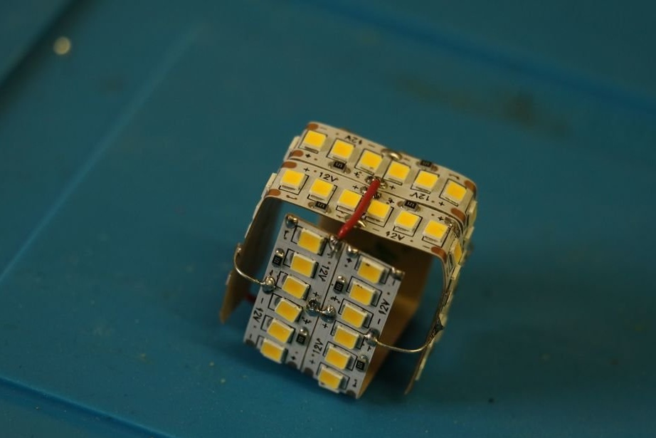
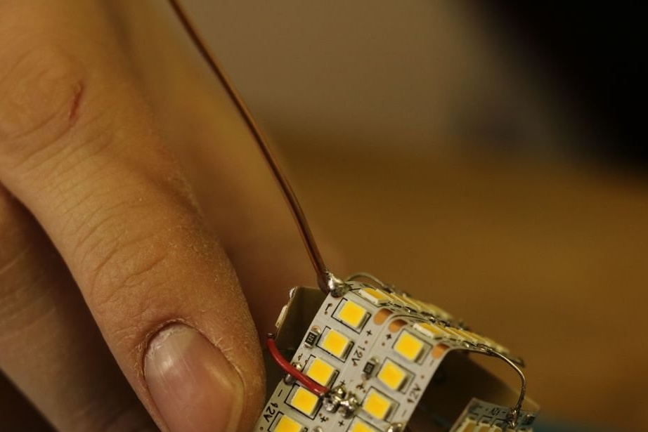
Solder the cross to the cross two wires minus the LEDs. Solder wire to + LEDs. A 2.2 ohm resistor is soldered to the positive wire.
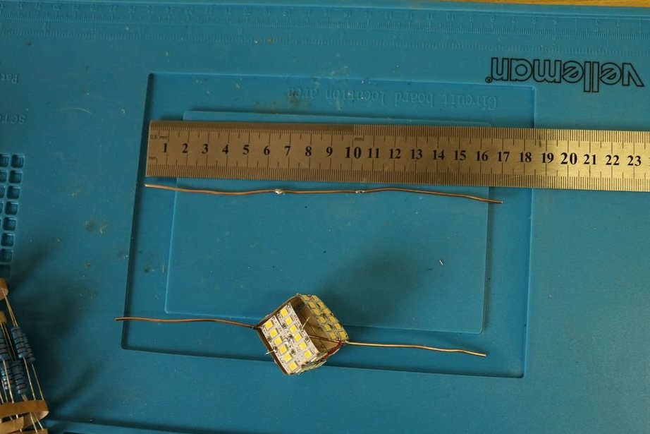
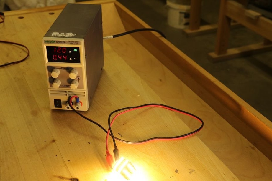
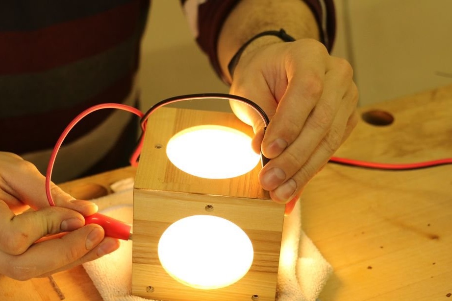
It connects the power source and checks the operation of the LEDs.
Now you need to install the assembled LED cube inside the wooden cube.
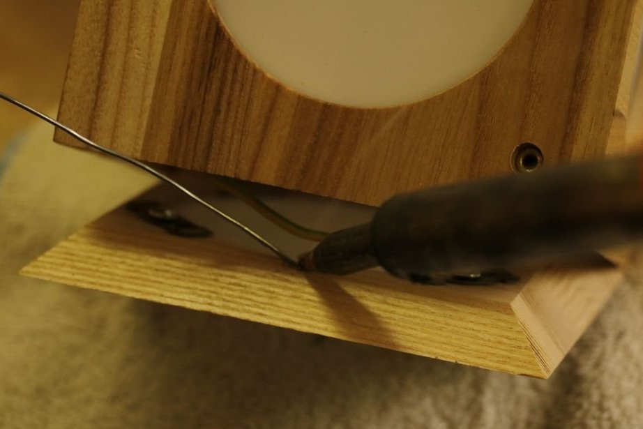
So that the solder does not drip on the acrylic master, covers it with a strip of paper.
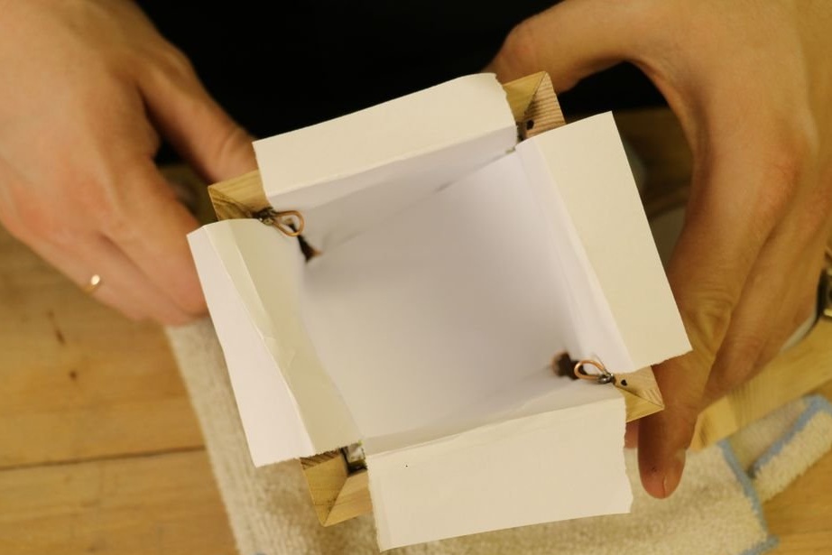
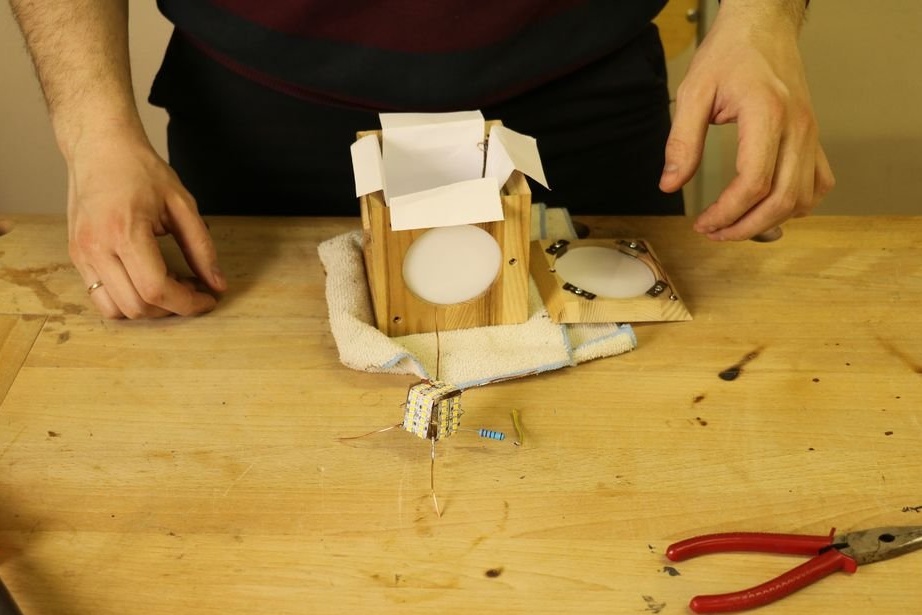
Sets the LED cube. Solder conclusions.
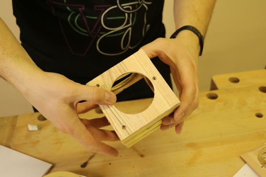
Removes paper and installs the sixth cube cover.
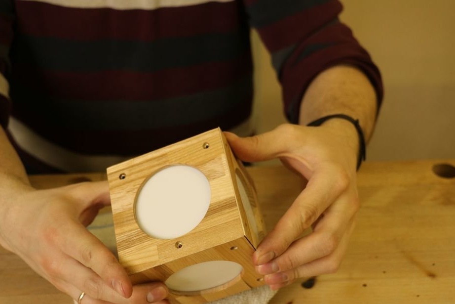
Step nine: testing, debugging
Before gluing the last panel, the wizard checks the operation of the LEDs. Then he glues the panel, putsty cracks, polishes.

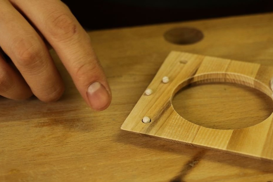
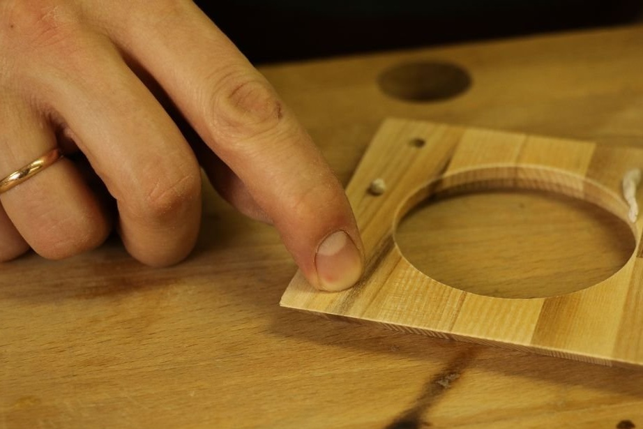
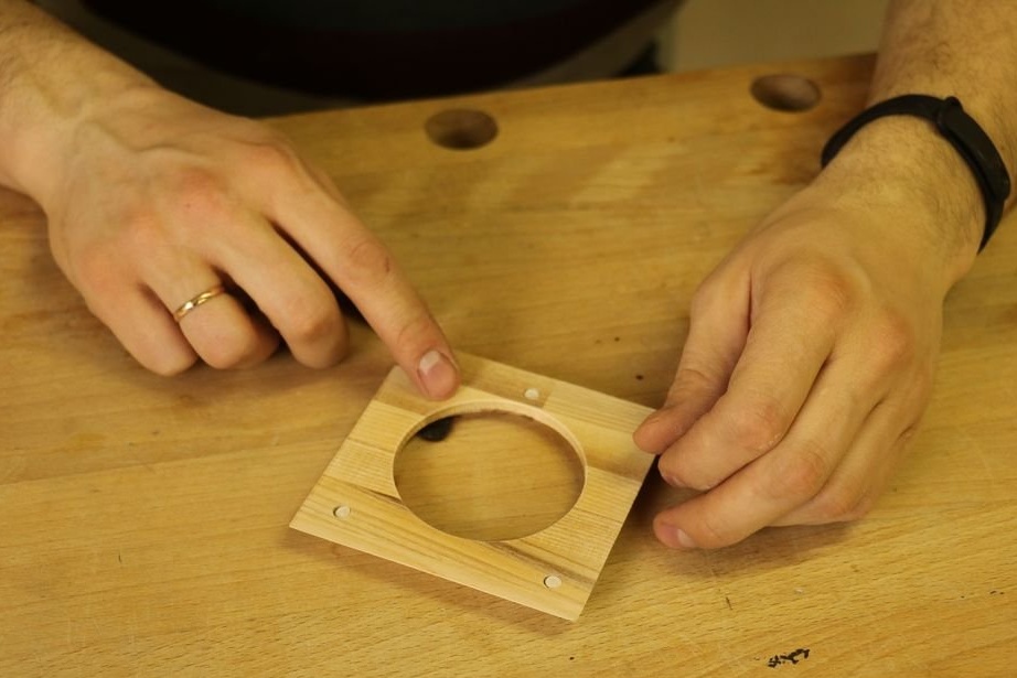
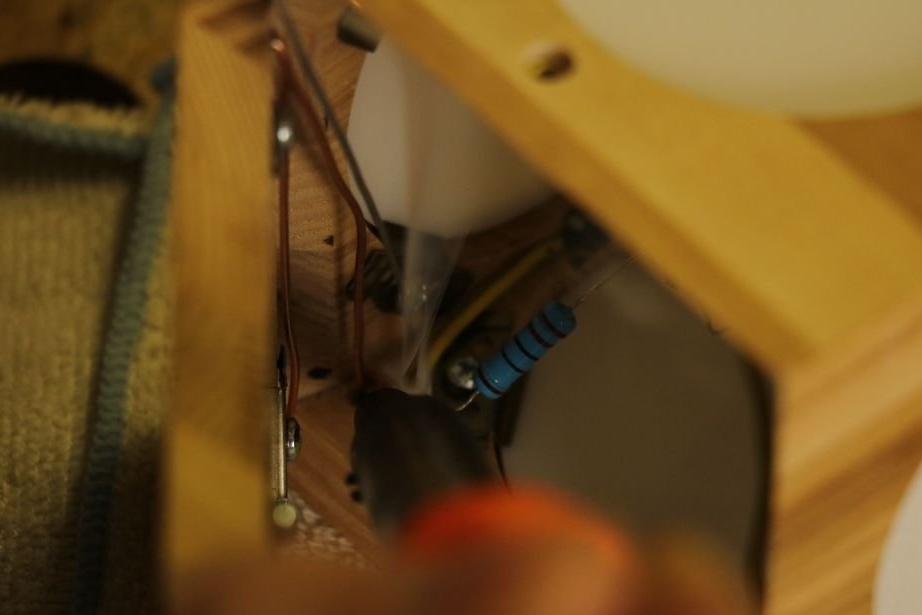
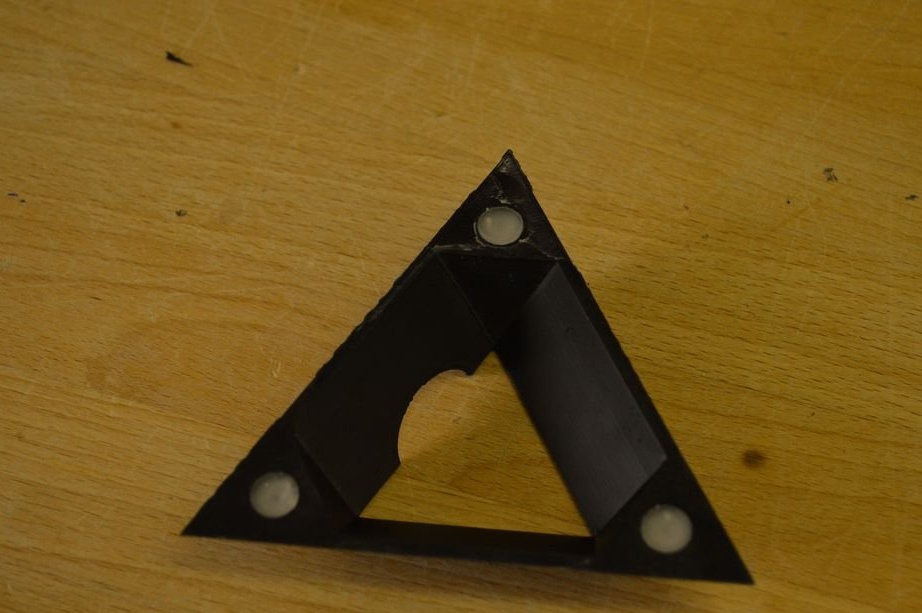
Step Ten: Install Magnets
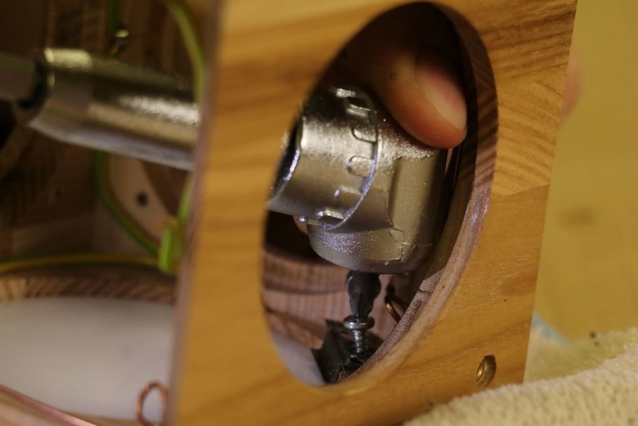
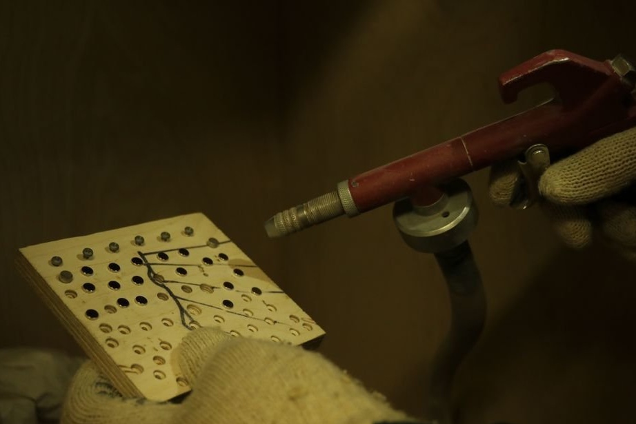
Now you need to glue 18 magnets. First, the master removes the upper protective layer by sandblasting. Divides magnets in poles in half. Then it puts epoxy in the hole.
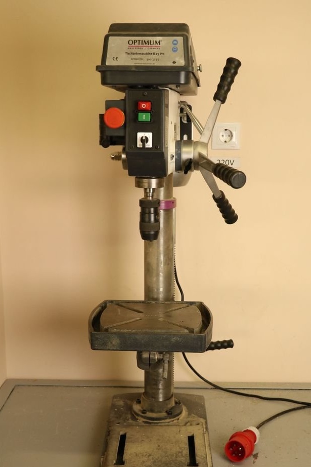
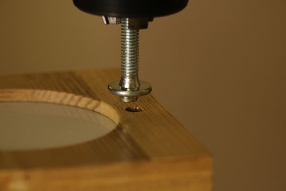
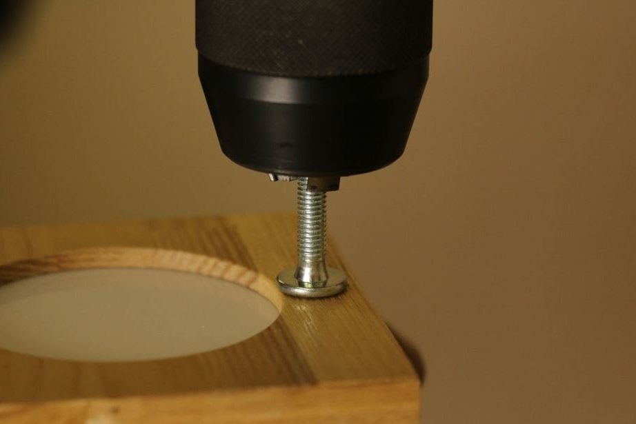
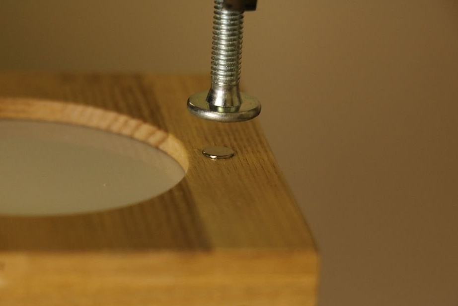
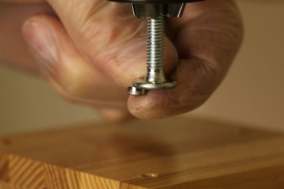
Then, using a drilling machine, presses the magnets into the hole. On one side there should be magnets of one pole, on the opposite of the other. Checks if the magnet is in contact with the rivet. If there is no contact, presses the magnet harder. The main thing is not to split the panel.

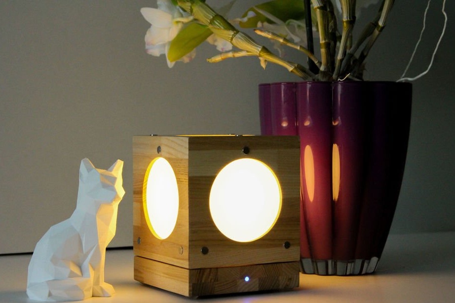
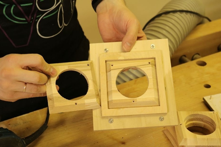
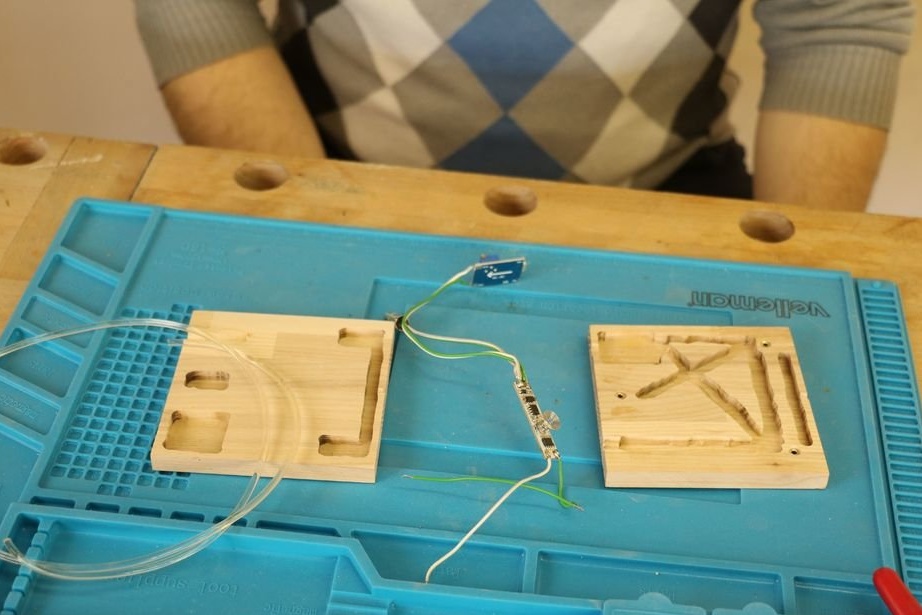
Step Eleven: Small Base
To supply cubes, the master makes three bases or bases: small (3 cubes), large (8 cubes) and 3D + adapter. In this step we will analyze the manufacture of a small base.
There is nothing complicated in the manufacture of a small base. The master prints a template and cuts the part from the template.
Below you can download files with templates.
Small_base_V9.f3d
maza_baze.pdf
maza_baze.dxf
maza_baze2.dxf
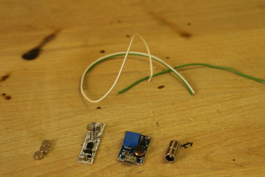
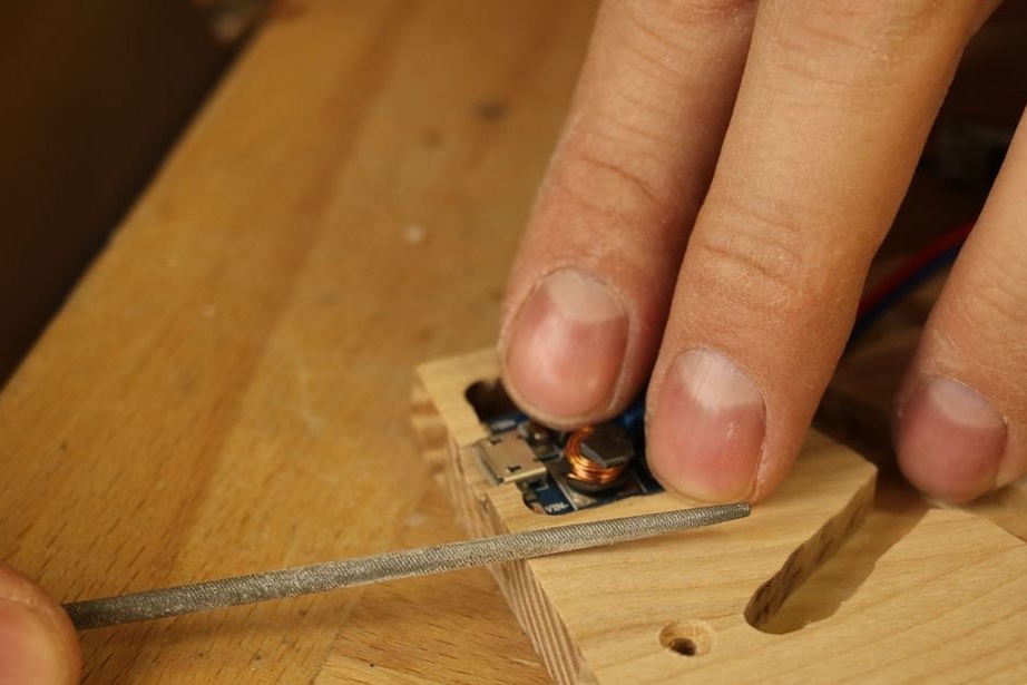
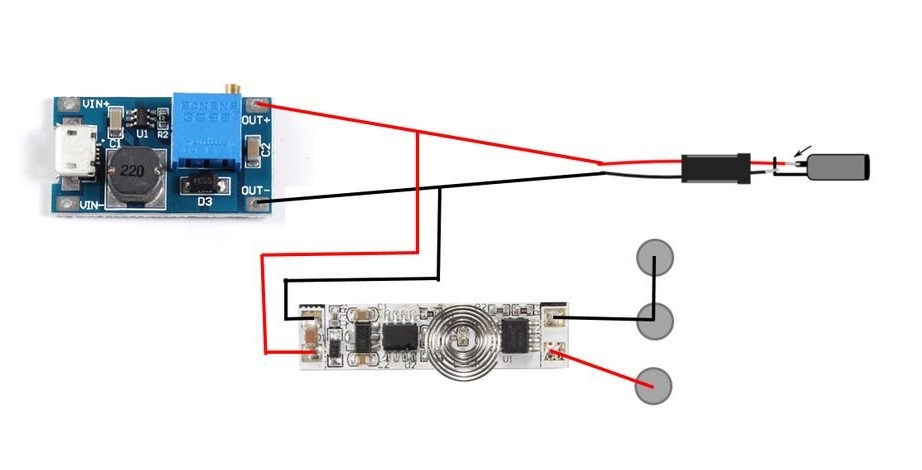
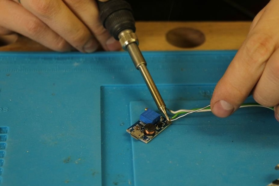
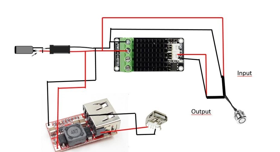
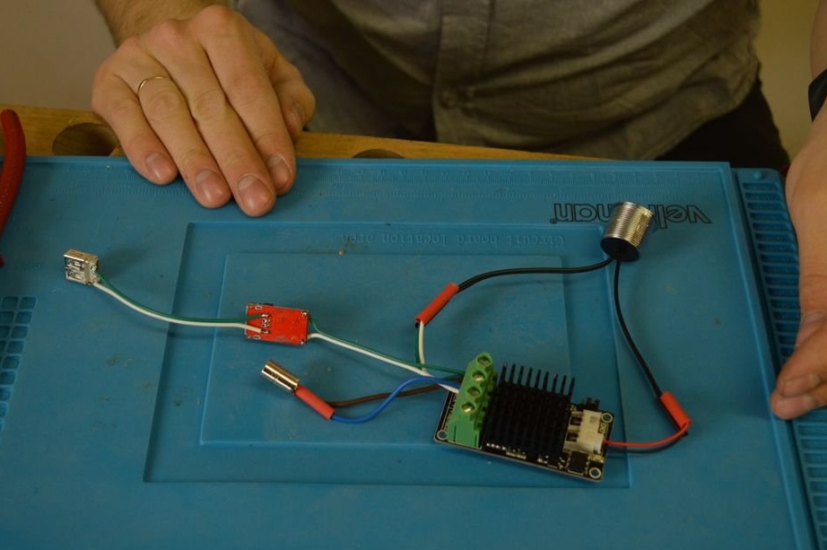
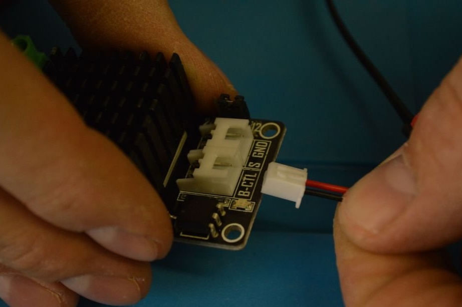
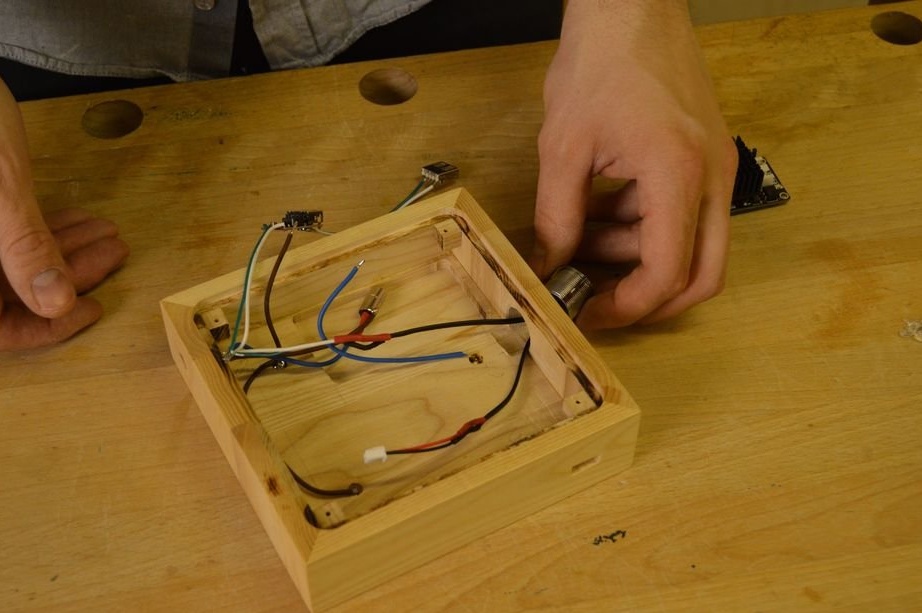
Step Twelve: electronics for a small base
According to the circuit mounts the electronic part of a small base.
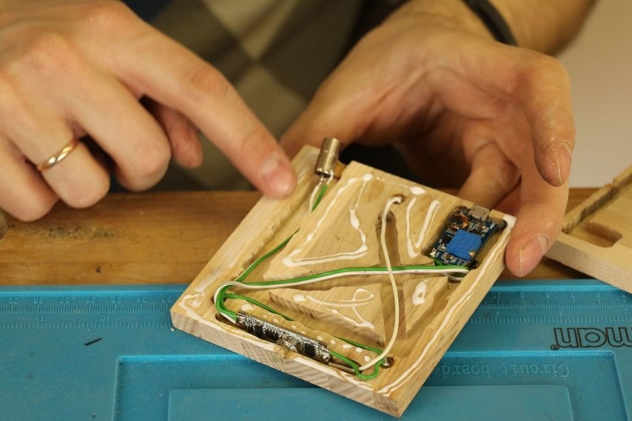
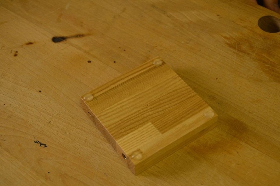
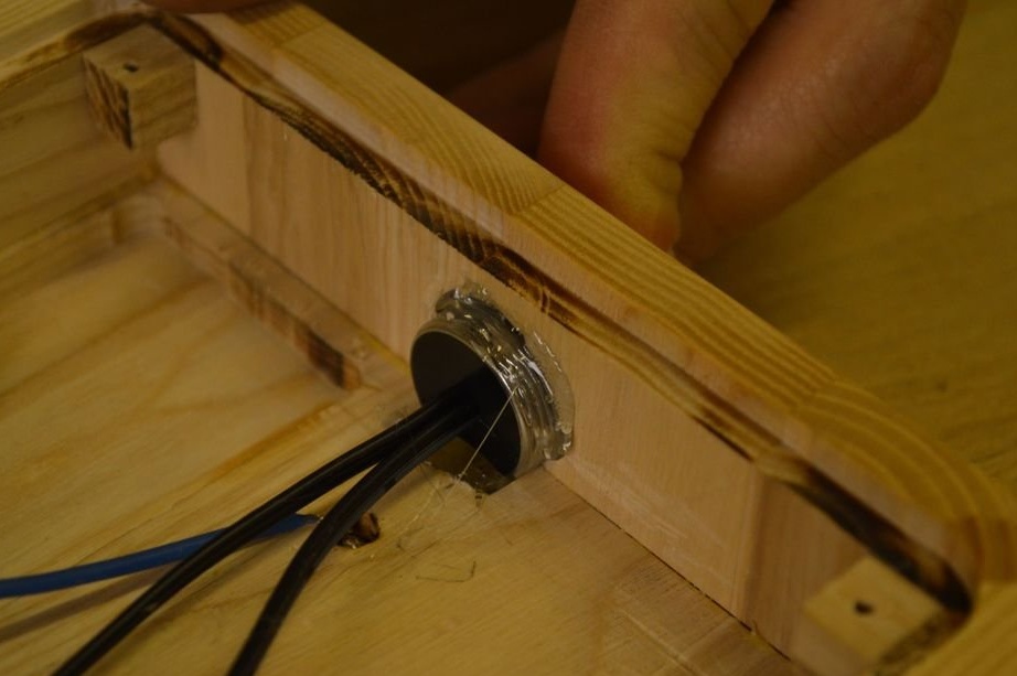
Glues both halves of the base. Then it polishes and varnishes.
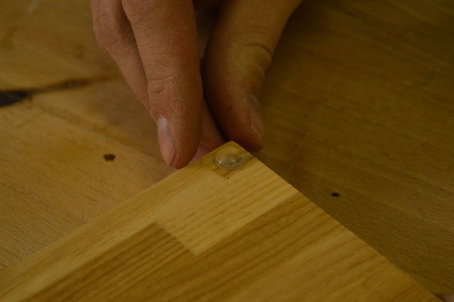
Installs magnets. Glues the legs.
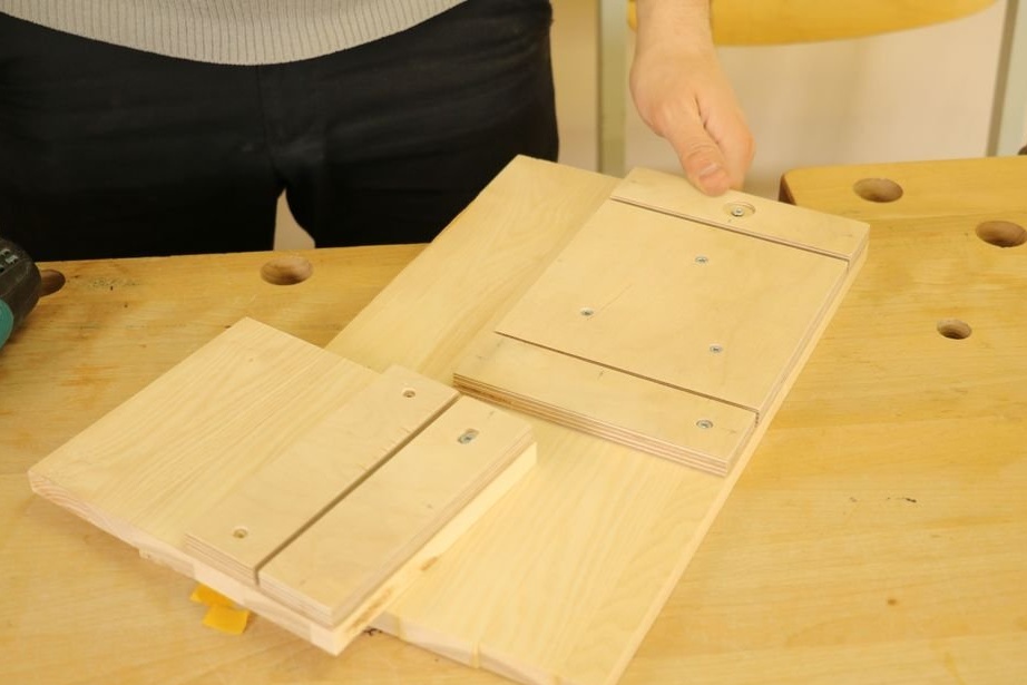
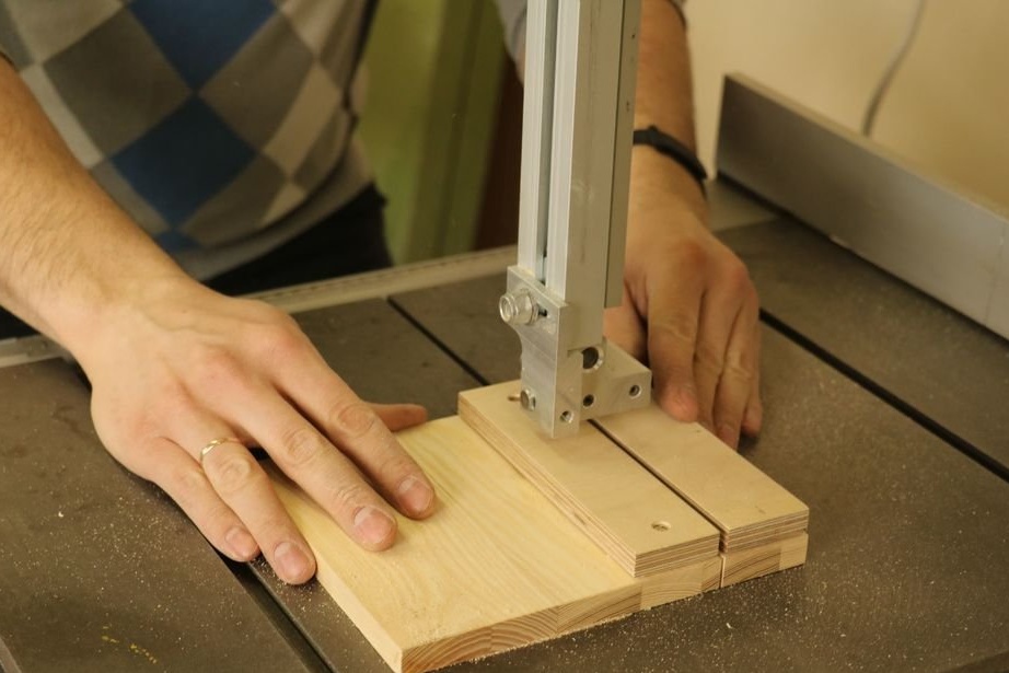
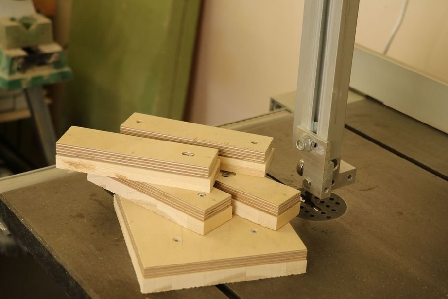
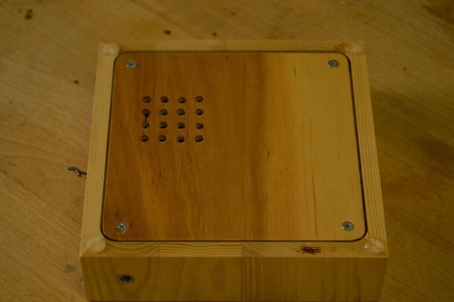
Step Thirteen: Big Base
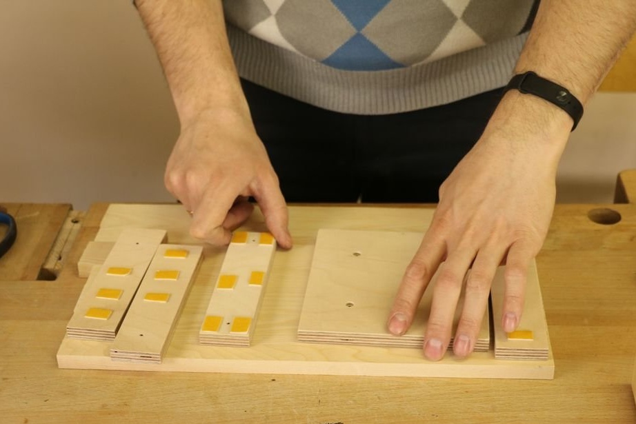
To make a large base, five blanks are needed: four -150x40 and one - 150x150.
Fixes them on one board and cuts out according to the pattern.
Big_base_v7.f3d
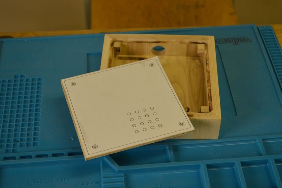
Mills a niche for electronics.
Gathers the base of the base.
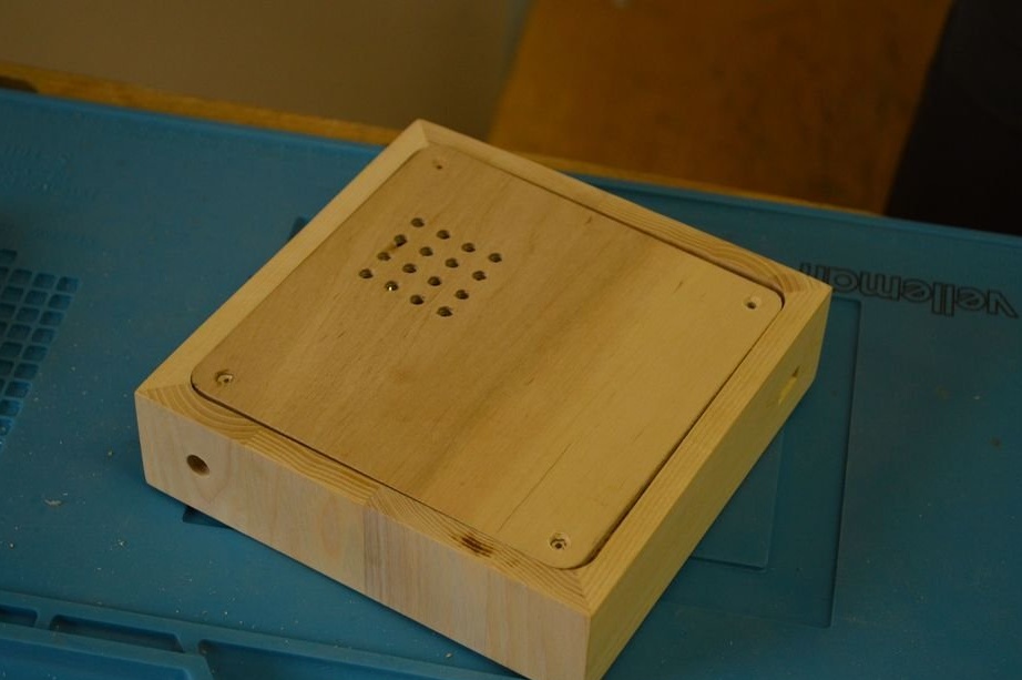
Makes a cover. Covers everything with varnish.
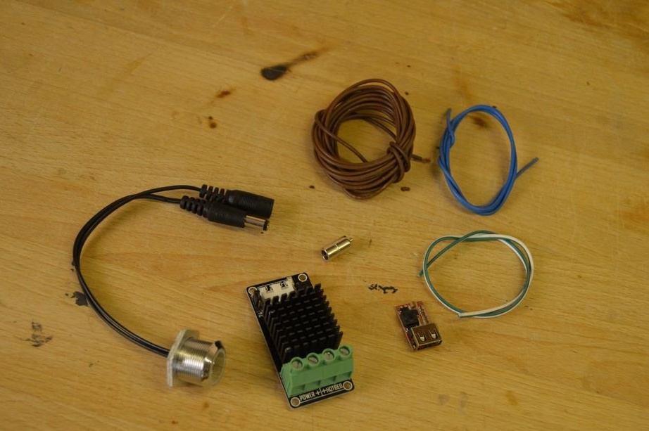
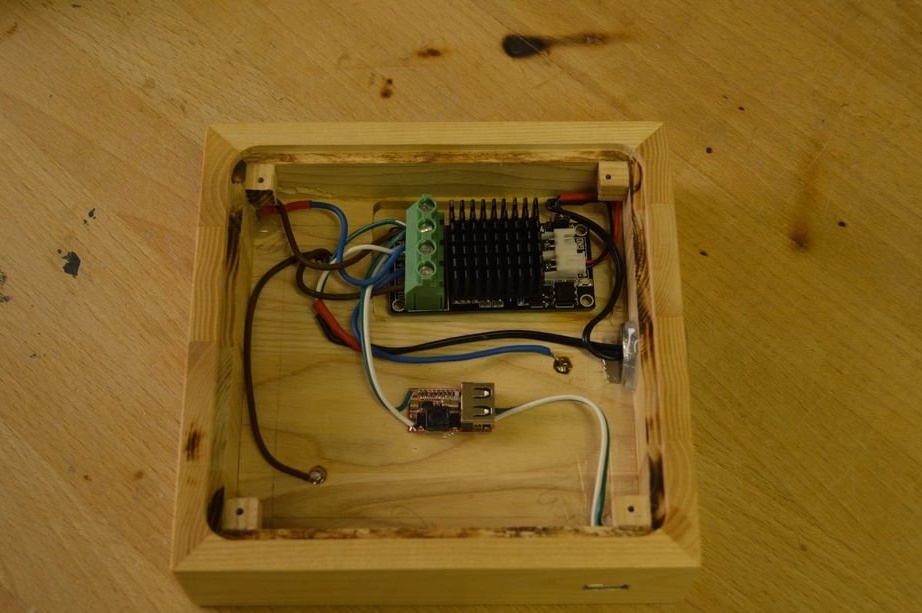
Step fourteen: electronics for a large base
According to the scheme, it installs electronics.
Installs the bottom cover and glues the legs.
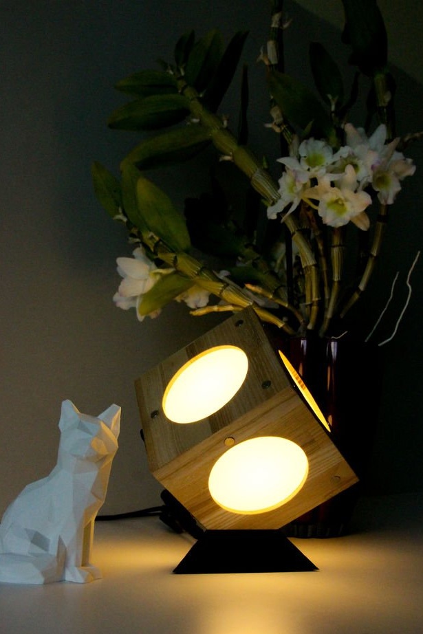
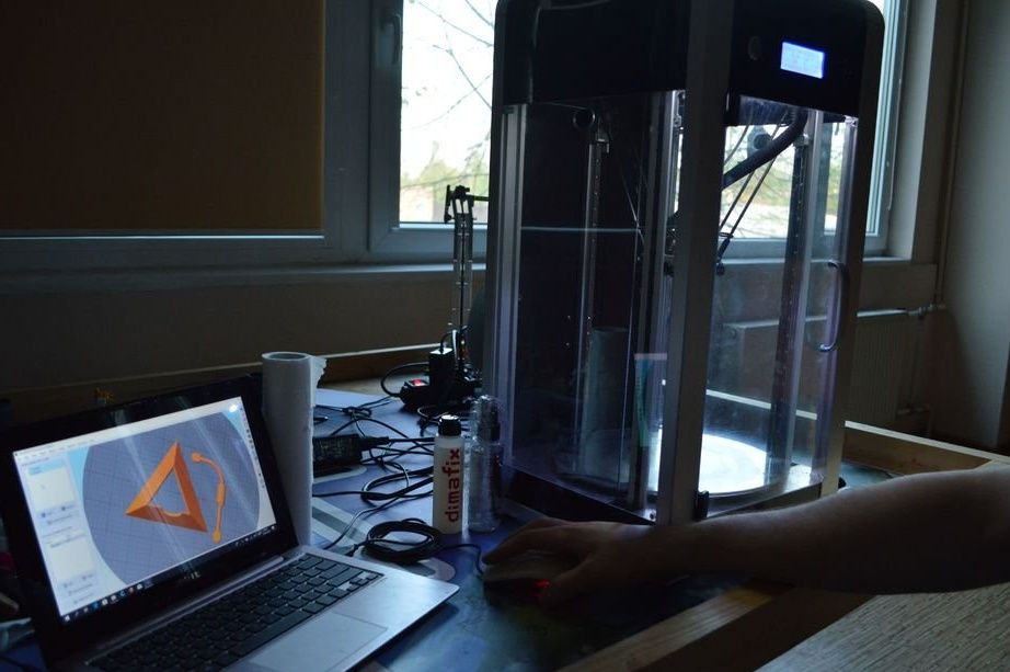
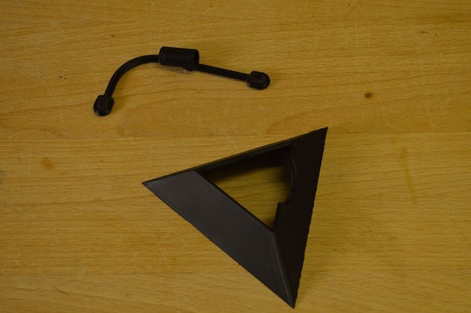
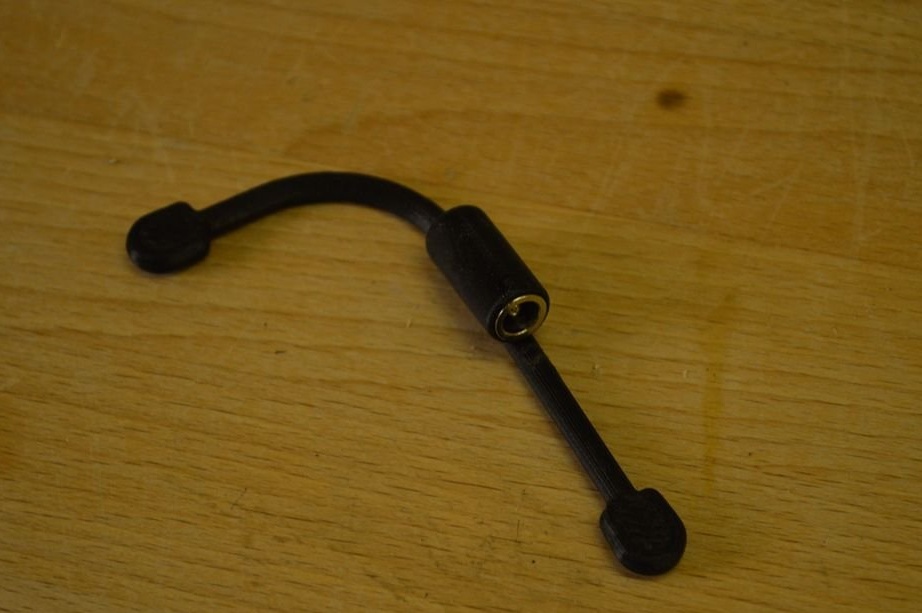
Step Fifteen: 3D Base
To install one cube at an angle, you can print the base on a 3D printer.
Files can be downloaded here and here.
From myself: a lot of material was not included in this article because of the large volume, if you decide to repeat this homemade product I advise you to read all the material on source site.