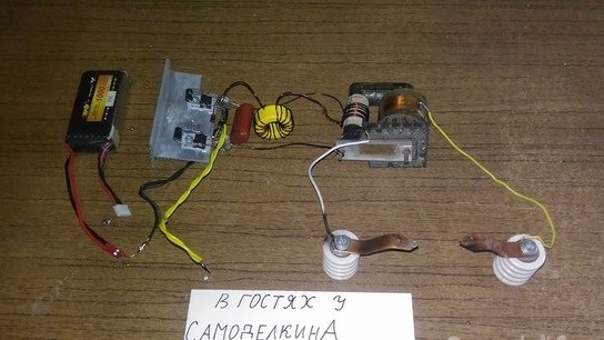
Hello, today I will show you the process of creating a very simple, and at the same time, powerful push-pull converter with a voltage of 9 kV.
The essence of the device is very simple. We apply a voltage of 12 V to the input, and at the output we obtain a voltage of about 9 kV. In this case, the efficiency of the circuit reaches 95%!
In general, the circuit itself starts working from 4V, but the output voltage will be no more than 3kV.
The scope of the device is all different. For example, they are used for Tesla coils, air ionization, in plasma lighters.
Attention! High voltage! Observe TB!
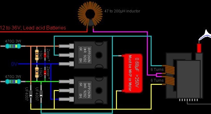
Here is the assembly diagram
Before starting, I would like to tell you as simply and briefly as possible how this scheme works.
The main thing in this circuit is 2 transistors (and therefore push-pull) and a high-voltage transformer.
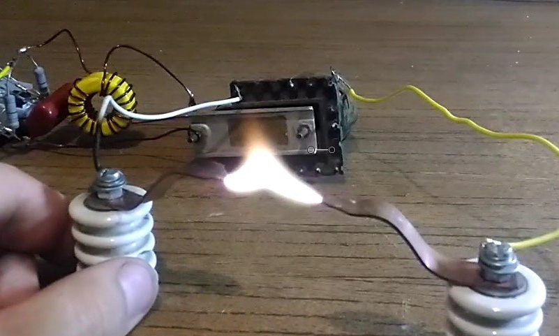
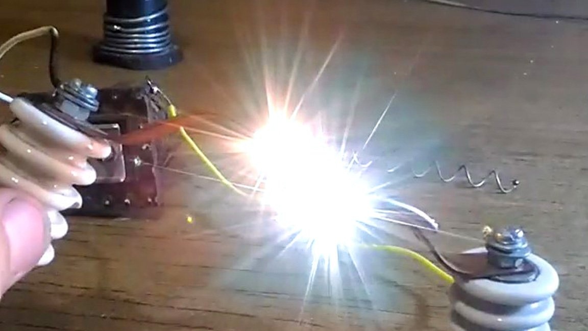
One of the transistors opens and pumps one arm of the winding, then it closes and the other opens, it also pumps the other arm of the winding and all this at a frequency of 30 kHz. At the output, we get a "bold" arc that can "stretch" up to 3 cm (when powered from 16V - 5cm)!
Before you start reading the article, I recommend that you look at the assembly and testing process:
Here's what we need:

Detailed manufacturing description:
Step 1: Winding the transformer winding. We will prepare the transformer.
Take 1mm wire2 1 meter and start winding the winding.
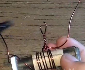
We pass the wire and just holding it, we wind 3 turns of wire.
In the next, fourth round, it is necessary to make the so-called "challenge". That is, it’s easy to thread, but not completely, to get such a ring.
This ring needs to be pressed a little.
And then twist. But de end.
Then wind the remaining 3 turns (and personally, I tied the end around this "tap" so that the coil would not spin)
That's how it should work out.
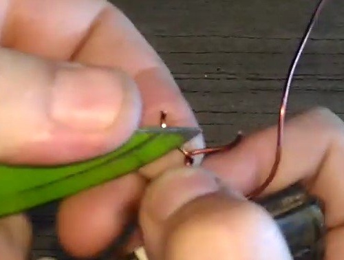
After we bite off the extra piece (it is still useful to us), the wires are side cutters.
And also a small ring with a tap.
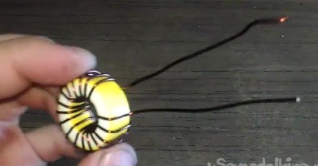
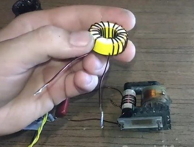
This is the final, ready-made transformer.
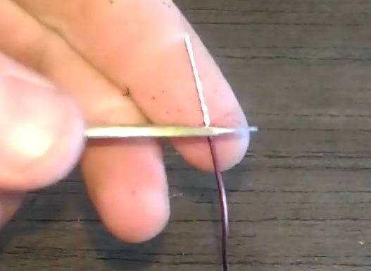
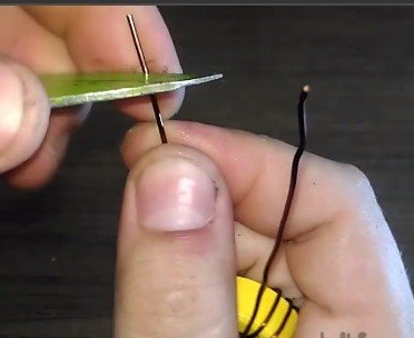
It remains only to strip the ends and tin them.
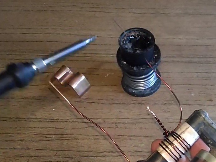
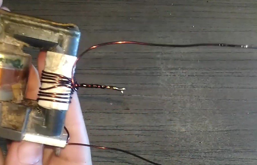
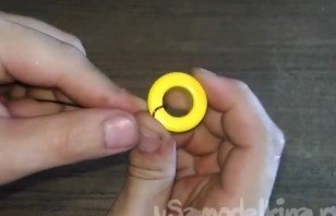
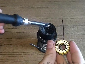
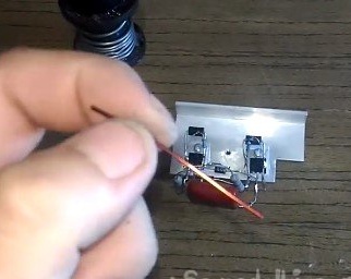
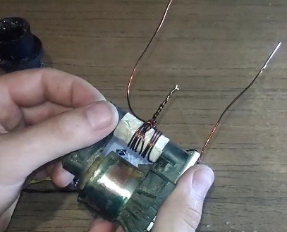
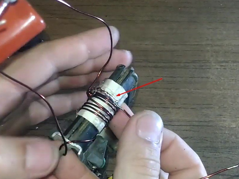
Step 2: Winding the ferrite ring. Take a ring and a piece of wire that remains after winding a trance.
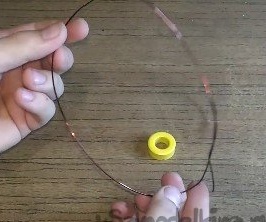
We pass the wire, holding with our finger we make about 16-18 turns.
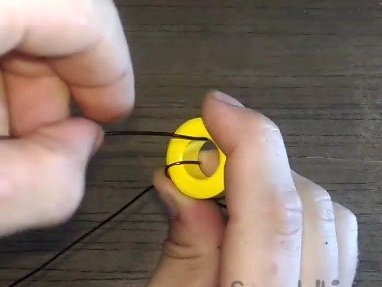

This is how it should go.
Then everything is the same, we clean the trick.
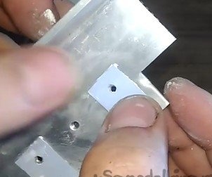
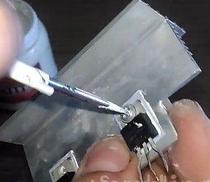
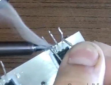
Step 3: Prepare the radiator. First we’ll sell the screws in the insulating washers.

Next, apply thermal grease to mica pads and transistors.
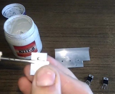
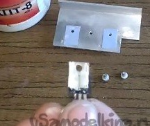
Next we lean the gaskets to the radiator
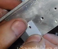
And then the transistors themselves.
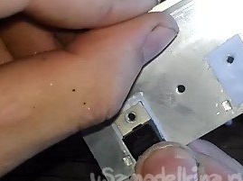
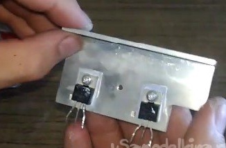
We fasten them to the radiator (I recall through the screws with insulating washers)
Total.
Step 2: Soldering.
Prepare the zener diodes.
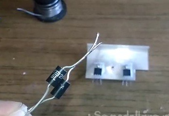
And solder them between the gate and the source of the transistor.
We do the same with the second transistor. And we get it at this step.

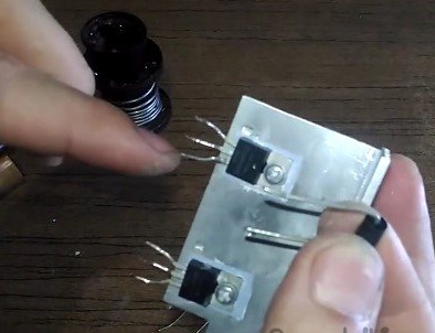
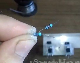
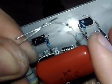
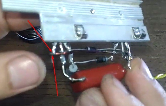
Next, solder the 10kΩ resistors as well as the zener diodes (between 1 and 3 legs of the transistor)
Then we solder the diodes. The anode of the diode ("plus") to the gate of the left transistor, and the cathode ("minus") to the drain of the right transistor.
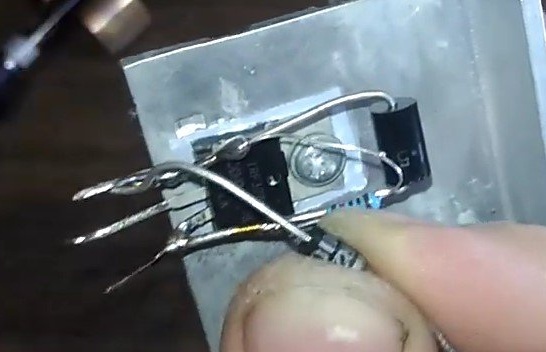
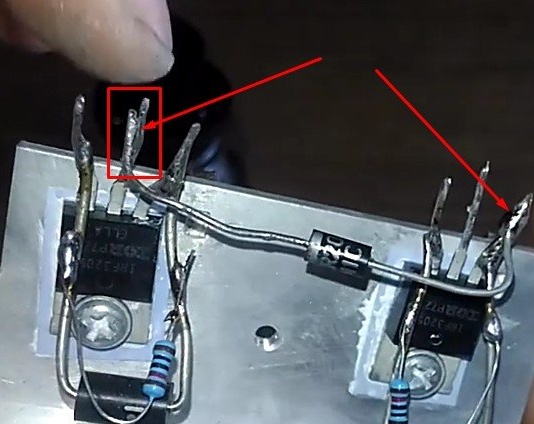
And vice versa.
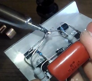
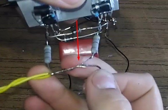
The turn of the capacitor has come.
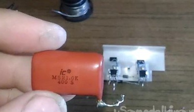
It is soldered parallel to the drains (central legs) of the transistors.
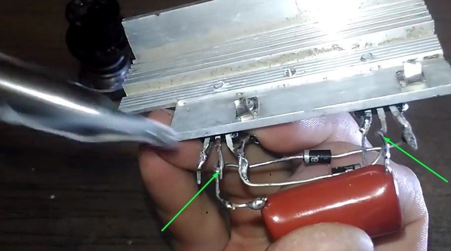
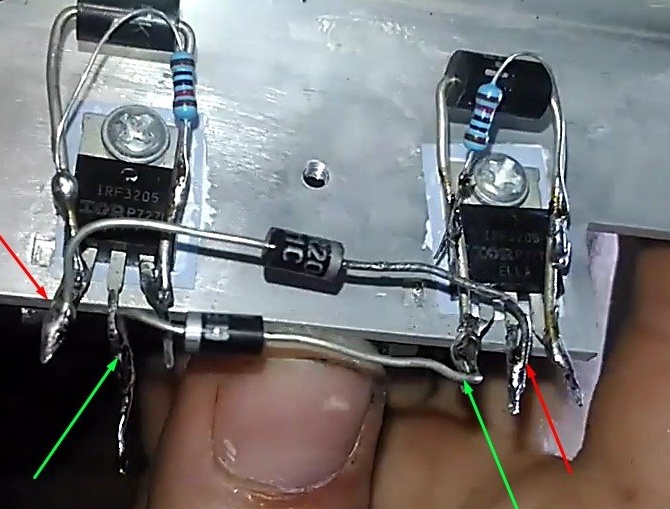
It remains to "deal with the shutters." Take our 220Ω resistors and just solder them to the gates of both transistors.
The ends of these resistors are interconnected and soldered for a more reliable contact.
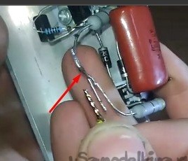
We still have a small piece of 1mm wire.
It is necessary to clean it from both ends. And make a kind of "jumper" in these areas (we connect the sources).
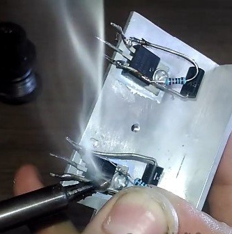
In the wake of this, solder the power wires.
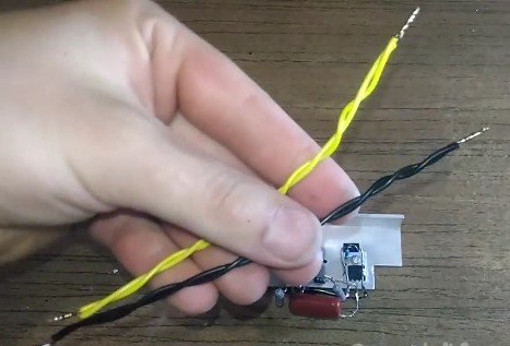
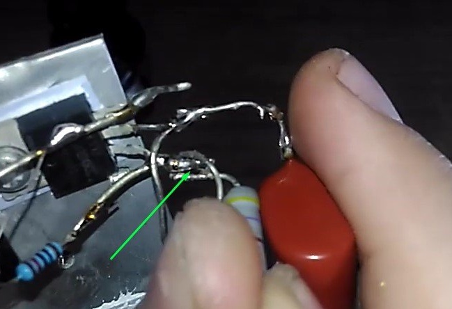
Plus the power supply (yellow wire) is soldered to the connection point of the resistors at 220 Ohms.
A black wire (minus) to the source of any of the transistors (let me remind you they are connected by a jumper)
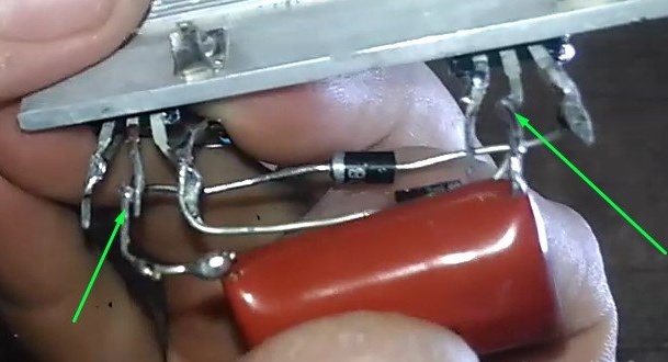
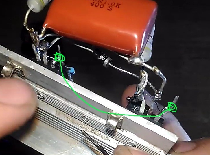
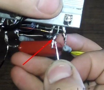
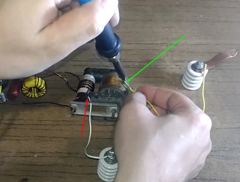
The turn of the most "main" has come.
The ends of the transformer winding are soldered parallel to the capacitor.
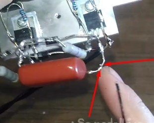
Let's make a ferrite ring.
One end of which is soldered to the tap.
And the second to the junction of 2 resistors at 220 ohms.
Now it remains only to solder the high-voltage arresters to the transformer to the high voltage output.
And that is all! It remains only to connect. On the yellow (positive) and black (negative) wires, we supply voltage from 4v.