» Topics » Advice »Dorofeev sound amplifier on SMD components

Dorofeev sound amplifier on SMD components

Greetings dear the inhabitants of our site!
I am glad to present to your attention the time-tested scheme of the audio frequency amplifier according to the Dorofeev scheme made on one operational amplifier and four transistors.

The scheme is very simple, it does not require any configuration, it starts working immediately after assembly and is even affordable for beginner hams. Despite its simplicity, the amplifier has a fairly high-quality sound and an output power of about 50 watts, which is more than enough for a living room. This circuit operates in Class B, and was first published in Radio magazine, issue No. 3 for 1991 under the heading Mode B in AF power amplifiers.


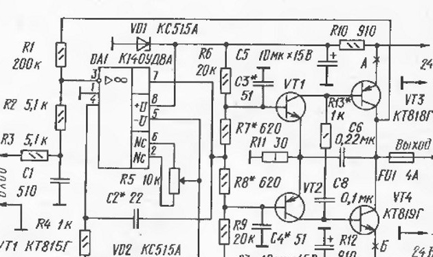
As you can see, the circuit is really very simple, but it is built on a domestic element base, which is now not so easy to find, there are many options and modifications of this amplifier on the Internet, for example, it has been converted to a modern base and slightly modernized, also a similar one was presented on this site scheme "DIY 50W Transistor Amplifier”, But unlike it, our board will mainly consist of smd components, which will allow us to mount the board entirely on a radiator and assemble a more compact amplifier based on a modern element base. To power the amplifier, you need a power supply with an output bipolar voltage of 25 volts per shoulder and a power of 100-150 watts. The circuit of our amplifier will look like this:


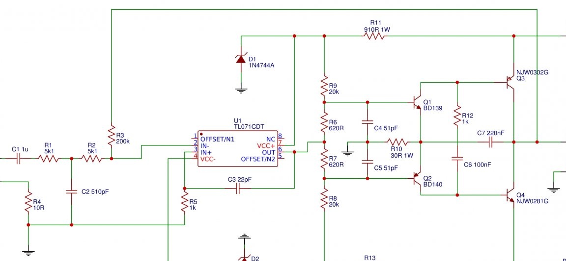
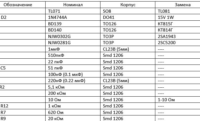
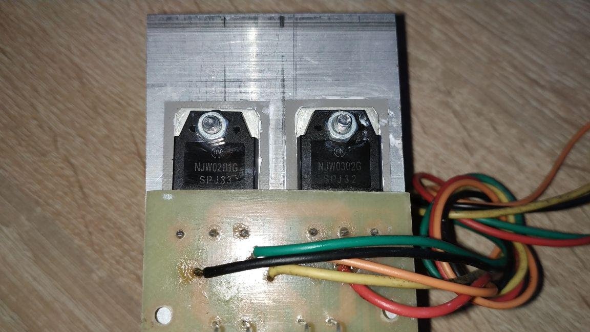
As you can see, the circuit does not contain expensive and scarce components, all of them can be bought in almost every radio store, or radio market. The operational amplifier in our version will be TL071 (you can put TL081) in the SO8 package, pre-output transistors are a common complementary pair of BD139 / BD140, NJW0302 / NJW0281 will be used as output transistors (you can put a “people's” pair 2SC5200 / 2SA194344), the zener diode replace by any one with a stabilization voltage of 15 volts and a dissipation power of at least 1 Watt. With this circuitry and a supply voltage of +/- 25 volts (bipolar), you can remove about 50 watts per load of 4 Ohms.You can raise the supply voltage to 30-36 volts per lecho and remove at the same time more than 100 watts per channel, but for this you need to replace two one-watt resistors with a nominal value of 910 Ohms with the same power, with a nominal value of 2 kilo ohms, all smd components are made in a 1206 case, output capacitors - film.
For assembly we need:

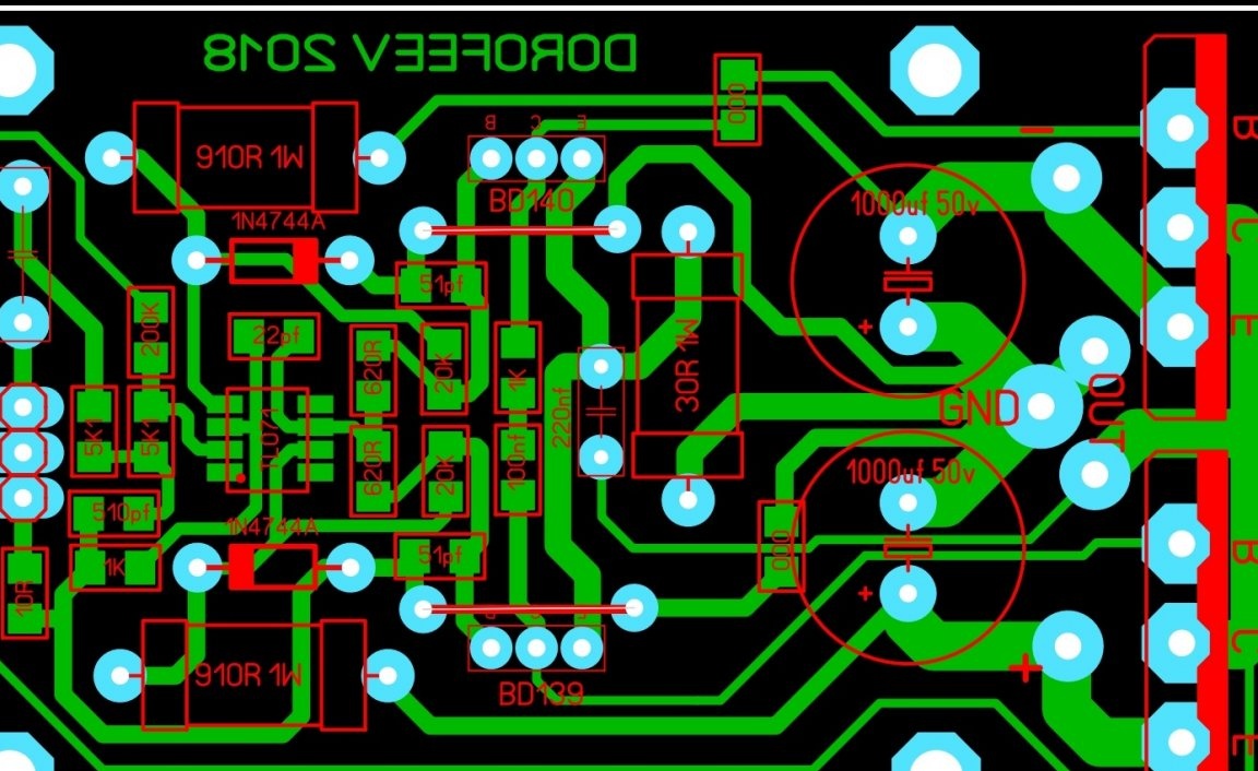
First we need to make a fee. I do it using the method Laser Ironing Technology (LUT), the layout of my authorship board looks like this (download the board in lay format):

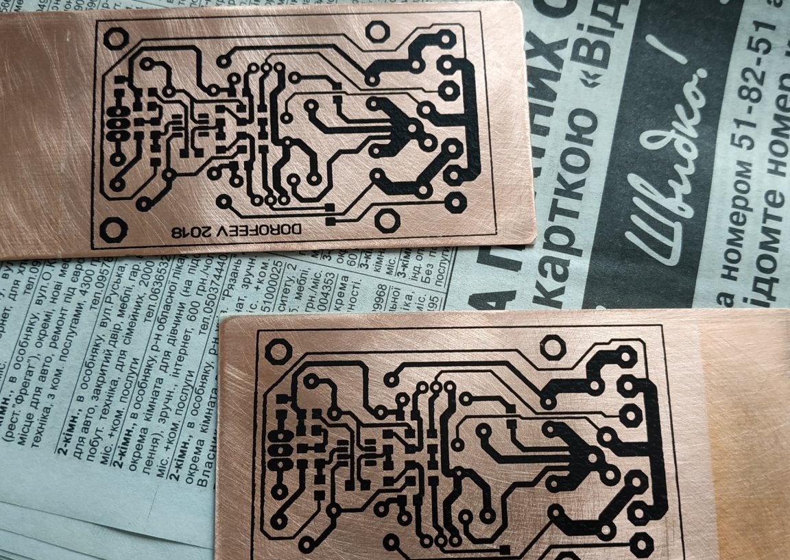
We print the board pattern onto the thermal transfer paper and transfer it to fiberglass using a conventional iron:

Then we poison it in ferric chloride (or in a solution of hydrogen peroxide, salt and citric acid), drill holes and poke tracks (I personally puddle in the Rose alloy in boiling water with citric acid added), and we get such beauty:

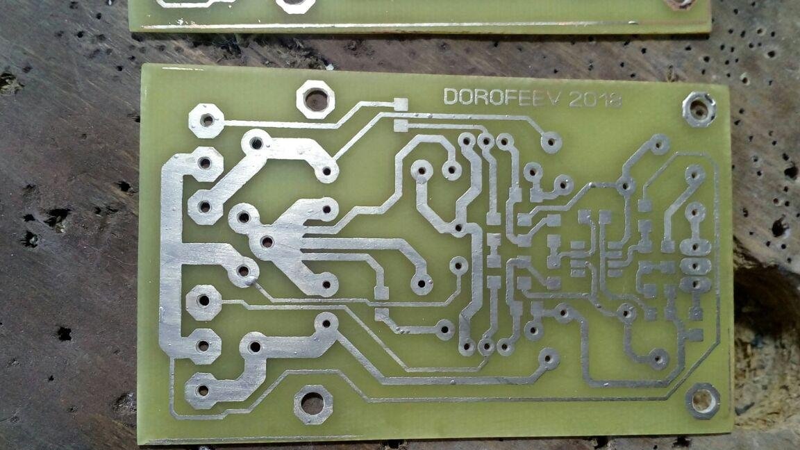
As for me, the board is not badly divorced, because when the amplifier is working, there is absolutely no background and interference
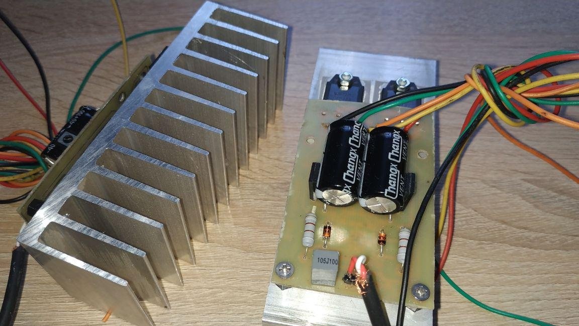
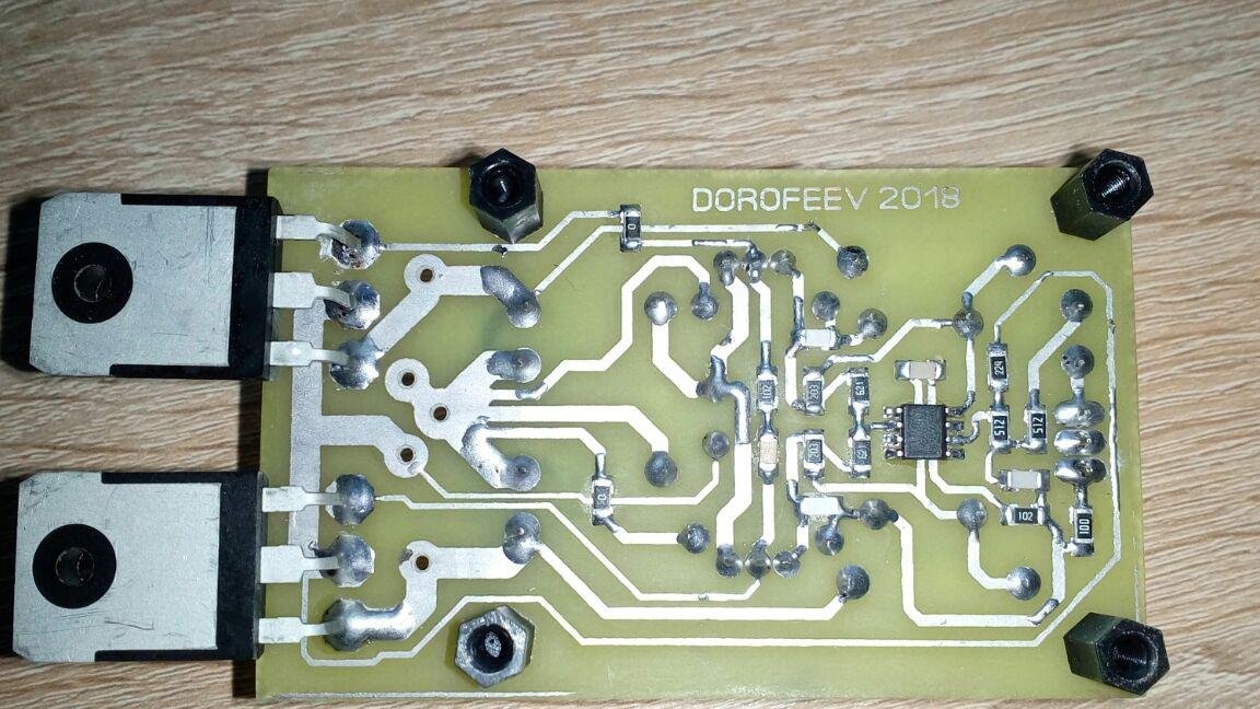
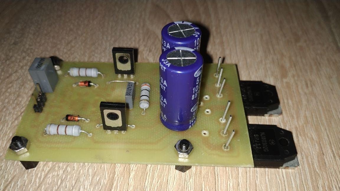
Next, we solder the smd components first, and then all the output ones, from smaller to large for ease of soldering. After soldering the washing flux we get the following result:

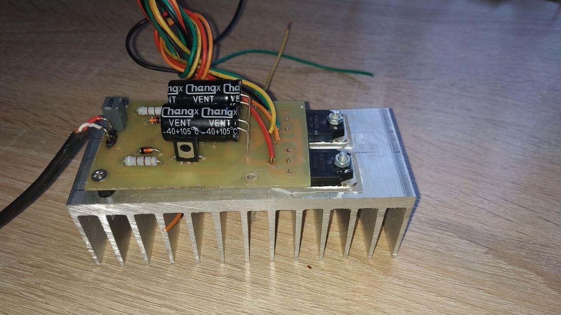
After that, you can try turning on the amplifier to check the operability, since the output transistors are not yet installed on the radiator, you need to turn on the device for no more than one minute and apply a low volume music signal to the input, or simply touch the input with your finger. If everything is assembled correctly, then the amplifier will immediately start working and music should play in the dynamics, or the background from your fingers, if this is not the case, you need to make sure that all components are installed correctly, and in the absence of random jumpers between tracks from solder droplets, you should also pay attention on the correct installation of zener diodes, and transistors, and also the correct polarity of electrolytic capacitors. Next, you need to install the board on the radiators, first we mark the places for the holes, punch and drill with a 2.5 mm drill, then we drop a couple of drops of engine oil into each hole and use the M3 tap to screw the thread. There is enough excess radiator data, and even at maximum power, the radiators do not heat up much (no more than 35-40 degrees)


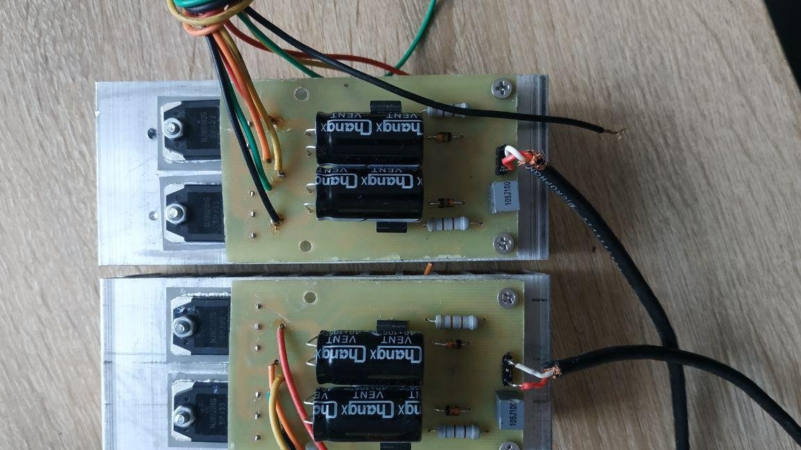
The output transistors must be isolated from the radiator using insulating gaskets with thermal paste:

After assembly, you can proceed to full testing and listening. The circuit showed a good result, good sound, and reliability.

Enjoy your homemade!

Suitable for topic

Related topics

Add a comment

    • smilesmilesxaxaokdontknowyahoonea
      bossscratchfoolyesyes-yesaggressivesecret
      sorrydancedance2dance3pardonhelpdrinks
      stopfriendsgoodgoodgoodwhistleswoontongue
      smokeclappingcraydeclarederisivedon-t_mentiondownload
      heatirefullaugh1mdameetingmoskingnegative
      not_ipopcornpunishreadscarescaressearch
      tauntthank_youthisto_clueumnikacuteagree
      badbeeeblack_eyeblum3blushboastboredom
      censoredpleasantrysecret2threatenvictoryyusun_bespectacled
      shokrespektlolprevedwelcomekrutoyya_za
      ya_dobryihelperne_huliganne_othodifludbanclose
33 commentary
Guest Alex
and by the way, I set the weekend to TIP 35-36С and the mode reached the class AB, it doesn’t get warm, I had to put an impressive radiator.
Guest Alex
in my opinion the size turned out even more, I collected it still shakes in the garage, the scarves 6.5x6 cm in size turned out, class!
Melkov Sergey Nikolaevich
A good article, everything is correctly shown and painted. (Even a schoolboy will collect) (-:) _)). The author is well done!
Guest Serge
He collected it very carefully and classically. I won’t talk about sound. Amp of my youth ...
Why so expensive here? Cheap op-amp, 4 low-cost transistors, two dozen simple muffins. Everything else - the case, PSU, radiator - are the same as with the IP you specified. Only for the IC radiator with the same output power need more.
Guest Sergey
Sane people, categories of perverts ... This is Satanism!
So much emotion about anything, argumentation with claims to an absolute monopoly on the truth! nea
Guest Sergey
Don't you think that you are 25 years behind? What is tube sound about? Sane people have long identified a niche of lamps - guitar comics))) The rest of the people who prefer to listen to music with distortions (no matter which) can still be classified as perverts. The current even super-expensive amplifiers are made on transistors) I just repaired the Parasound HALO-JC1. A single-channel powerhouse at a price of about 500 tr So he is not a fig on lamps))) This is also a kind of perversion for me, as an engineer, but at least ...) There are many ways to raise people into grandmothers ... But not lamps !!! This is Satanism!)))
Author
At a local Ukrainian aluminum products store
Author
Then why collect anything at all, if you can buy a ready-made amplifier in the case?
Guest Sergey
Did it ever occur to you that m / s type LM3886 or TDA7293 is several times cooler than this garbage? And cheaper at times))) How much more can you give birth to a bicycle when it has long been sold in a store?
Guest Alexander
Hello!
Where did you buy such a radiator?
Guest Alex
Andryukha. offer your little scheme
Evgeny Alexandrovich
TTX did not delve into the intricacies, but to the author from me - GREAT GRATITUDE! He returned me to my student amateur radio youth!
Guest Nikolaj
To your remark about tube amplifiers - do not forget
And let's not forget about the difference between the "electron - hole" conductivity in semiconductors and electrons in vacuum tubes!
it turns out the so-called "tube sound"
You turned everything upside down, in fact, we are criticizing precisely the "transistor, integrated, semiconductor sound", and with the "tube sound" everything is OK! ok
Guest Nikolaj
To your remark about tube amplifiers - do not forget that matching transformers are used there, so they remove intermodulation distortions due to their inductance, and the so-called "Lamp Sound" is obtained.
Guest Alexander
all amplifiers sound the same
And what is your opinion on the sound of tube amplifiers with a THD of 2-3%?
I'm not talking about amplifiers for 0.005 and 0.0004
And what, in your opinion, should the SOI have for sound carriers and preamps? I won’t ask about acoustics! scratch
Guest Alexander
In parallel, the zener diodes need to put capacities of 100 microfarads and 01 microfarads. The amplifier will work more stable and the harmonic distortion will decrease. According to the article. What drives science. Earplug approach
measurements are purely emotional and nothing more. Notice darling, our quality of amplifiers has improved over the years - thanks to measurements of the main electrical parameters of amplifiers. Behind a harmonic coefficient of 0.01 if the power supply, the excellent sound of all amplifiers is the same. I'm not talking about amplifiers for 0.005 and 0.0004
74
I DO NOT KNOW BUT THE COOL CRAFT
For starters, you would figure out how this amplifier works before making such statements. What specific parameters will change when the signal at the input of the ultrasonic scanner changes?
Guest Alex
The complete absence of thermal stabilization of the output stage is a guarantee
self-heating or step type distortion.
The author believes that it is necessary. Now I thought and realized that he had KT814-819, and your β is higher, then you really are right. But if they do not heat up, then the output radiators are too large. However, you yourself noted the excess area of ​​the radiators.
The power allocated at the output, roughly, to a first approximation, for such a circuit is 2 • β times less than the power allocated at the output transistors (β - β output transistors).The efficiency of the output stage is approximately 75%, which means that at an output power of 50 W, at least 12.5 W will be dissipated on the output pair, with a margin of 15 W. β of a weekend of at least 75. Indeed, a miserable 50 mW will be dissipated at the weekend, radiators are not needed.
Author
I agree, the scheme is not ideal, but just do not write it off. For beginner hams, the very thing is to practice and gain experience. Moreover, it sounds hehe worse than the average TDA
Author
Why do they need radiators? They do not bask at all.
Author
What exactly is outdated? If you are a big pro and your amateur radio hobby you started right away with assembling amplifiers like Natalie, or something more complicated, then congratulations. It will be interesting for many beginner radio amateurs to assemble such a scheme without commissioning, and to believe in themselves, and continue to collect further something more complicated and much better. And do not start collecting a complex project and then abandon it and amateur radio in general.
Author
On this radiator, the transistors are practically not heated. Class B yet
Guest Igor
I didn’t make such radiators therefore aluminum plates for which the amp was called a hang glider rocked the player the cassette dances were notable and we are young
2 Dmitry Novoseletsky: pre-output transistors need small heatsinks.
About adjustment and circuit design features author (M. Dorofeev) writes here.
Guest Andrey
The mediocre scheme. No control of the through current of the output transistors. The output stage works in pure class-B, there are no base charge resorption circuits (resistors BE), 100% OOS from the output to the input with a slow op-amp as a voltage amplifier. This makes no sense!
All this is understandable. Auricular metering. Excellent sound. And where are the electrical parameters giving the main evaluation of the amplifier characteristics
I agree only in part. We appreciate the sound, all the same with our ears, and not with the waveforms, we had to deal with situations when the amplifier, ideal in instrumental measurements, sounded even worse than the average (in measurements) amplifier! smile
Why is this pointless? Successful design, easy to repeat. Not Hi-End, but reviews are good. And what would you recommend such a modern, not outdated?
Tube schemes are "outdated" even more, because they are still successfully used.
1. Unsuccessfully located transistors: on the edge of the radiator.
2. If you isolate not transistors from the radiator, but radiators from the case, then you can realize one of the advantages of the applied circuitry.
Guest Ivan
It makes no sense to do something that is long outdated. Can we collect the detector receiver?
Guest alexander
The Dorofeev amplifier is one of the excellent amplifiers. I’ll ask the author a question. You transferred the amplifier to new components. All this is understandable. Ear measurement. Excellent sound. But where are the electrics?
parameters giving the main assessment of the characteristics of the amplifier. Or so my friend from the lantern
Dorofeev clearly indicates the main parameters of the amplifier. The output stage is assembled in a symmetrical manner, plus there is a strong isolation of the terminal transistors for power in the shoulders. Yes, and stabilized. Hence the low harmonic coefficient.

We advise you to read:

Hand it for the smartphone ...