

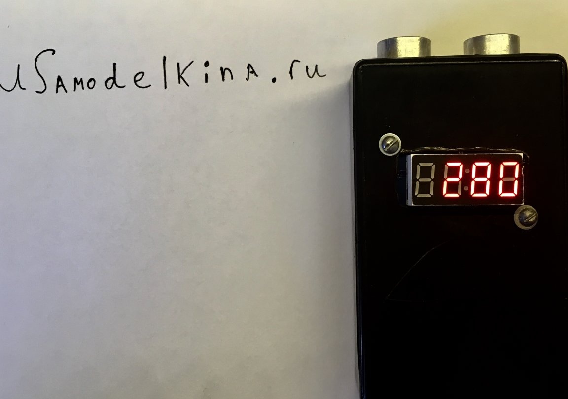
Good afternoon lovers homemade! Today we will assemble a simple rangefinder on Arduino Pro Mini. The device is capable of measuring a distance from 2 to 400 cm. The error of this device comes to just +/- 1-5 cm, depending on the measured distance.
Tools and materials
-Arduino Pro mini
Sensor HC-04
- Indicator on tm1637
-Wire (I have - MGTF 0.12)
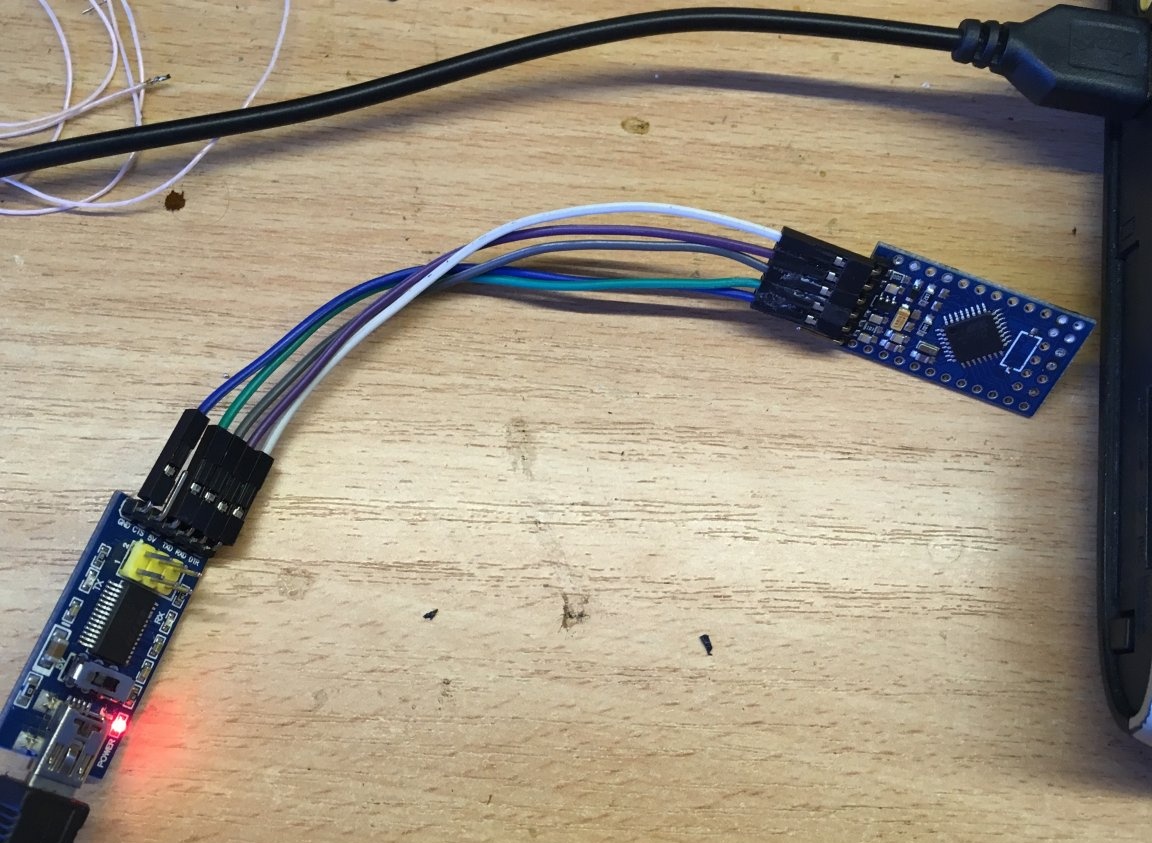
-Programmer
-Plastic housing
-Li-on battery
-Small switch
- Charging board on TP4056
-Super glue
-Soldering iron
-Solder
-Rosin
Drill, drill, etc.
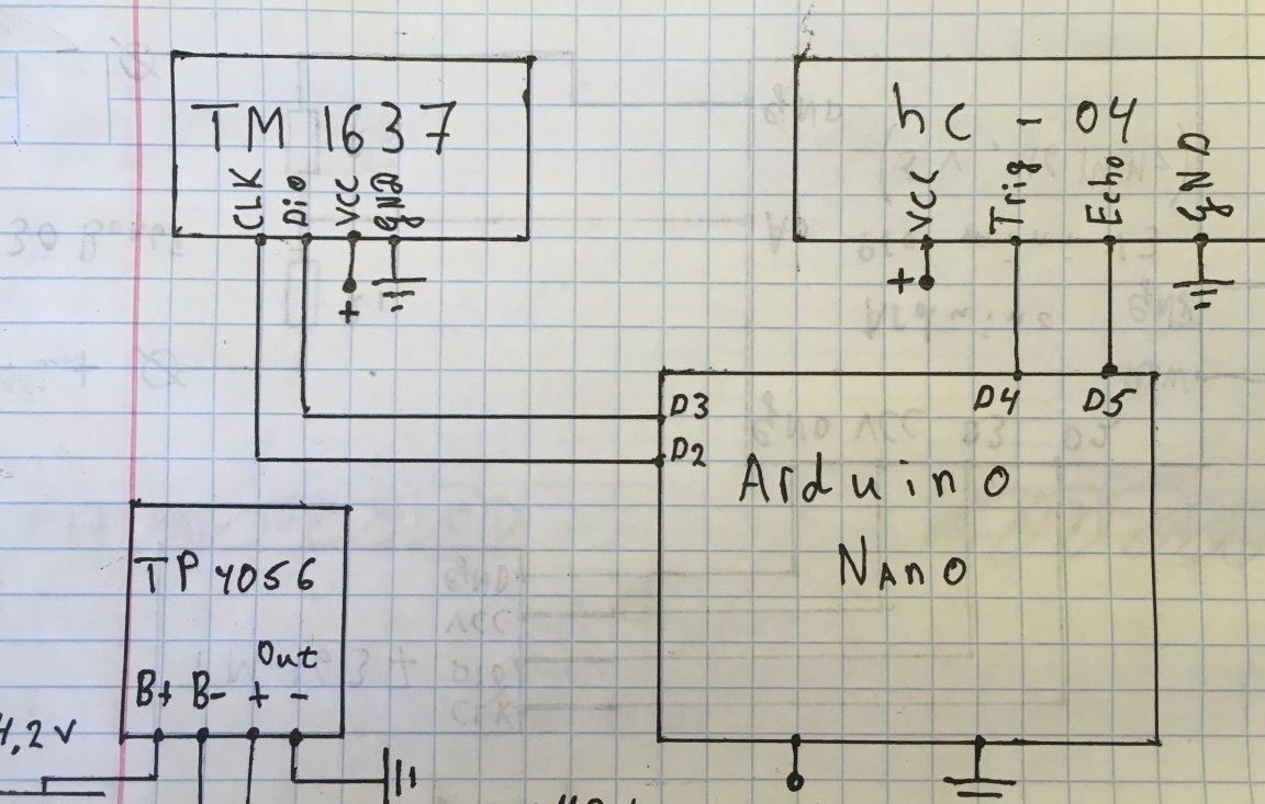
Step one. Scheme:
According to the scheme, everything is simple, without additions.
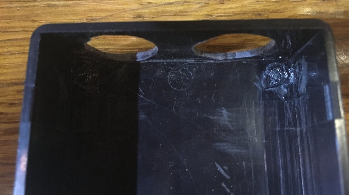
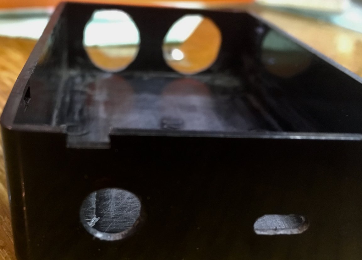
Step Two. Case Preparation:
First we try on the sensor and drill two holes for 15 mm.
Next, make a hole for a micro-usb connector with a 3-3.5 mm drill.
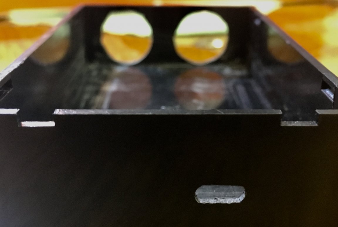
We select a drill for the diameter of the switch and drill.
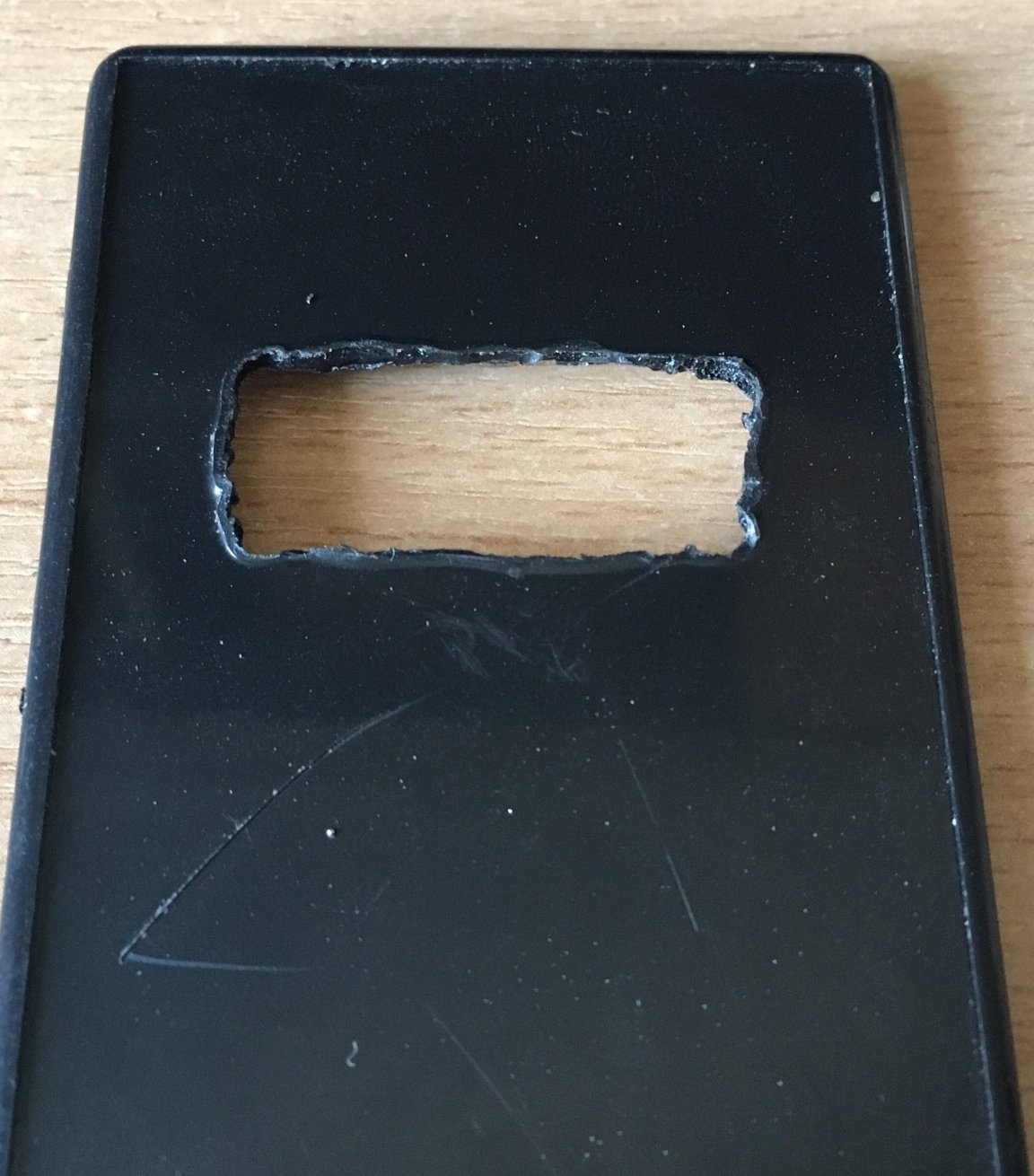
On the lid we make a “window” for the seven-segment indicator (in the photo without processing), and we finish all the irregularities with a file.
Step Three. Firmware:
In the sketch, variables that can be adjusted for yourself are highlighted. All code is commented out.
#include  // libraries for work
#include
//-------------For settings--------------------------------- --------------------------------
bool Long = 0; // 0 - measure the length from the sensor
               // 1 - measure the length from the housing wall, which is opposite to the sensor
unsigned int corpus = 10; // distance from the sensor to the opposite case wall (in centimeters)

#define CLK 2 // pins to connect
#define DIO 3
#define TRIG 4
#define ECHO 5
// ------------------------------------------------ ----------------------------------------------
unsigned int impulse = 0; // variables for calculation
unsigned int sm = 0;

GyverTM1637 disp (CLK, DIO);
void setup () {
 pinMode (TRIG, OUTPUT); // set as an output
 pinMode (ECHO, INPUT); // set as input
 disp.brightness (7); // brightness 0-7
 disp.point (0); // turn off the colon
  disp.clear (); // clear the indicator
}

void loop () {
 digitalWrite (TRIG, HIGH); // supply 5 volts
  delayMicroseconds (10); // delay 10 microseconds
  digitalWrite (TRIG, LOW); // serve 0

  impulse = pulseIn (ECHO, HIGH); // measure the pulse length
  sm = impulse / 58; // convert to centimeters

  if (Long == 1) {// check settings
    sm = sm + corpus;
  }

  if (sm <= 2) {// zero false values
    sm = 1;
  }
  if (sm> = 405) {
    sm = 1;
  }

  int integer = sm / 10;
  int decimal = sm% 10;
  decimal = decimal * 10;
 disp.displayClock (integer, decimal); // output to indicator

  delay (300); // delay 0.3 sec. between value output
}
Next, connect the programmer and flash MK.
Step Four. Assembly:
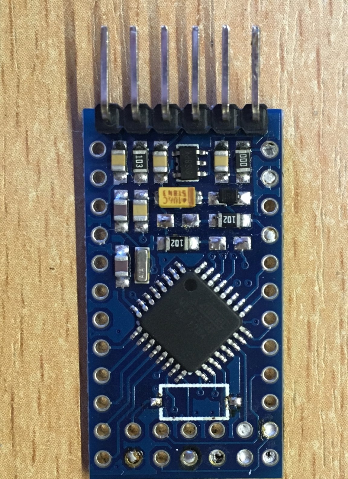
Since the device runs on battery power, we do not need extra charge. Therefore, on the Arduino board, we solder the LEDs and the reset button (to reduce the size).
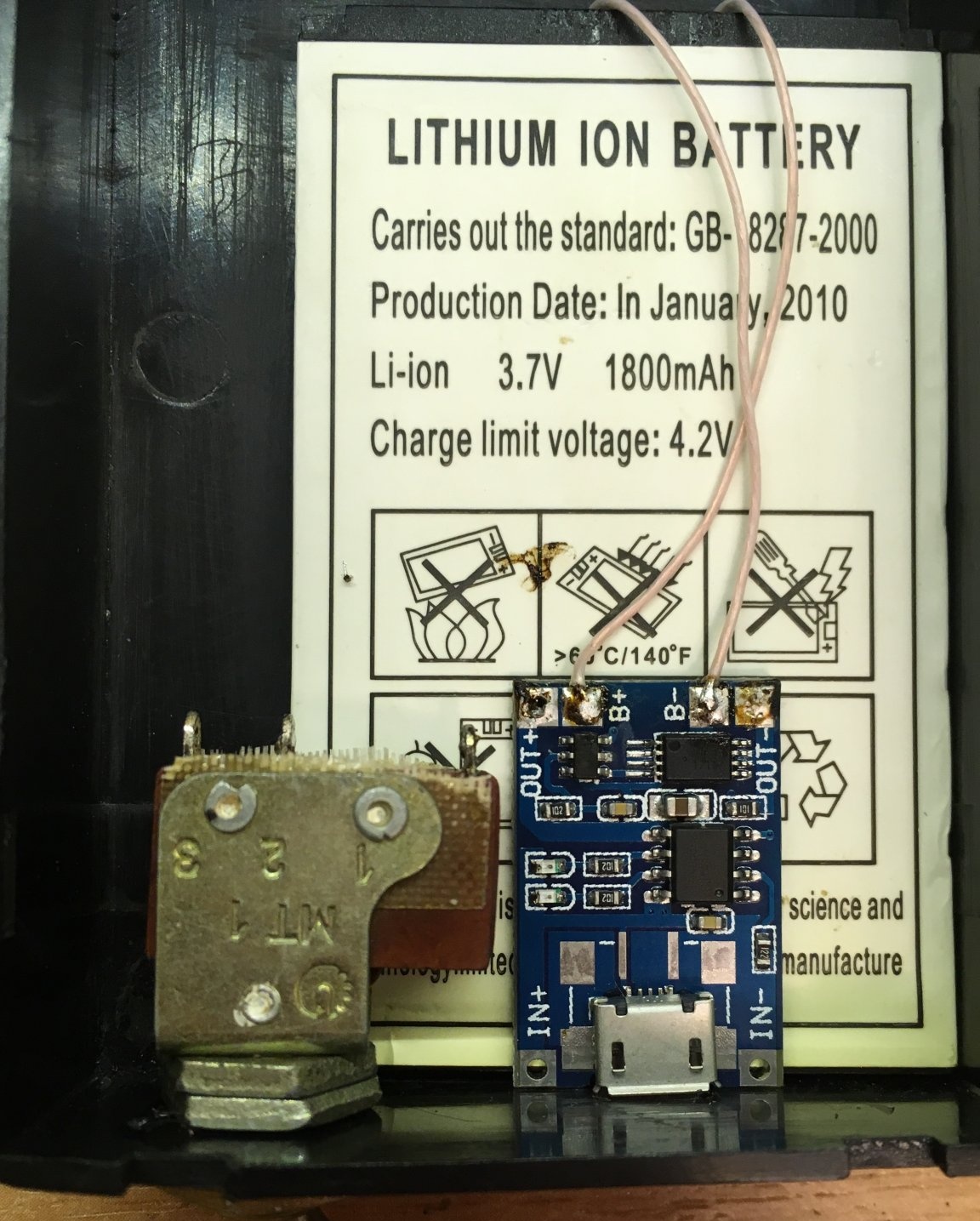
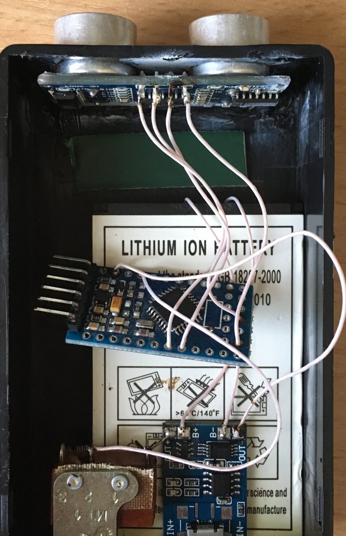
Glue the battery to the body on superglue. We glue the charging board on the battery, install the switch and solder everything according to the scheme.
We glue the sensor to the case and solder everything according to the scheme. At first there was an idea to stick the board on double-sided tape, but then it was decided to stick it on superglue. The indicator can be screwed on or glued.
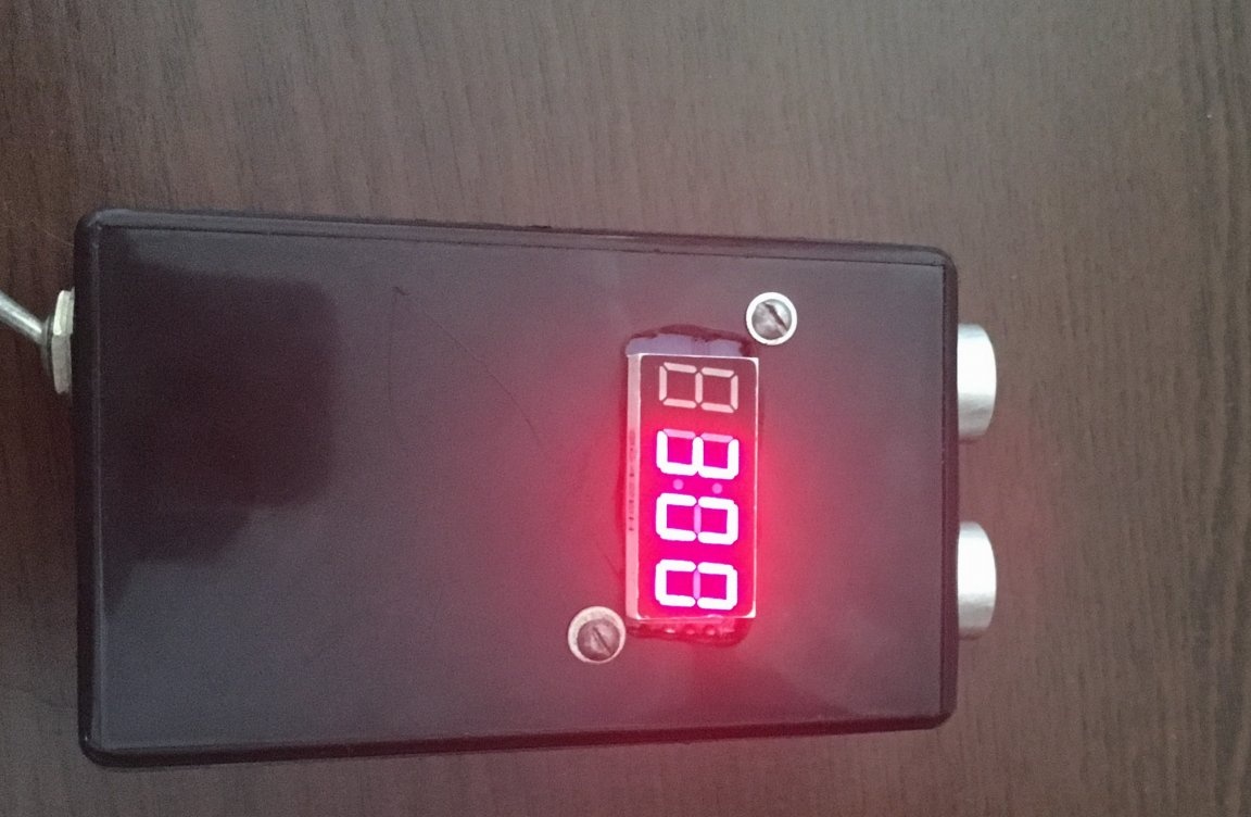
Step Five. Test:
Note: the fourth segment will always display 0. This is to ensure that the last segment is not empty. It turns out if the reading is 270, then this means that the distance is 27 cm.
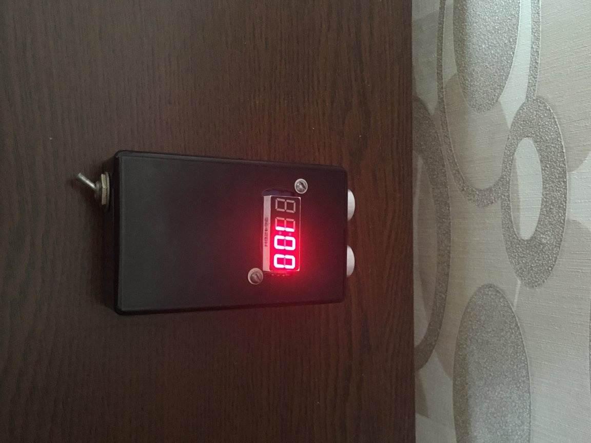
To be sure, the testimony can be verified with the ruler.