» Electronics »Current controller for welding machine

Welding machine current regulator


Greetings the inhabitants of our site!
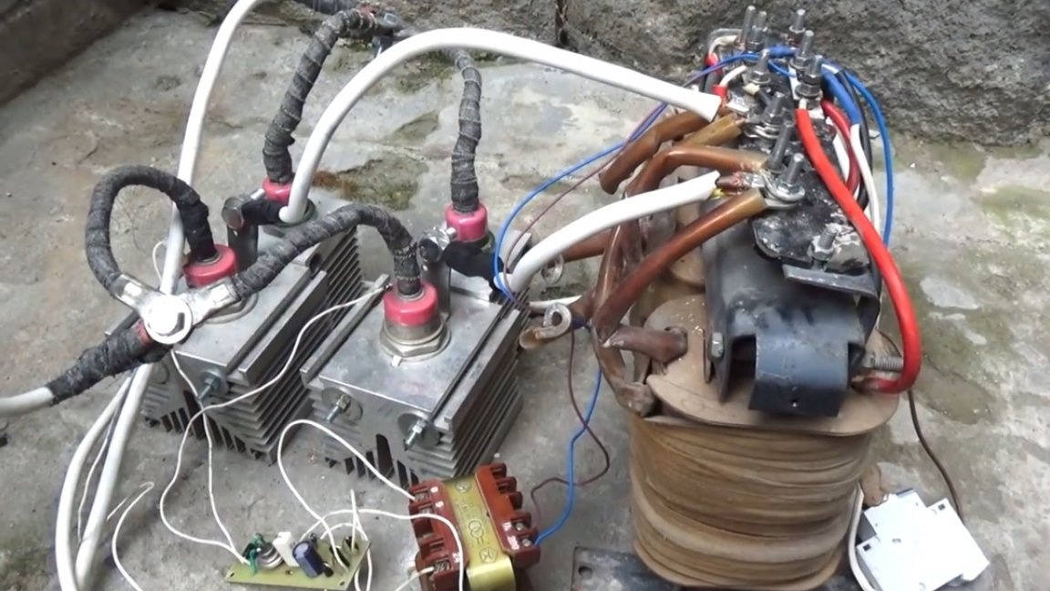
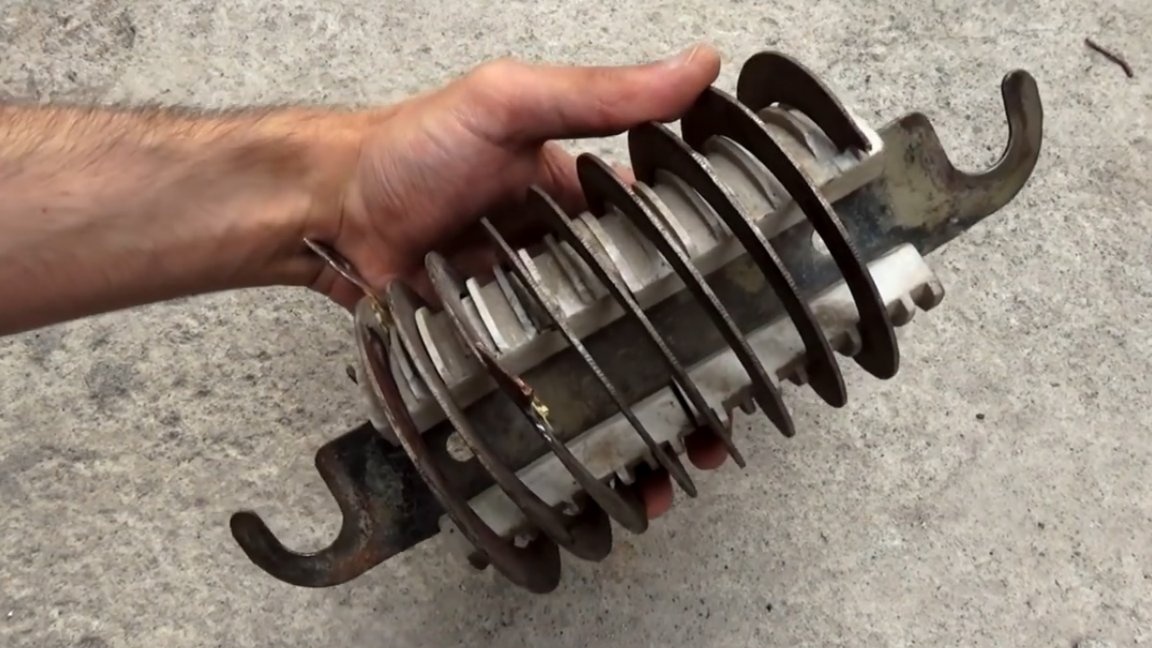
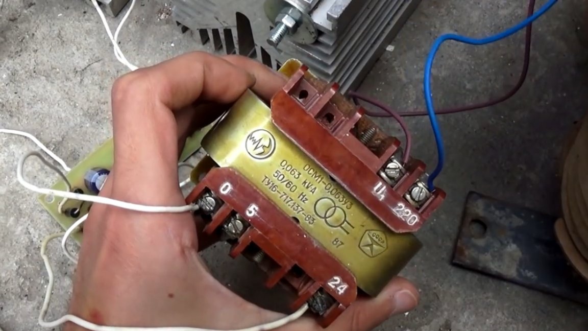
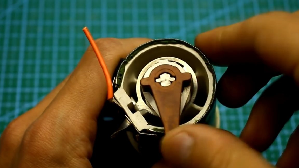
Not so long ago, the author of YouTube channel “AKA KASYAN” turned out to have such a three-phase power transformer from a deep vibrator for laying concrete.

The disadvantage of this transformer is that its windings are wound with an aluminum wire. And the plus is that the voltage of the secondary windings is about 36V.

In general, the author decided to make a home-made welding machine out of this transformer. The output voltage is sufficient for normal ignition of the arc.

Transformer welding machines were supplanted by more compact and lower weight inverter welding machines. But the indisputable advantage of transformer welding machines is extremely high reliability and long-term constant load.

The welding machine itself consists of 2 main parts: a power transformer and a welding current control system.


If the device is a direct current, then it also includes a rectifier.

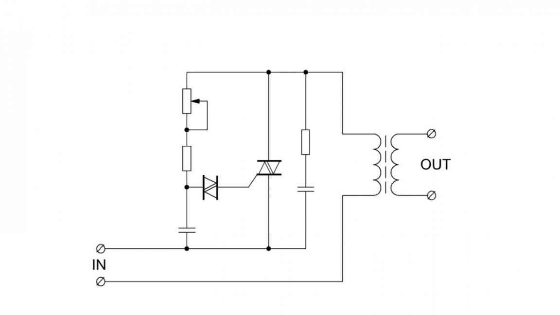
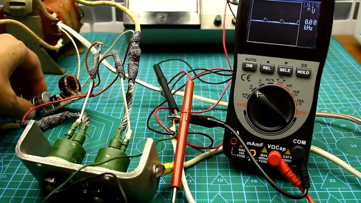
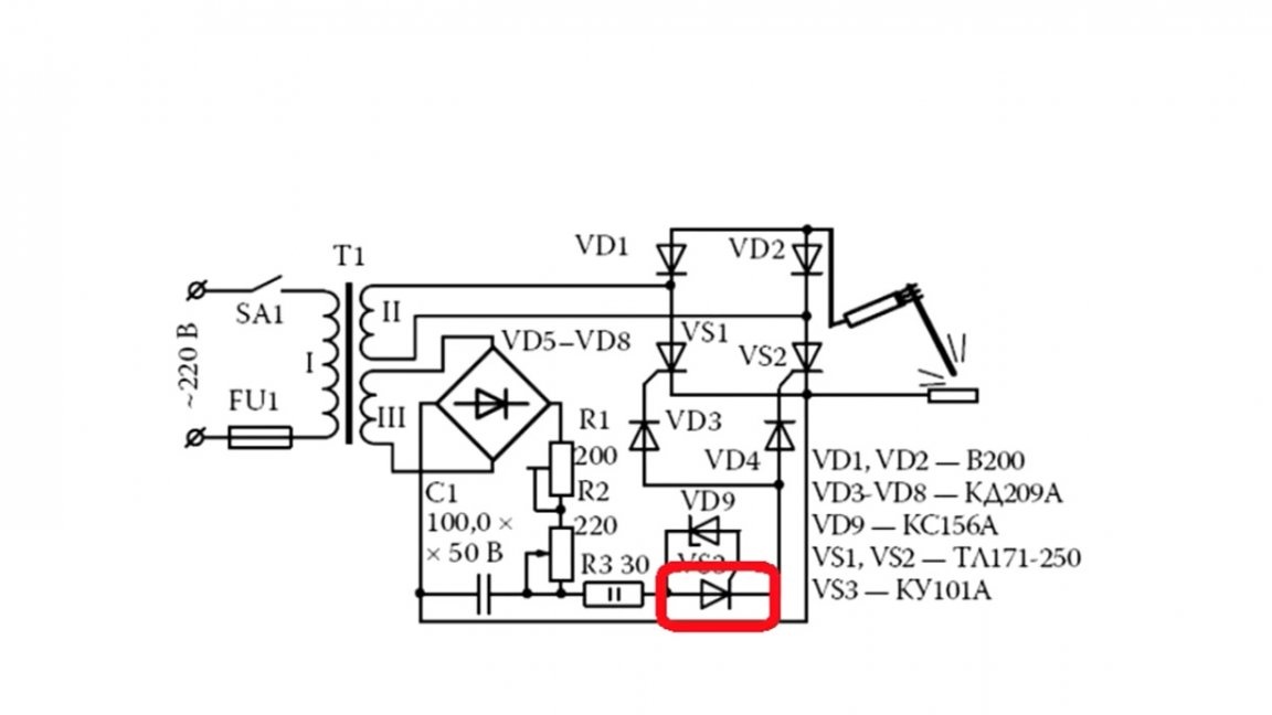
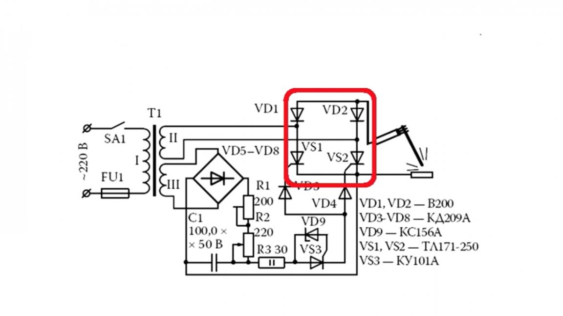
Below is a fairly well-known thyristor-based welding current control circuit:

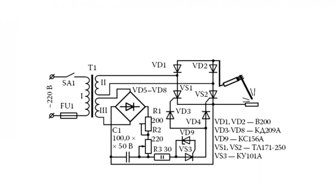
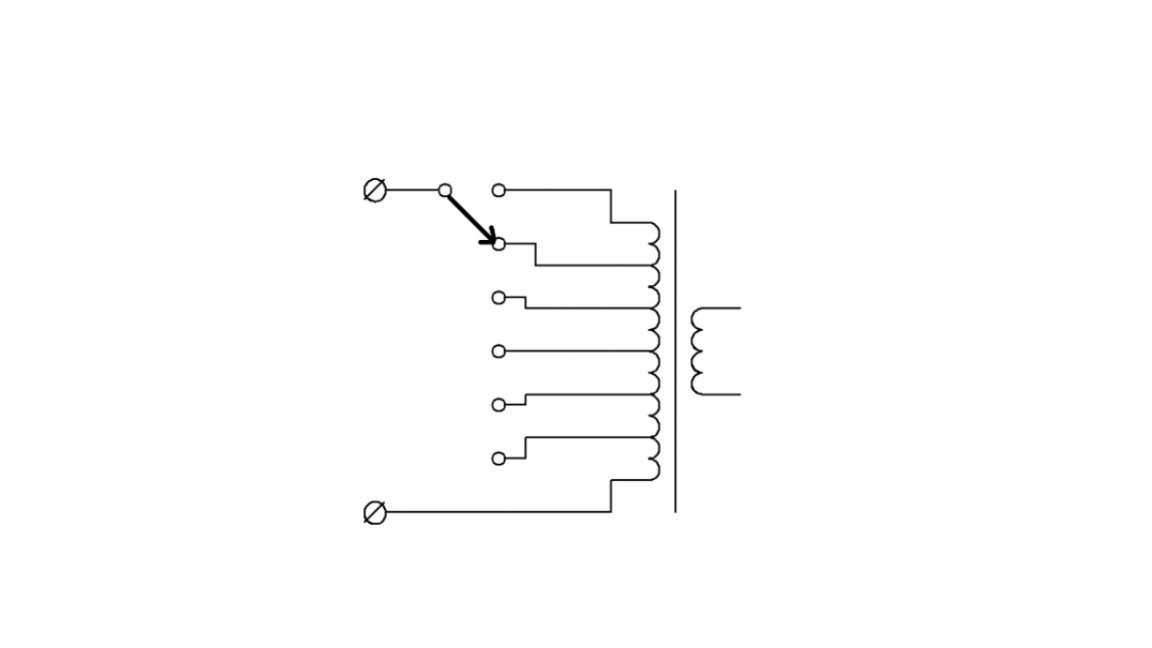
The welding current can be adjusted in several ways, for example, with a load ballast or resistance, switching the taps to the primary windings of the transformer, and finally electronic adjustment method, performed, as a rule, using thyristors.


Thyristor-based current regulators are extremely reliable and also have high efficiency due to the impulse regulation principle. What is also important, when adjusting the power, the output voltage of the welding machine without load remains unchanged, which means that there will be confident ignition of the arc in any range of the output current.

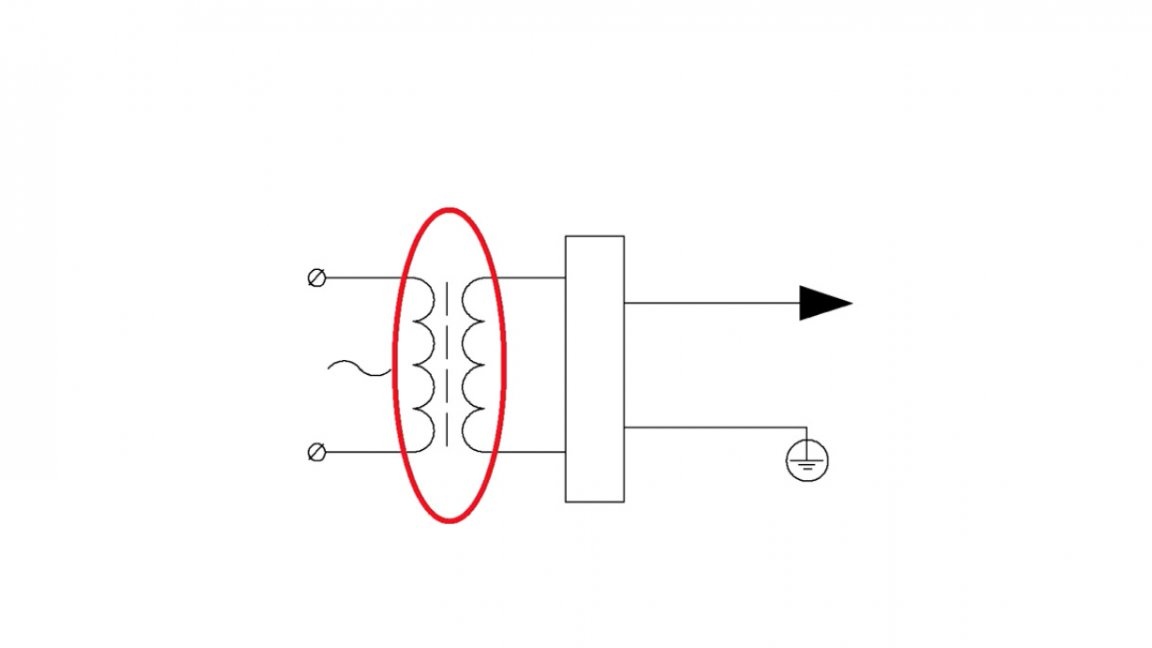
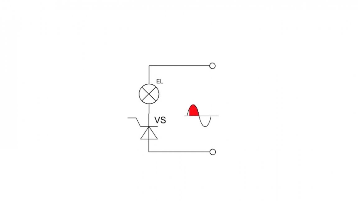
Power controllers can be installed as at the input of the primary circuit:

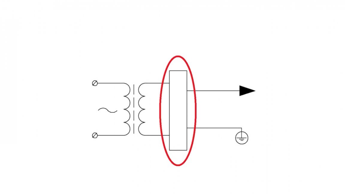
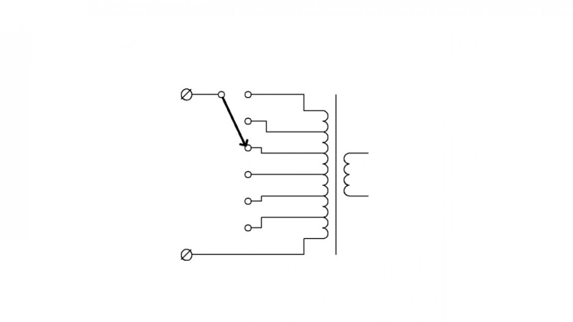
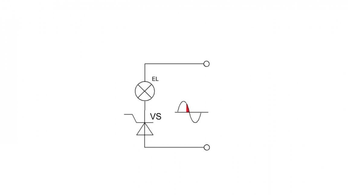
So at the output, after the secondary winding:

The problem is that the principle of power control using this type of controller is based on cutting off the initial sinusoidal signal, that is, parts of the sinusoid are fed to the load, and if the controller is installed on the primary circuit, irregularly shaped pulses will go to the transformer, which leads to the formation of a kind of sound, additional vibration and overheating of the windings.


But in spite of everything, these systems quite successfully cope with the inductive load, and if, moreover, there is a good and sufficiently reliable transformer at hand, then I think it's worth trying again.
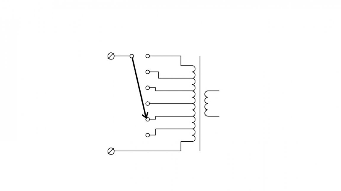
In this example, the current control system is installed on a secondary circuit.

This allows us to control the welding current directly. In addition, such a system, in addition to adjusting the welding current, will also serve as a rectifier, that is, supplementing the welding transformer with such a regulator, you get DC welding with the possibility of adjustment.
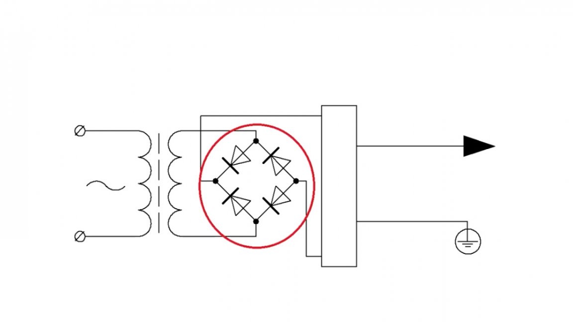
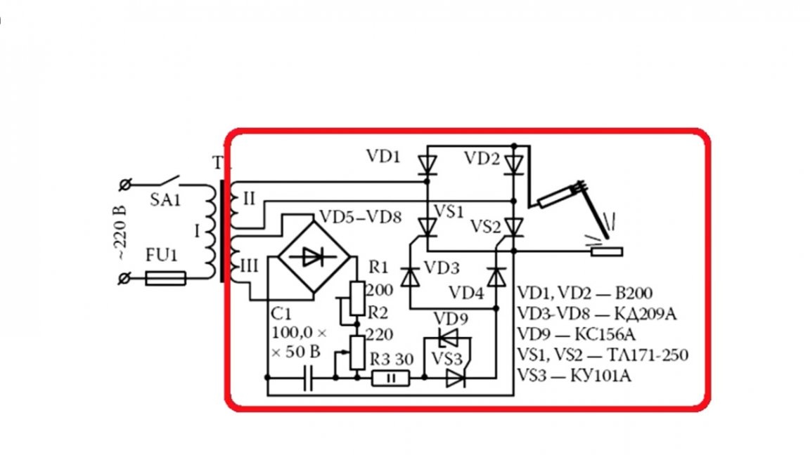
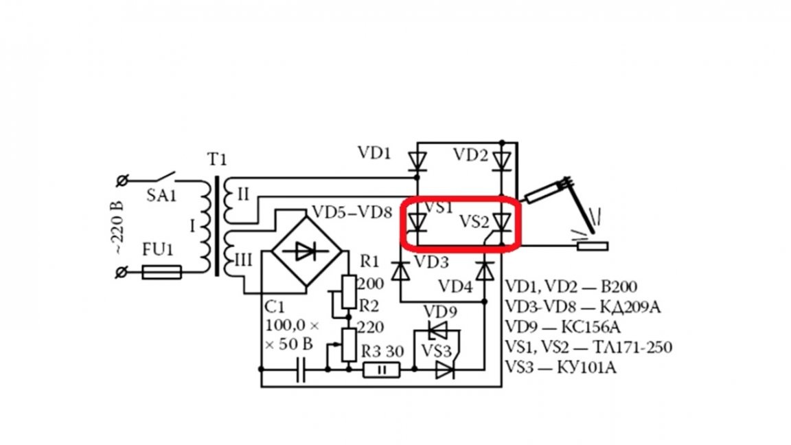
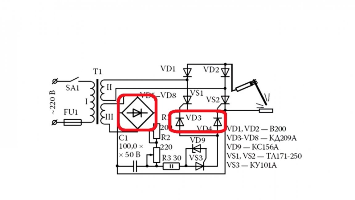
Now we will analyze the scheme of the future device in more detail. It consists of an adjustable rectifier:

It consists of a pair of diodes and a pair of thyristors:


Next is the thyristor control system:

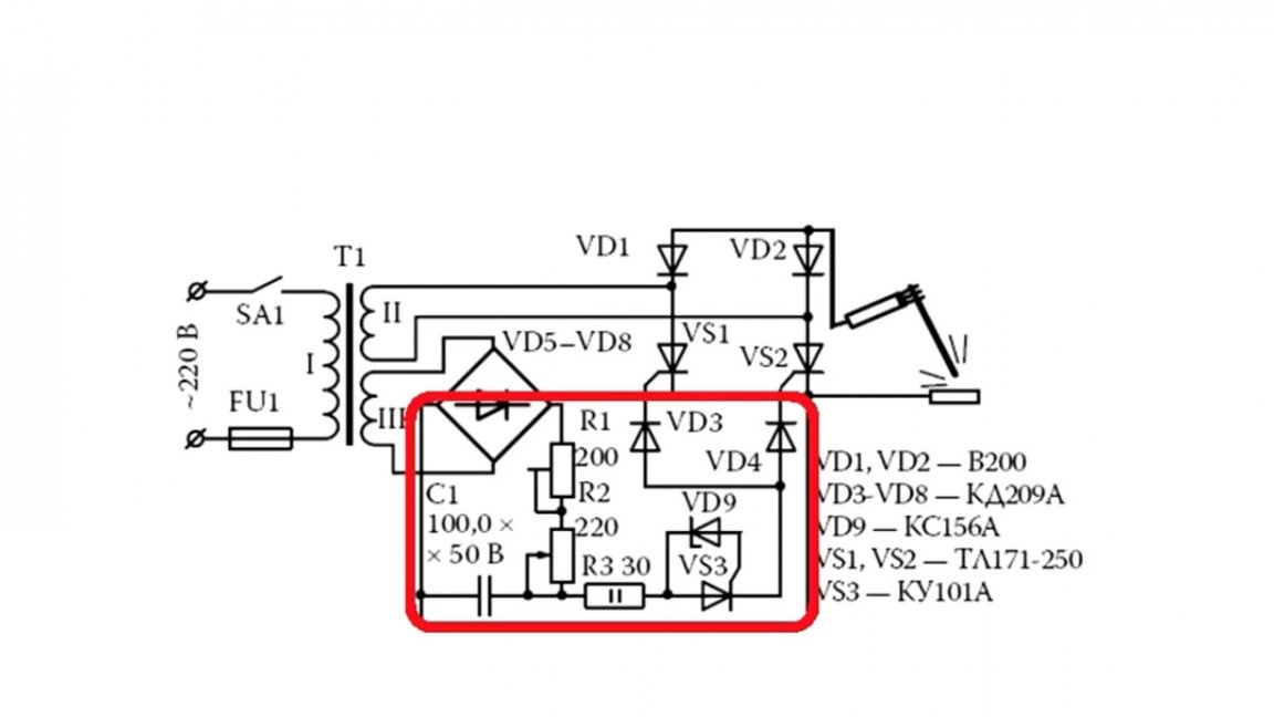
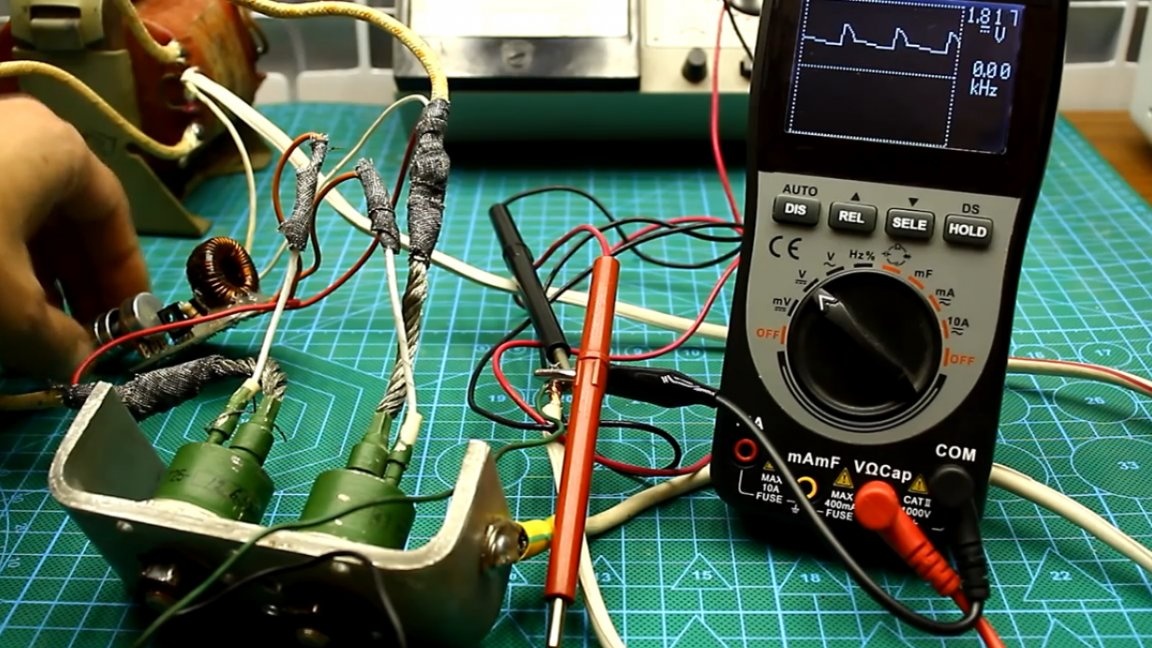
The control system in this example is powered from a separate low-power transformer with a secondary voltage of 24 to 30V with a current of at least 1A.

Of course, it was possible to wind a winding with the necessary characteristics on the main power transformer and use it to power the control system.

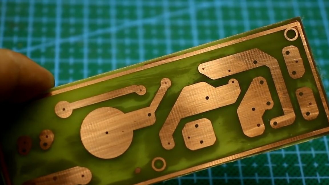
The circuit itself is made on a small printed circuit board. You can download it, along with the general archive of the project.


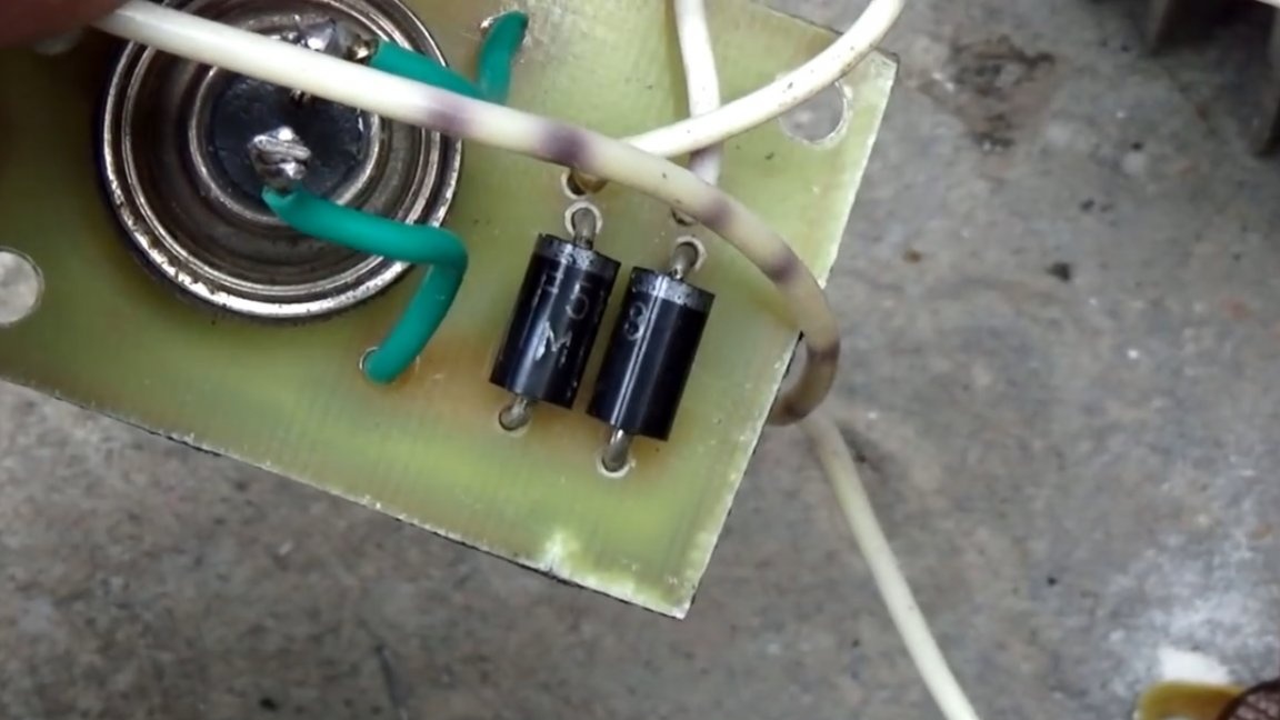
Thyristor can be used with any current of at least 1A.


In this example, the author used a 10-ampere, but this makes no sense, it was just at hand. The same with diodes, 1-amp is enough, but the current margin will never be superfluous.


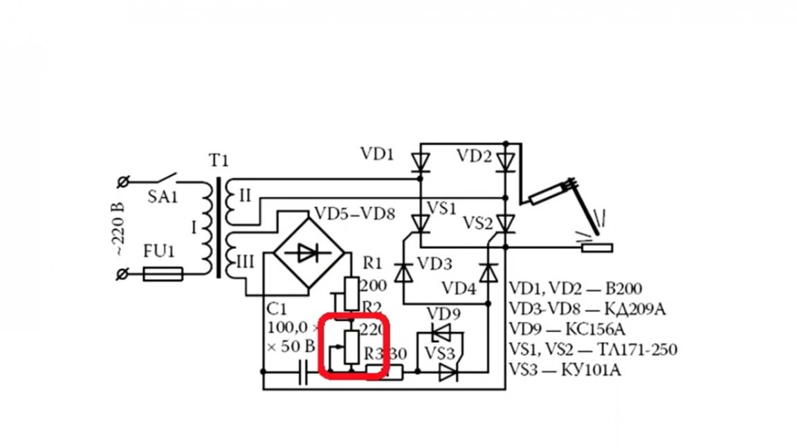
The upper knob allows you to adjust the limits of the output current.

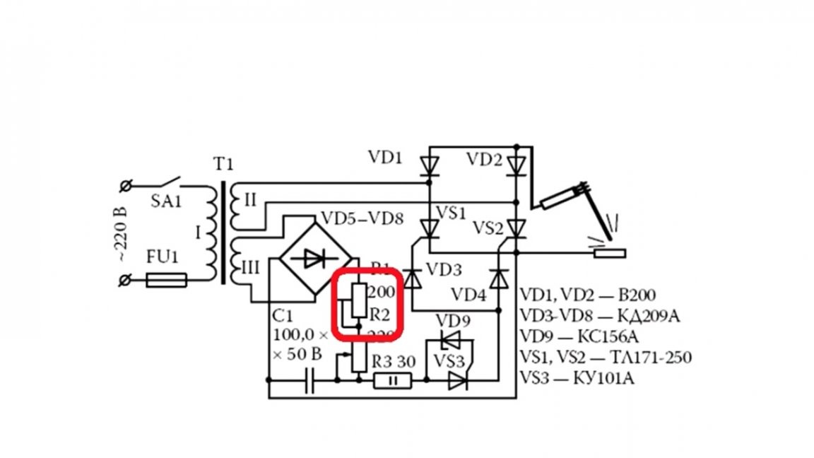
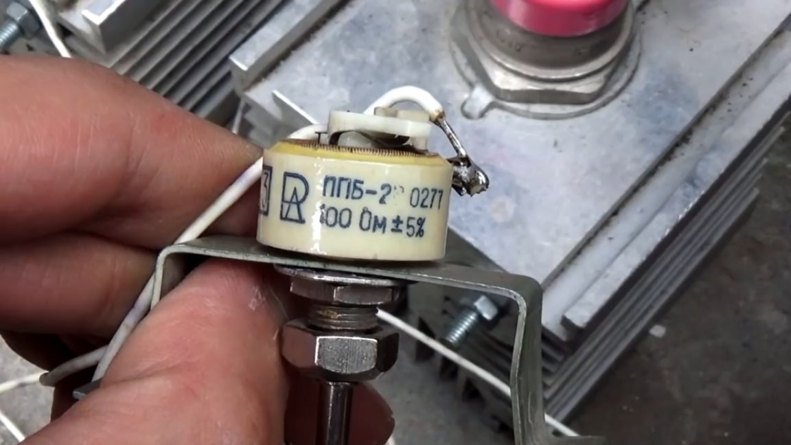
The second regulator is used to adjust the main welding current, here it is already necessary to use wire-wound variable resistors, preferably 10 or more watts.


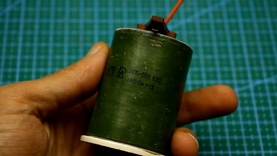
Initially, the author installed this monster:

But then it was replaced by such a less powerful one:

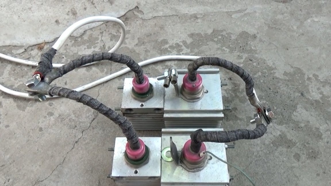
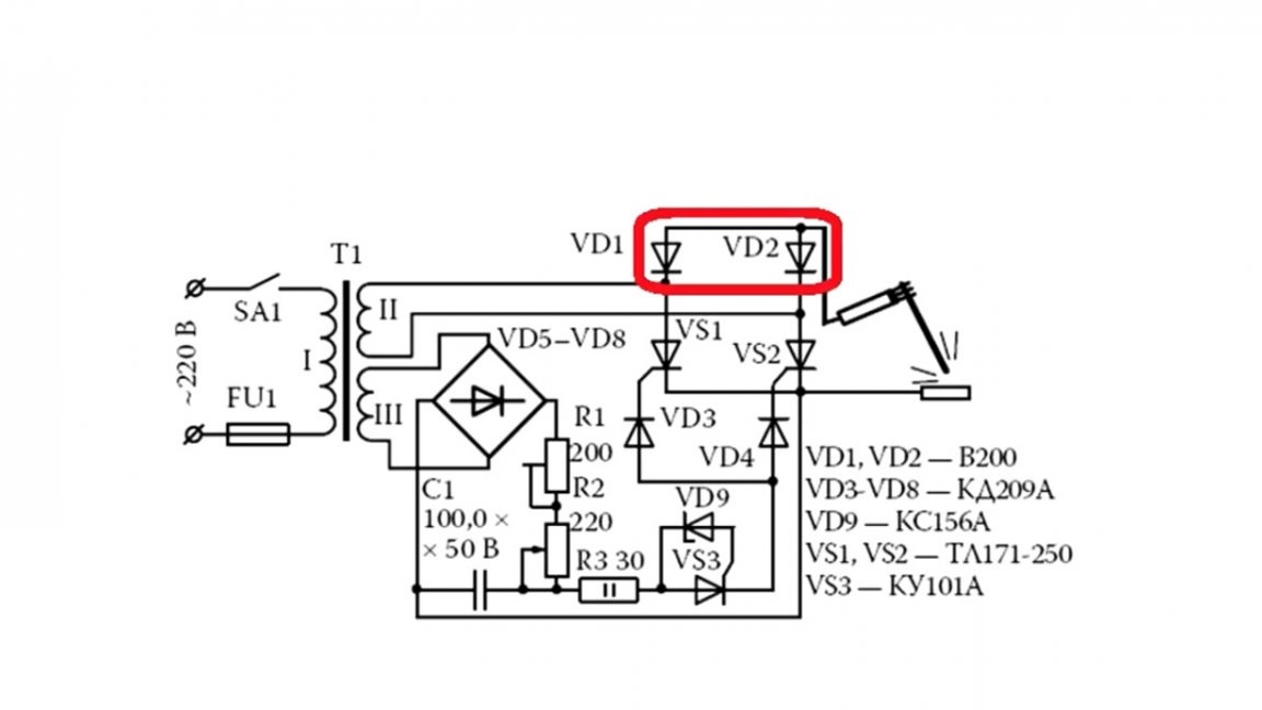
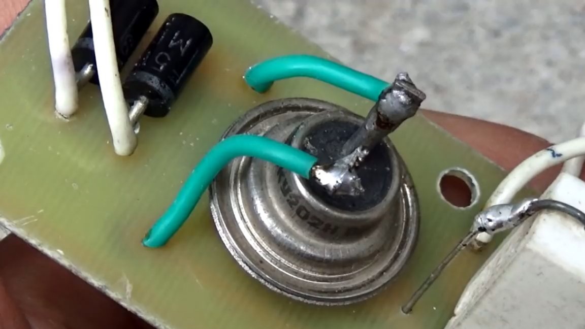
Now let's look at the power rectifier:

The diodes and thyristors used here, despite the monstrous appearance and excellent characteristics, were bought at a flea market literally for a penny.

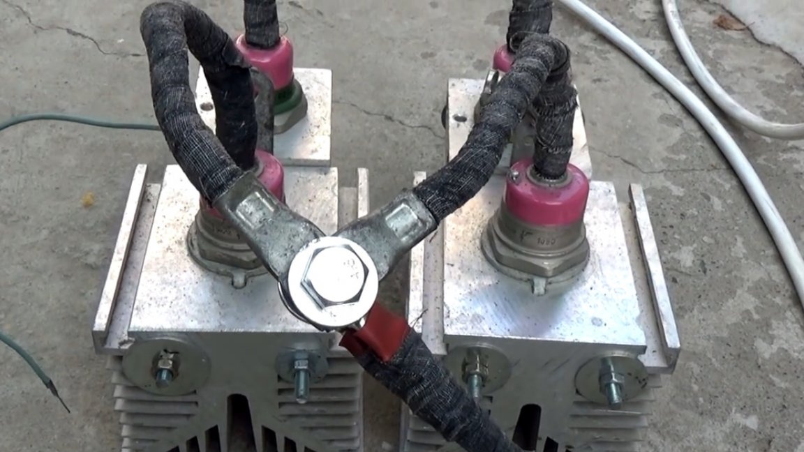
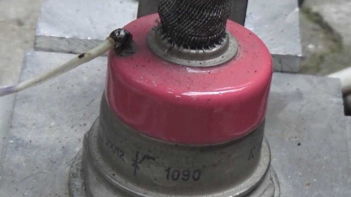
These diodes are type B200 with a current of 200A, the reverse voltage also depends on the index. In this case, 1400V. But the thyristors are more powerful T171-320.

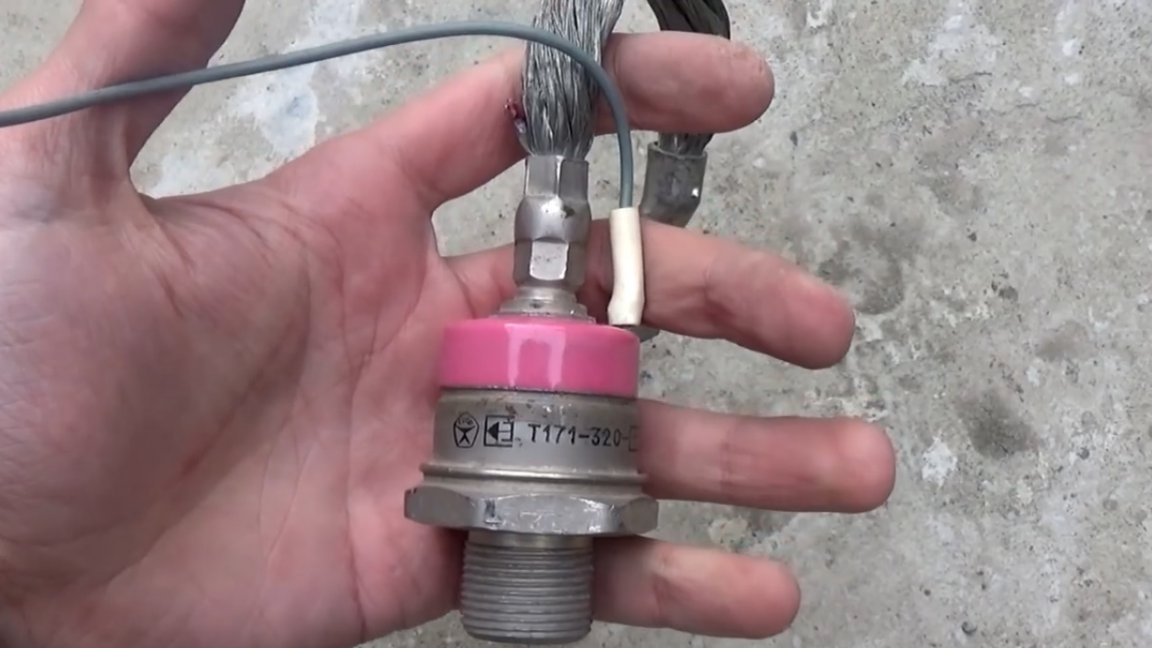
Such thyristors are designed for currents as high as 320A. The current in shock mode can reach up to 10000A. Of course, these diodes and thyristors are capable of more, and they will not burn out even at currents of 300-400A. And also these components were produced back in the USSR, that is, their characteristics are in no way inflated by the manufacturer.

The disadvantages of such a regulator can be attributed only to the large weight and decent size.
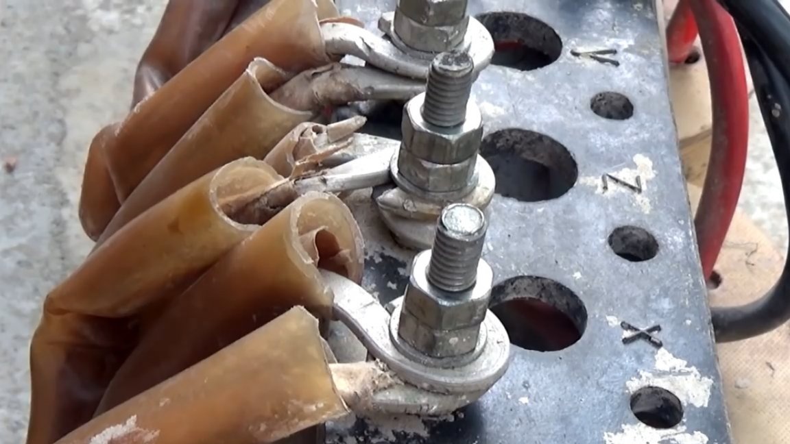
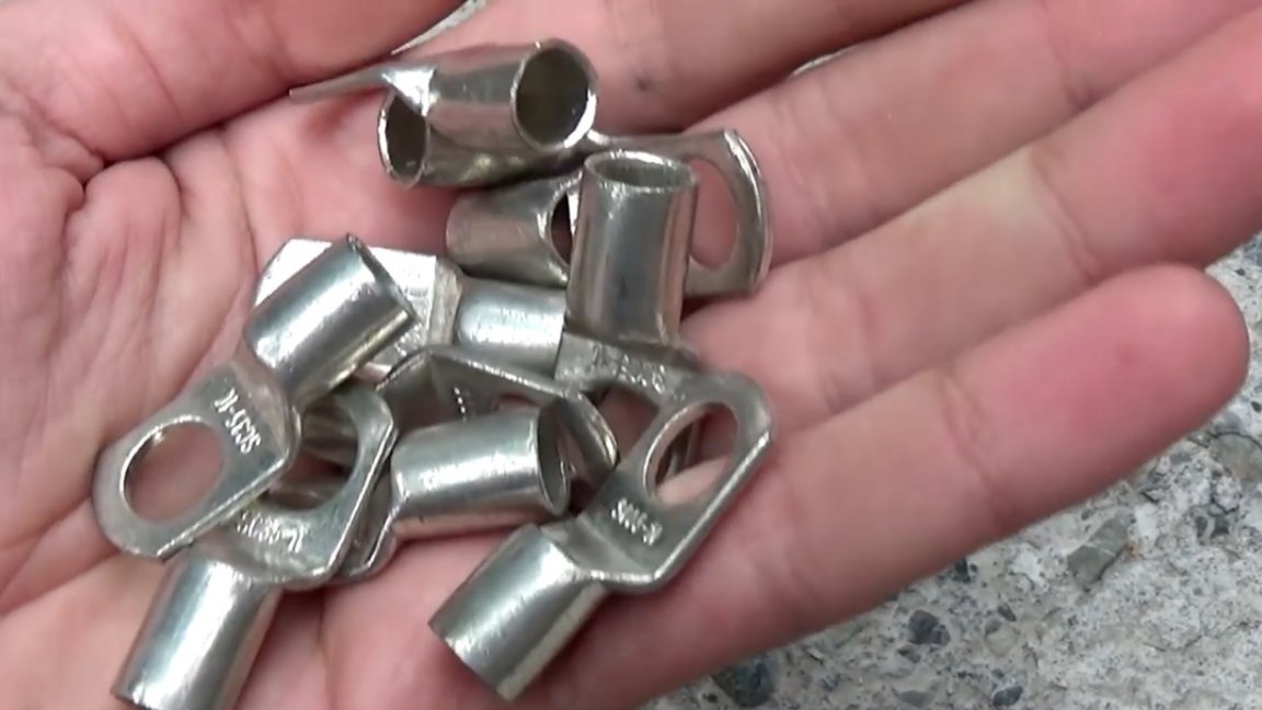
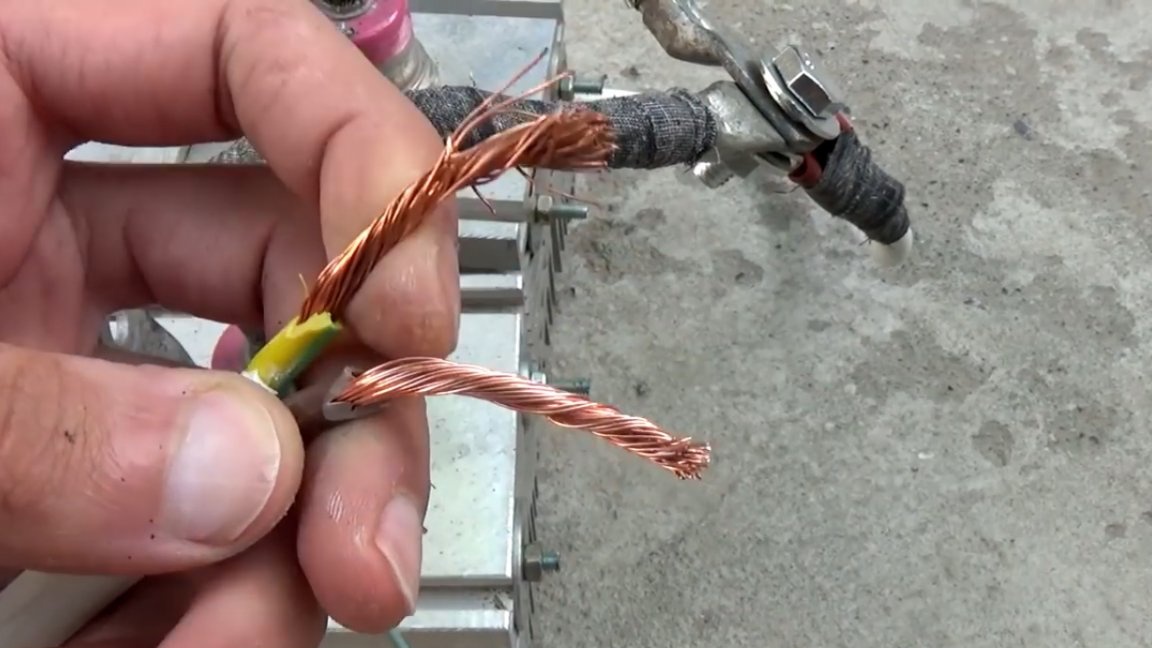
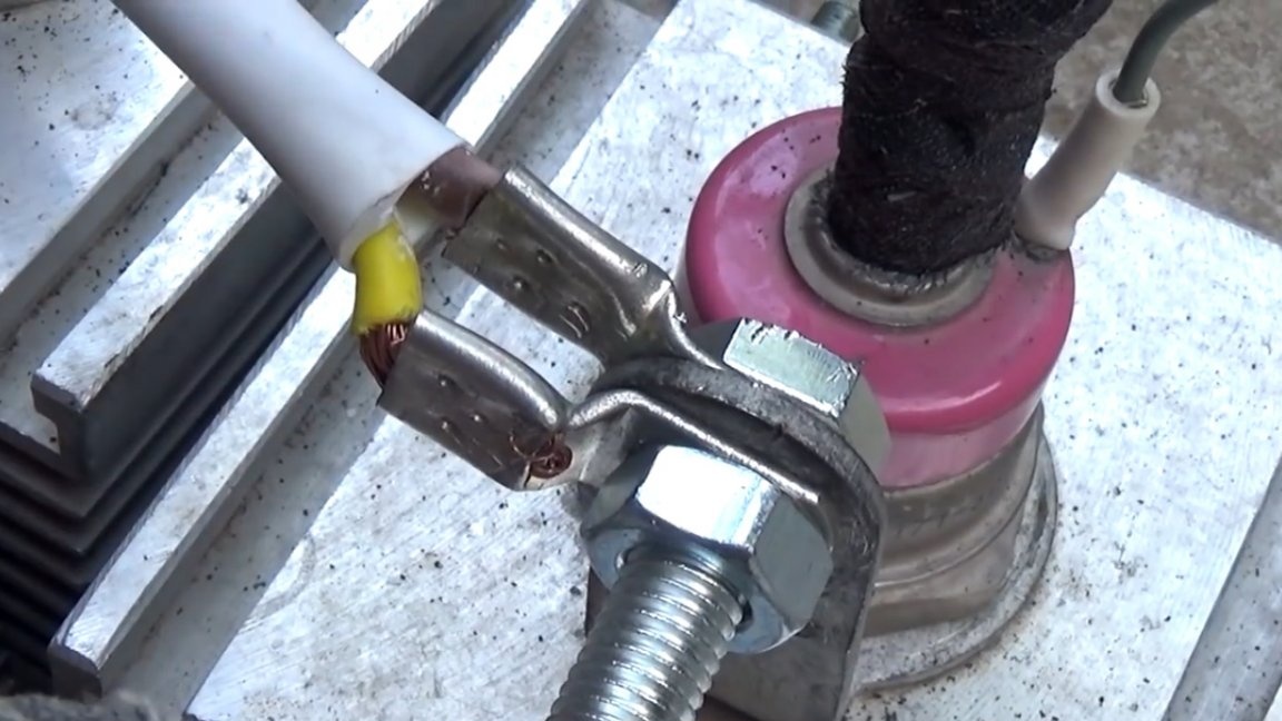
For all power connections, the author applied tinned copper terminals. Such can easily be purchased at almost any hardware store, they are not expensive.


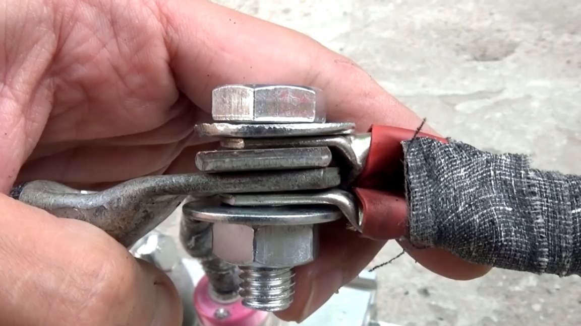
Wires 2 to 6 squares in parallel, of course not enough, but they are copper.


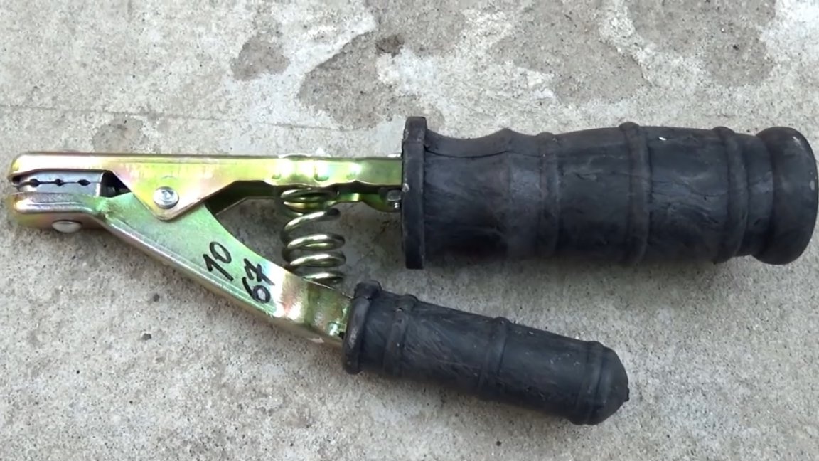
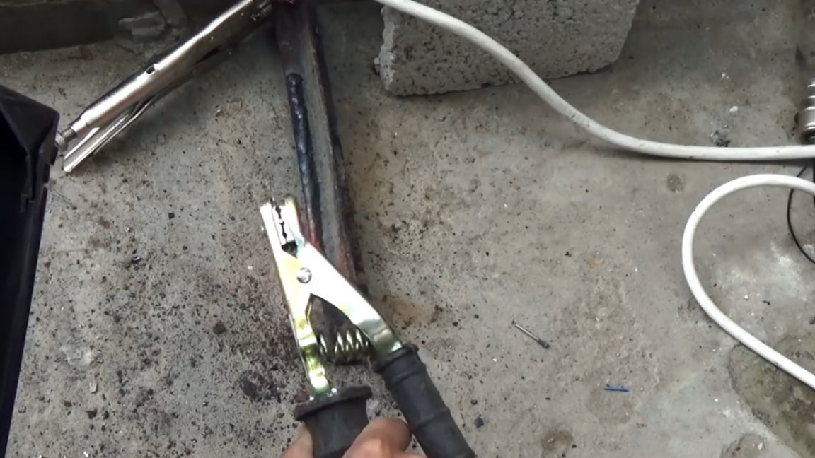
The author found the electrode holder in the nearest hardware store, which was not very convenient of course, and the workmanship was poor, but what it was.

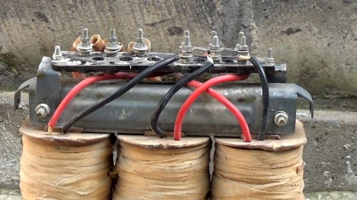
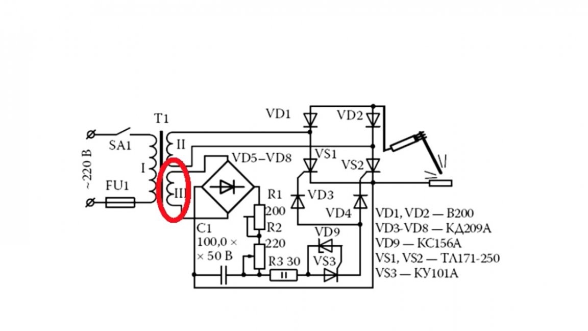
Now back to the transformer. Since we have a three-phase power transformer, and it will have to work in a single-phase network, we will have to switch the windings. Each coil has its own primary and secondary winding.

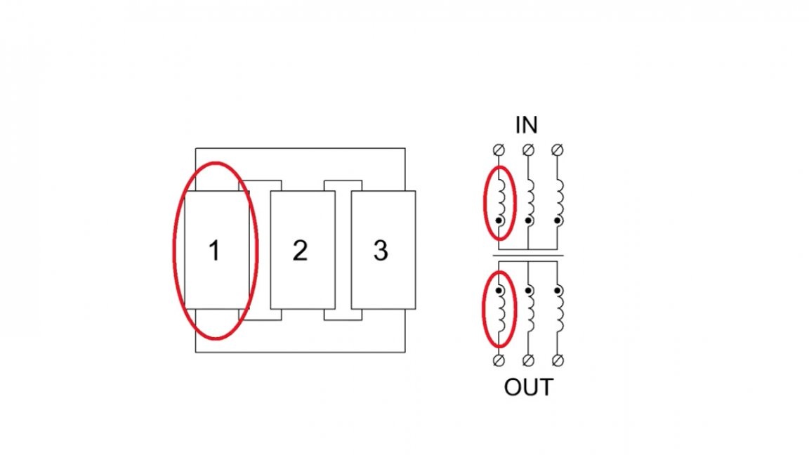
The author excluded the central coil.

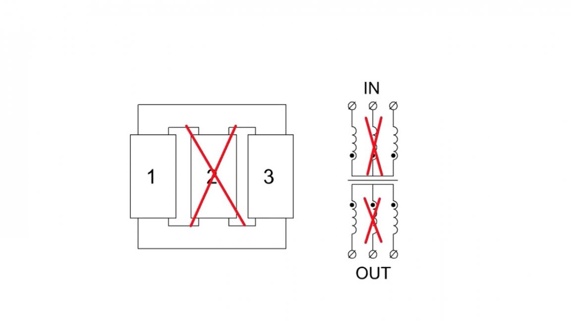
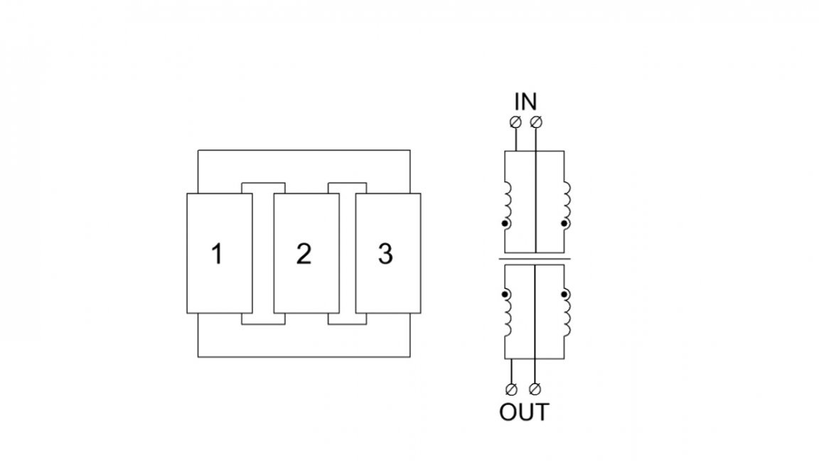
Two extreme coils are connected in parallel, both on the primary and secondary windings for operation from a single-phase network.

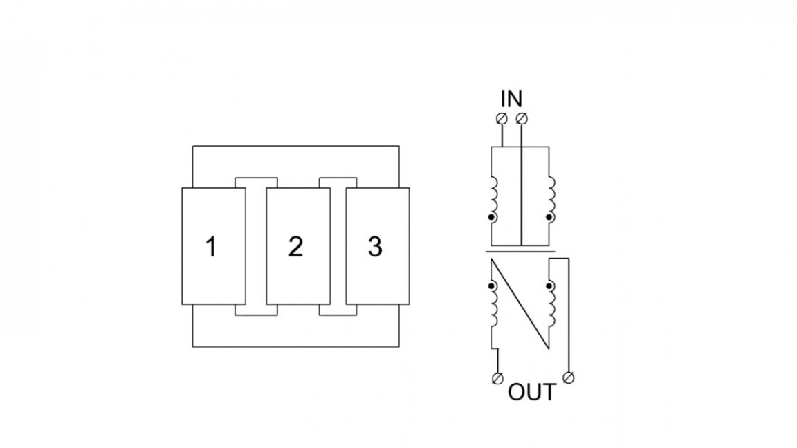
But during the experiments it turned out that, taking into account the losses on the rectifier, the voltage is not enough for the normal ignition of the arc, so the secondary windings had to be connected in series to increase the total voltage, the current would be 2 times less, but what to do.


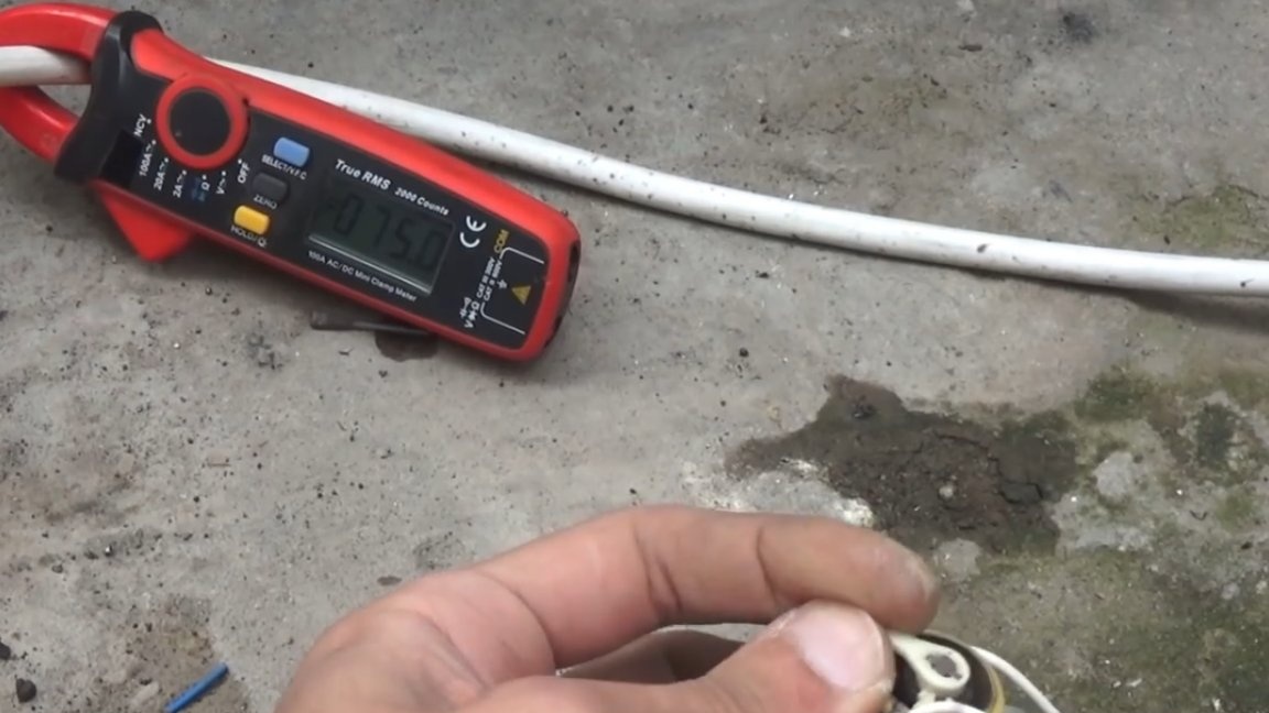
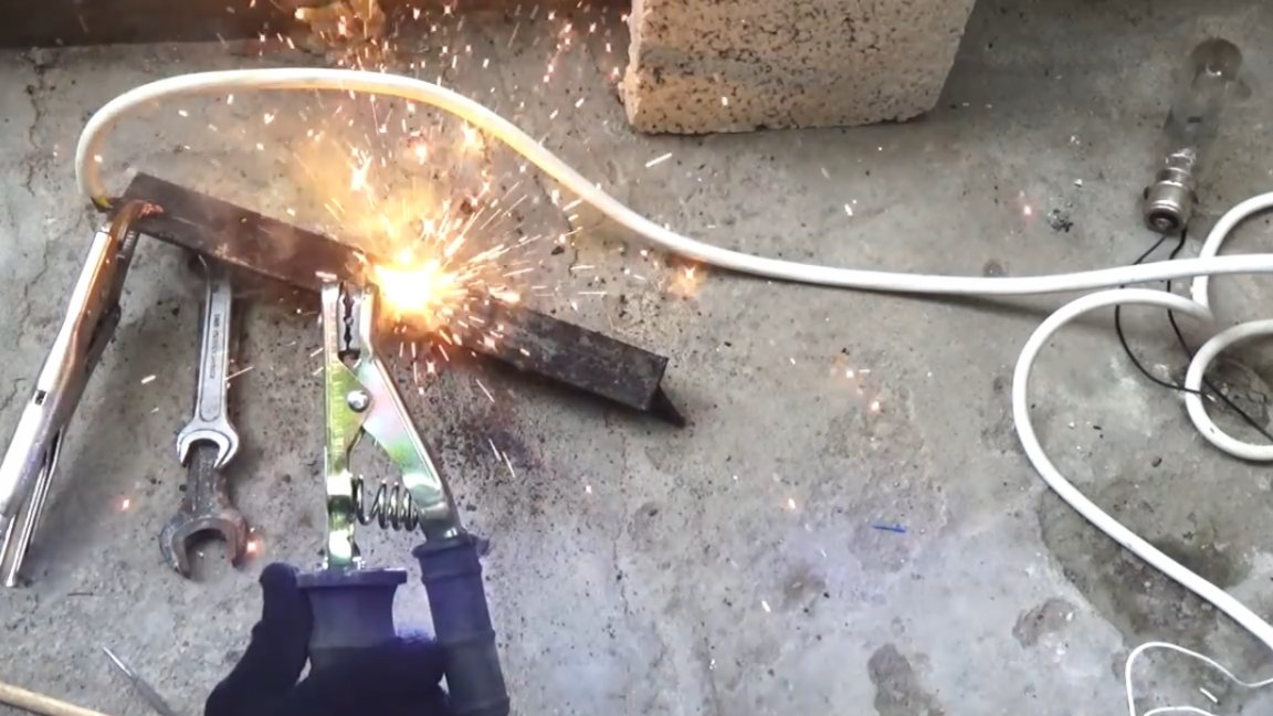
At currents of 75-80A, this transformer begins to overheat and stink, and so the control system in this design can easily be used for currents of 200 or even more amperes.


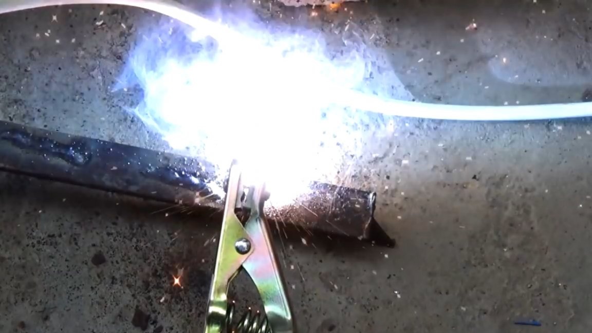
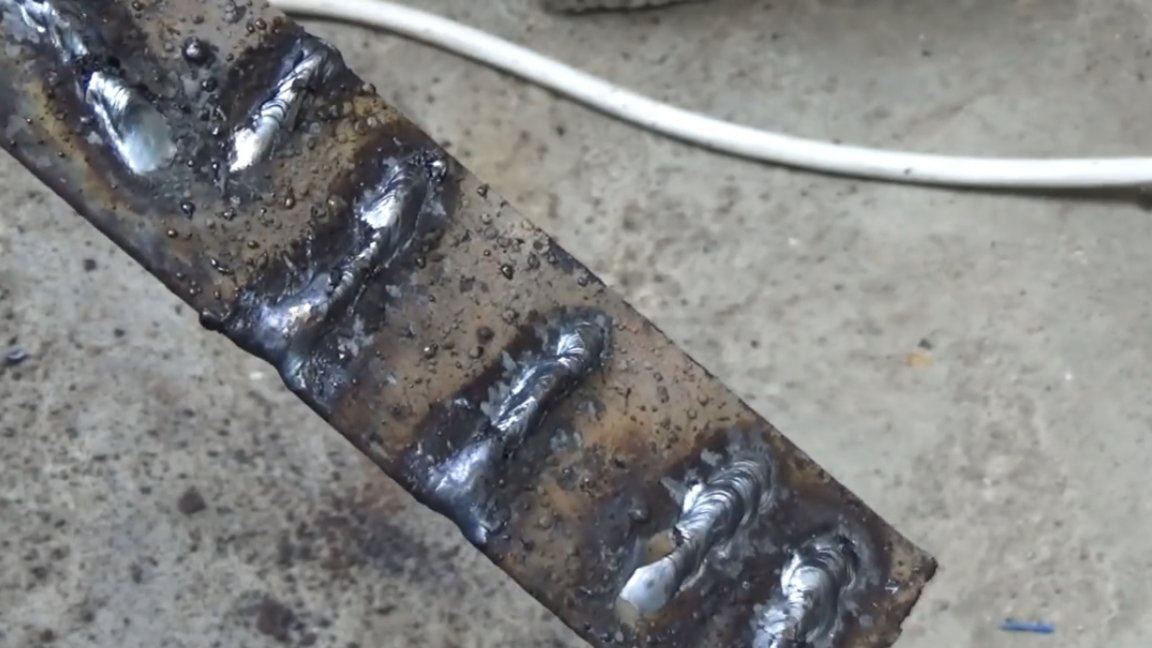
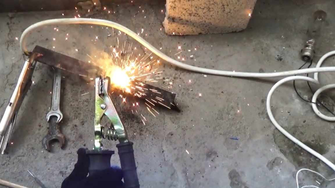
After burning 3 electrodes, the author realized that the transformer was very hot, yet it was not intended for such tasks, but in this case we checked the current control system, and it works well.
That's all. Thank you for attention. See you soon!

Author's video:
6.5
6.8
5.5

Add a comment

    • smilesmilesxaxaokdontknowyahoonea
      bossscratchfoolyesyes-yesaggressivesecret
      sorrydancedance2dance3pardonhelpdrinks
      stopfriendsgoodgoodgoodwhistleswoontongue
      smokeclappingcraydeclarederisivedon-t_mentiondownload
      heatirefullaugh1mdameetingmoskingnegative
      not_ipopcornpunishreadscarescaressearch
      tauntthank_youthisto_clueumnikacuteagree
      badbeeeblack_eyeblum3blushboastboredom
      censoredpleasantrysecret2threatenvictoryyusun_bespectacled
      shokrespektlolprevedwelcomekrutoyya_za
      ya_dobryihelperne_huliganne_othodifludbanclose
12 comments
For most familiar electronic engineers, the phrase AKA KASYAN causes an attack of an uncontrolled swear.
Rashid.
Gentlemen Kulibin, all this is the last century, you still won’t get a constant, it’s not worth the hassle. You can now buy an inverter for 3,000 rubles. Many years ago, in a gathering of citizens of the village, we decided to ban cooking with home-made welding machines, in the village. And you probably guess about the reason.
Maximus _
He made a similar welder, a German transformer, from a 20 kilowatt voltage regulator.
Thyristors are also German, with an electric drive of 110 kW of printing unit.
I put a choke at the output, in order to at least somehow smooth the current, they cut it with an 5 mm electrode, the welders were in shock, with a current of 50 amperes at 220V each. The current with strong ripples, in comparison with a three-phase welder, sucks.
It was sent to the colorimeter when an inventory welder appeared.
By the way, there is a big mistake in the bridge circuit, interchange one diode and thyristor. The control circuit is a little complicated, pulse transformers are needed to control the thyristors, but the diodes will suppress the reverse voltage.
Guest Dmitry
The idea is good.
But: for manual arc welding, it is important to ensure the falling characteristic of the power source. If the transformer has movable coils, this is what it is. If the alteration of the power transformer - you need a ballast rheostat (resistor) or inductor. If you do not pay attention to the characteristic, a poor welding machine may work. A good welding arc is "elastic", it can be stretched, it burns steadily with little spatter. And it may turn out that you stretch it, it breaks off (or the hand faltered, it cuts off), when burning - the spray flies in all directions. The quality of welding will deteriorate.
Guest Andrey
I made such an adjustment from an old vacuum cleaner. He pulled out the speed controller, replaced the triac with a 40 amp and set it on the input. Simple and reliable.
Less to you is not for the text, since it is impossible to read it, but for the fact that, having changed your nickname, you continue to yell. ((
turn off the capsules and do the paragraphs, and then the blood from the eyes
PHASE
HELLO! VERY WELL WRITTEN, I LIKED! I AM ALSO FOR 20 YEARS DONE IN WELDERS, BUT ANOTHER ... I HAVE A FACTORY WELDER I AM SURELY 40-50 YEARS, BUT IT IS ADVANCED - SIZE WITH TABLET (Lying on the side), I WILL PREVENT IT SHUNT ... SHORT VERY COOL FOR SOVIET TIME! Well, I have the OPPORTUNITY TO BUY POWERFUL DIODES OF CHEAP AND I DECIDED TO ASSEMBLE THE DIODE BRIDGE ON IT! BORN TO EL. WORKSHOP, (I WORKED CHAPTER ENERGY AT A SMALL FACTORY AND FREE TIME WAS ...), TAKEN OUT THE CASE, AND THIS WAS SEEN IT BY MY POSITOR ... LOOKED, ASKED ... AND SUGGESTED THOSE !!! WE WOULD DO, THE TRUTH INCREASED A LITTLE CROSS-SECTION OF THE CORE AND THE WIRE-WIRE OF THE WINDING. MATERIALS WERE ALL FROM THE POWER TR-PA 10 / 0.4 kV I HAVE BEEN SORRY FOR THE RECEIVER, HE CUT IRONLY WITH SIMPLE SCISSORS ON THE METAL AND HANDS WASHED BEFORE BLOOD AND BEFORE BLOOD ... BUT SOMETHING AFTER STOP. FOR THIS TIME I ALREADY ASSEMBLED A RECTIFIER BRIDGE AND I HAD TO ASSEMBLE ITSELF AND INSTALL THE UNIT TO IT. In short, EVERYTHING WE GATHERED, TESTED AND TESTED! HE WORKED NOTHING WELL BETTER MY !!! MAYBE BETTER ...TESTED FOR EVERYTHING, INCLUDING AND FIVE ELECTRODES AT FIVE CURRENT, AND BURNED AT LEAST 5 ELECTRODES WITHOUT A BREAK! THE APPLIANCE ONLY WAS HEATED A bit - DEGREES 40-50 ... WELL IT HAS ALSO LITTLE ONE TO MAKE A DIODE BLOCK, AND I WAS ONE TO TAKE THE THYRISTOR REGULATOR, SO I HAVE APPEARED 300! SEARCHED A SCHEME AND FIND IN THE MAGAZINE A RADIO ARTICLE WHAT IS TYPE * THYRISTOR? IT'S SIMPLE*. Well, in short, I took the simplest scheme, the demonstration, where the light bulb lit up smoothly ... I collected it on my high-power parts, I picked up what it was necessary for details ... AND EVERYTHING !!! I UNDERSTAND THAT EVERYTHING I HAVE DONE Primitively, BUT EVERYTHING WORKS PERFECTLY !!! BECAUSE AND THE POSTER COLLECTED THE SAME REGULATOR. A WELDER AND NOW AT ME, STANDS IN THE GARAGE - 10 STEPS BEFORE HIM, BUT ... BUT 5-6 YEARS BACK I BOUGHT MODERN - INVERTER, I HAD TO MAKE A FENCE, AND THE STATION ARE SMALL SEPARENT ALREADY! WHAT I FOUND I DOED ON myself, AND I PUT UP PILLARS AND BREWED AND IRONED ... Well, SHORTLY, THE OLD WELDER HAS WORKED 50 YEARS AND NOW IN EXCELLENT CONDITION, AND IS INCREASED LOW ... BTW, THE PALACE IS TAKEN USE OF OUR HANDMADE COPY AND THE INVERTER IS NOT GOING TO BUY !!! WELL IT'S A LITTLE SKINY, ADDICTIVE OF THE USED, AND I AM ADVANCED !!! I LOVE EVERYTHING NEW !!! xaxa WRITTEN SIMPLY SO, JUST NOW THERE HAVE THINKED - HOW DO WE SUCH SUCCESS? Because we then did not know anything and did not understand !!! ONLY MY SMALL THEORETICAL KNOWLEDGE ... IF HONESTLY, THEY WERE WELL VERY SMALL !!! BUT WE WERE BOTH FACTORS AND FUN !!! HERE AND START UP ... xaxa xaxa
Guest Vladimir
Such adjustment for the secondary did on homemade trances back in the 80s. I made 2 or 3 to order. I didn’t do it for myself (cumbersome), and I didn’t find any more components. I tried on the primary. I also made a couple to order, but I didn’t like the fact that in some position of the alternator an unpleasant sound arises, sort of like a resonance. During commissioning, dinistors used to burn out.
I can tell a lot about this shaitan machine, since I remade a great many of them. Firstly, the author of the video repeats all my mistakes, namely, left the central rod with the windings, the Transformer must be disassembled, remove the central rod plates and long jumper plates, then assemble using only the side rods and short plates, they are enough in the most accurate way. Thus, the length of the magnetic circuit and, accordingly, the losses in it are reduced (we decrease the magnetic resistance). Further, if desired, you can wind up the working coils with a freed-up central winding wire (of course, until the final assembly, there is enough space there), thereby increasing the voltage of the secondary winding and gaining the ability to adjust the taps along the primary, but this is a small digression.
Secondly, let's look at the schemes a bit. The beginning of the windings is usually denoted by dots, which is done on all schemes. Now imagine the instantaneous value of the current direction (for example, from beginning to end) and, accordingly, the direction of the magnetic induction vectors created by the coils (the coils are wound in one direction). We get a short circuit of the magnetic circuit (this does not happen with the central rod since the oncoming magnetic flux goes to it, which, by the way, explains the low return in the secondary winding and the heating of the transformer). The windings are connected in parallel to the beginning of one with the end of the other, then the magnetic flux in the magnetic circuit will become annular.
Now, on the secondary winding, there the wires are also connected in parallel, and the author’s complaint about the insufficient arc ignition voltage due to losses in the rectifier has no reason, since the rectified open-circuit voltage will be equal to the amplitude voltage, which is 1.4 times greater acting, and it completely covers losses in gates and thyristors (about 3-4 V), this is the result of losses in the magnetic circuit. By the way, even a 24-volt transformer can be cooked, the arc really ignites worse, but it can.
Thirdly, again according to the scheme, the article does not show the last scheme from the video, which is precisely the working one. Without a smoothing inductor, just after the rectifier and even with the adjustment in which part of the half-wave is cut, the operation will not differ much from AC welding in terms of arc stability. For the inductor, you can use the secondary winding wire from the removed central coil by wrapping it on a separate magnetic circuit in two wires (the cross section of the inductor winding should be no less than the transformer winding).
P.S. And as for the complaint of the video’s author about the strong heating of the transformer after three electrodes, I can say that I not only cooked with such transformers (with a corresponding alteration), but even cut the metal. Of course, the trance was warming up, but it didn’t stink after three electrodes, for example, my father and I without special breaks cooked a 2x3 m fence. (He taught me how to weld, I made the apparatus, but I didn’t know how to cook yet).
Guest Sergey
simply and reliably the fan to put protection the machine to pick up nothing to break
this hand-made steampunk xaxa good

We advise you to read:

Hand it for the smartphone ...