
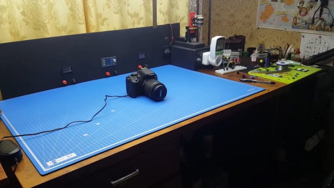
In this article you will learn how Roman, the author of YouTube channel “Open Frime TV”, from an old scanner do it yourself made a slider for the camcorder (camera).
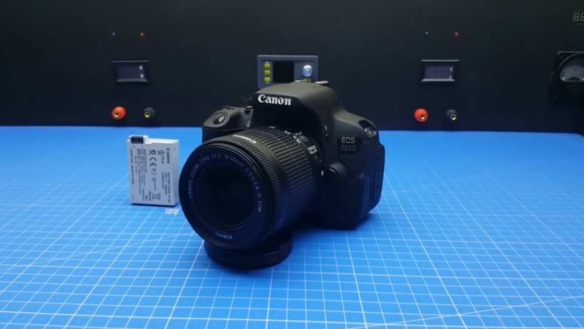
Let's start with a short introduction in the form of background. At some point, the author had a desire to improve the quality of the videos he shot for his YouTube channel. As a result, it was decided to purchase a SLR camera. Using it, making beautiful shots will become much easier, the author thought, but not everything turned out to be as simple as it seems.
Firstly, a mistake was made when choosing a camera. As you know, there are 2 fundamentally different types of focusing: contrast and phase. Contrast focusing does not know where the focus object is moving, and therefore it starts to pull the lens in different directions in search of contrast, but the phase focusing device is different.
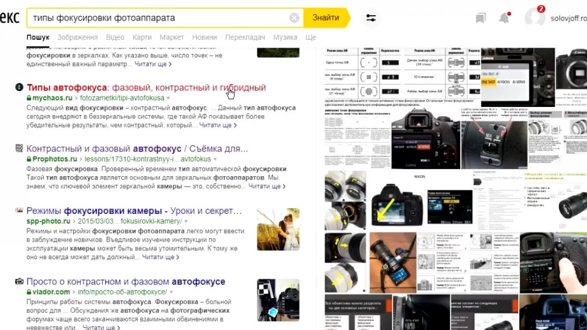

During phase focusing, access occurs to a special sensor built directly into the camera’s matrix. This sensor is able to track the distance to the object and rotate the camera lens in the desired direction.
The author also wants to share a small life hack. As you know, the camera’s battery capacity is not very large, and sometimes you have to shoot a lot.
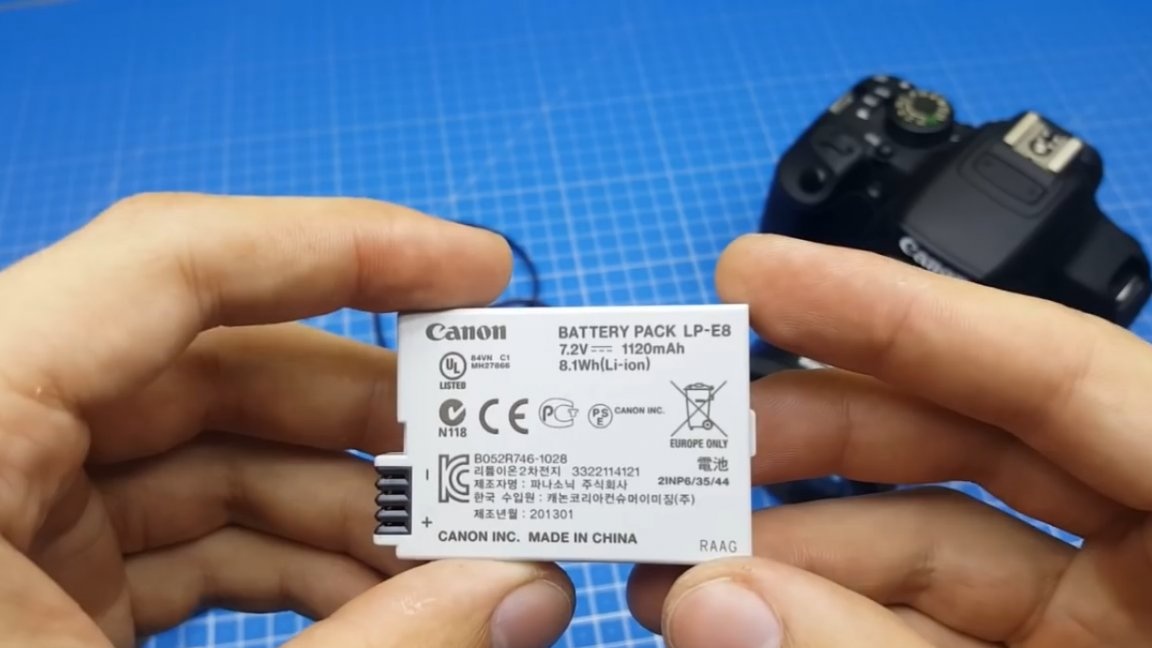
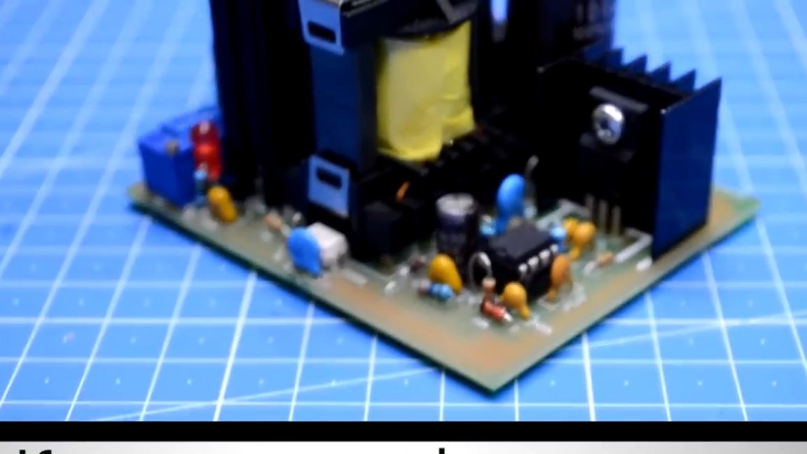
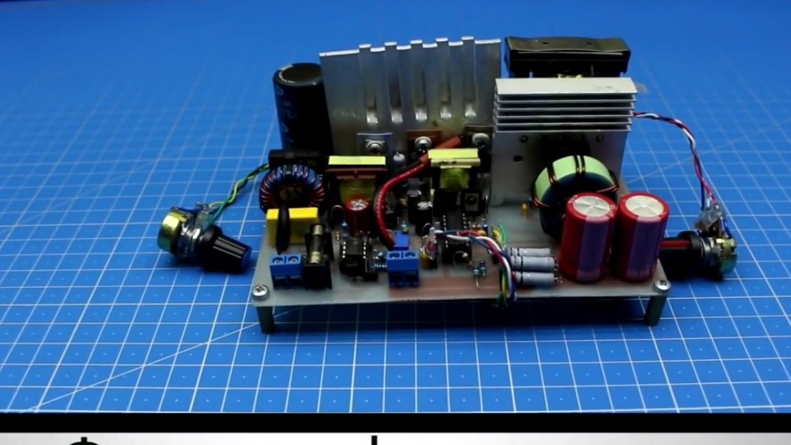
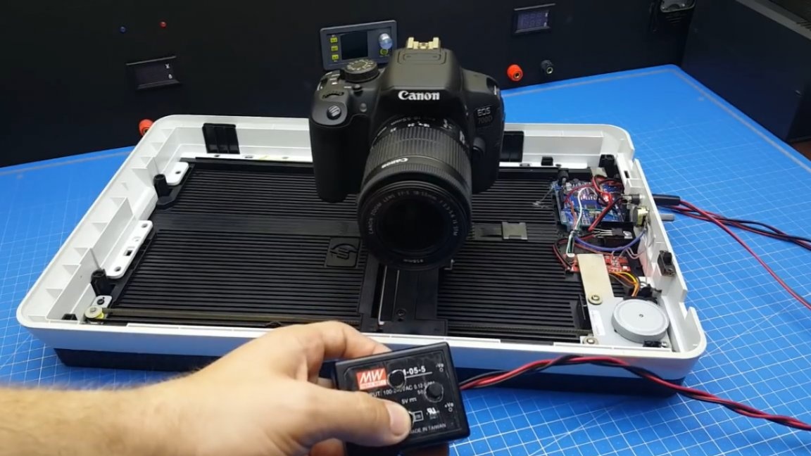
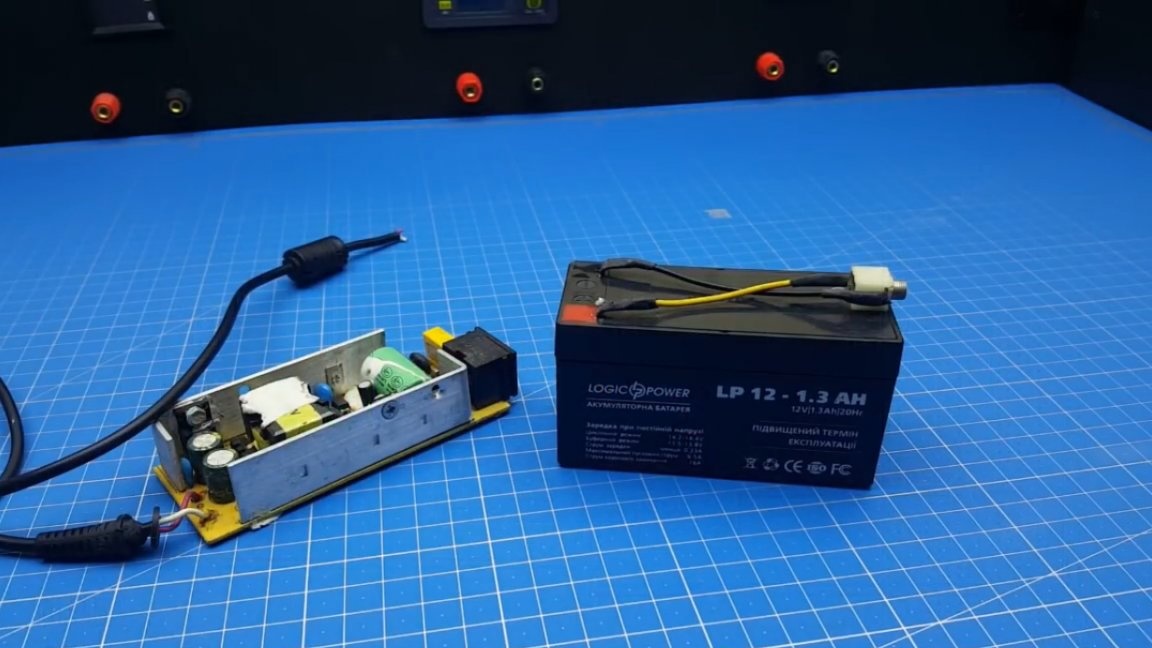
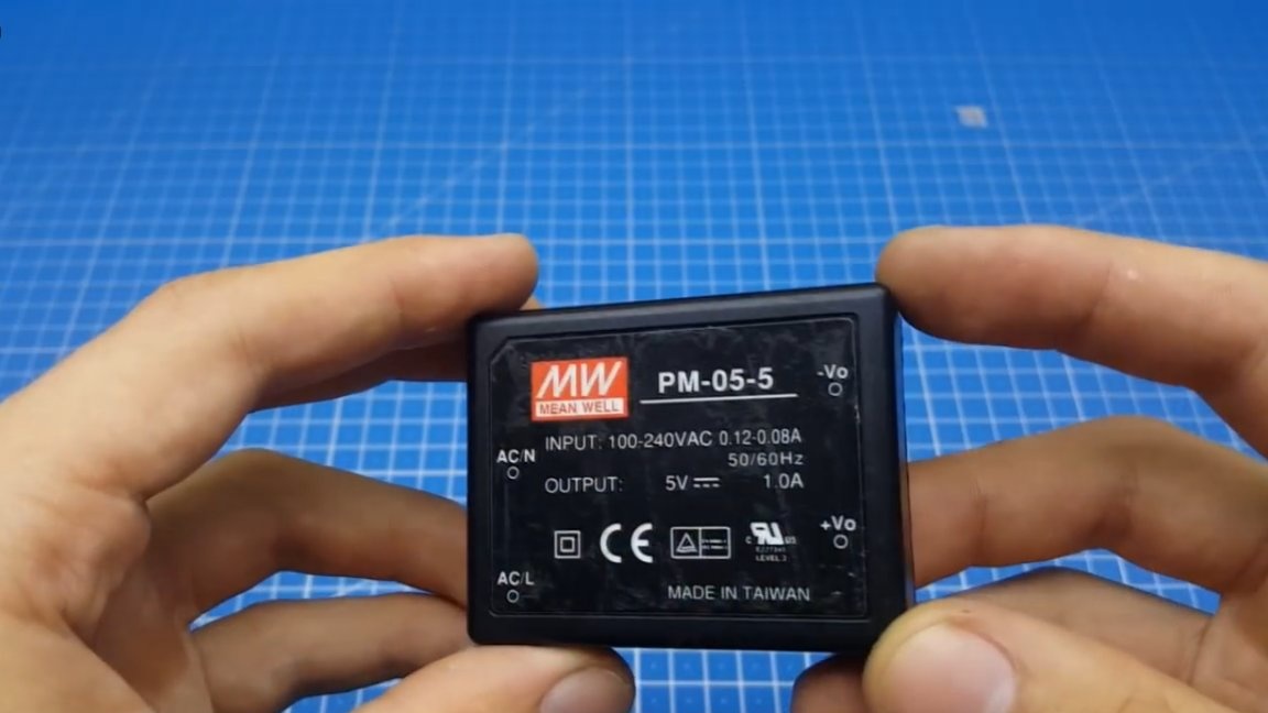
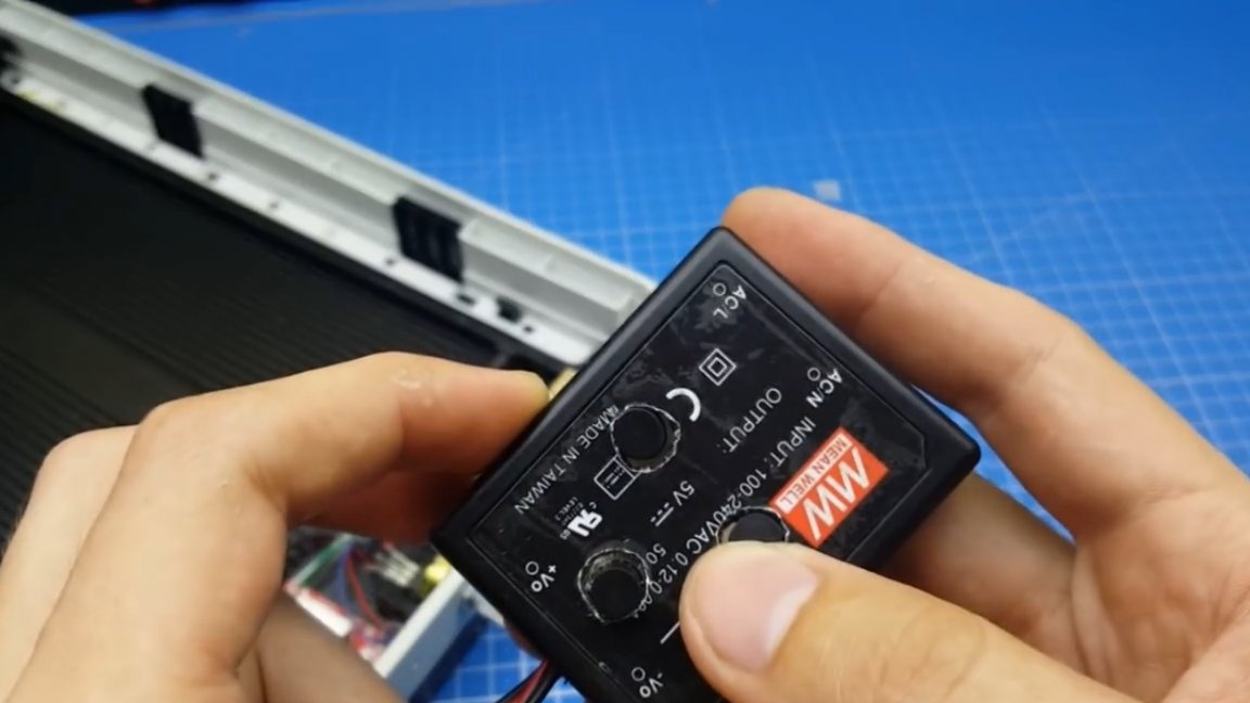
In order not to be bought by a bunch of batteries, which also need to be charged and their condition monitored, you can purchase this thing:
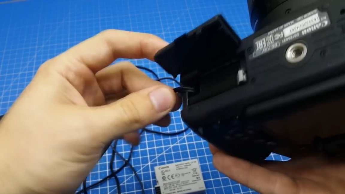
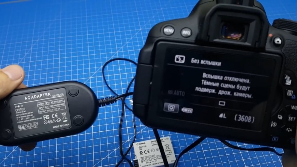
It is connected to a 220V network and allows you to shoot as long as you like. The only negative is that you will be “tied” to the outlet. But if you, like the author of today's homemade work, are mainly engaged in video shooting indoors (workshop / room /the garage), then in this case it is not critical.
Well, now let's go directly to our project - a makeshift slider from an old scanner. What is this generally a slider and why is it necessary, I think you have seen more than once. Top bloggers often use a slider to post the camera. Of course, wiring can often be done using a tripod, but this requires a difficult tripod, and with brake fluid, for a smoother movement. The slider allows you to shoot video with the same wiring, and there will be fewer jerks, or they will be completely absent, since the slider has an electric drive that can move photo / video equipment relative to the subject / objects with a constant speed.
You can use such a slider not only for wiring.If the camera is placed along the axis of movement of the slider, then you can zoom in and out on the subject.
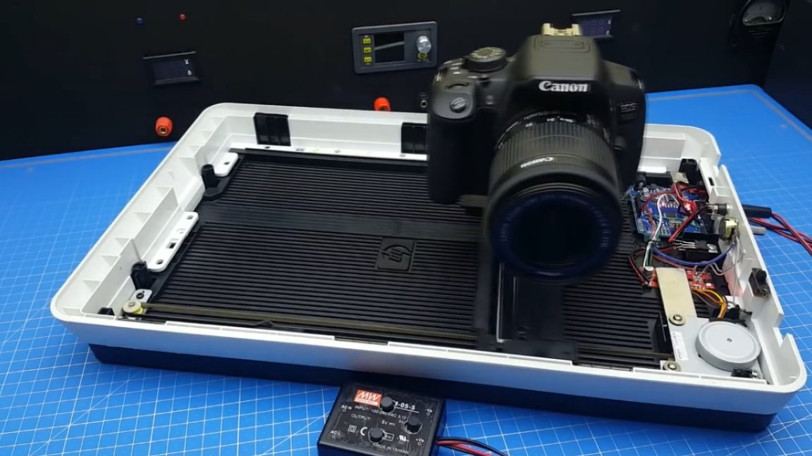
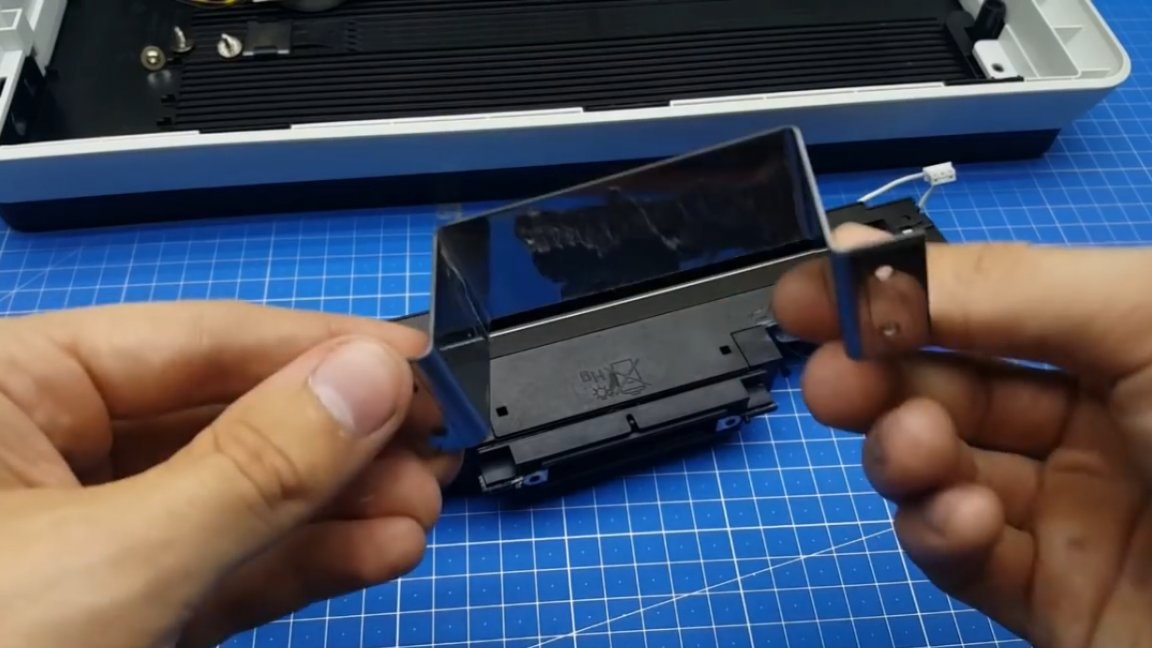
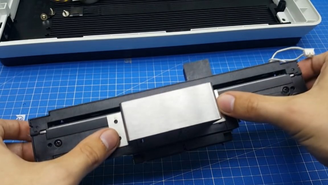
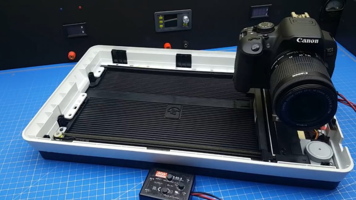
So, so how do you make this slider yourself? Yes, very easy! To do this, we need an old scanner or printer that has a similar movement mechanism.
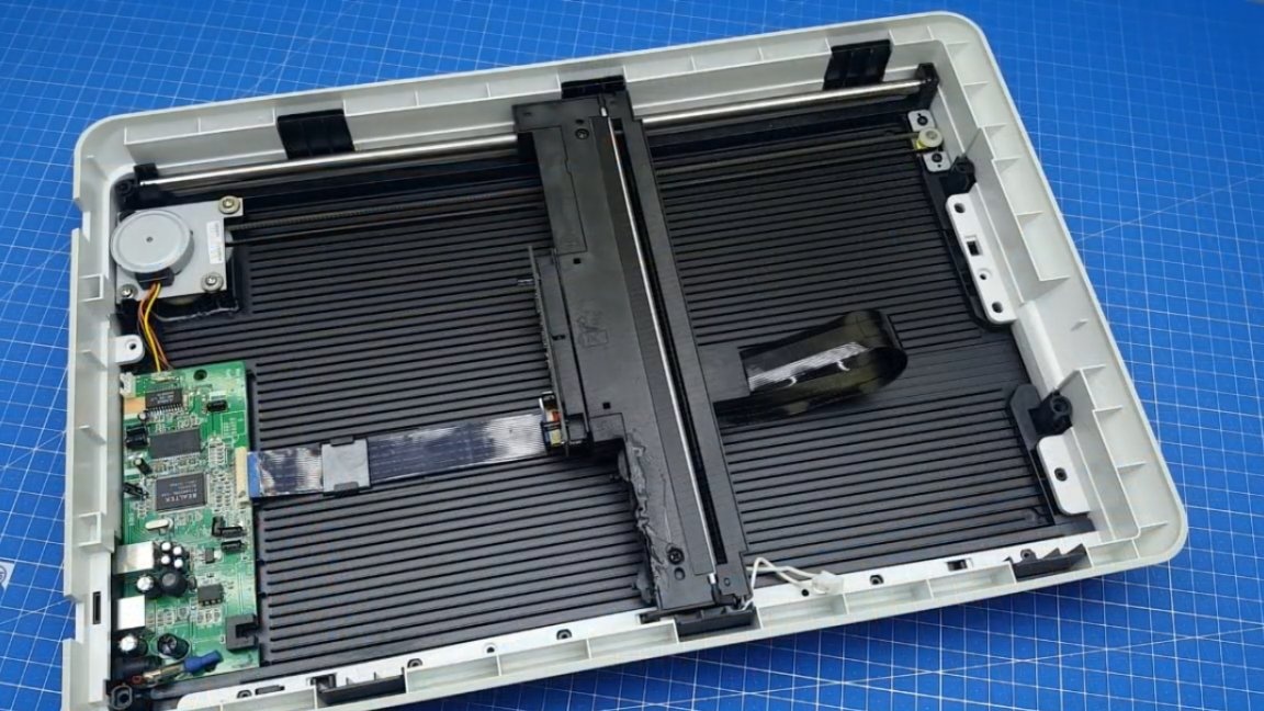
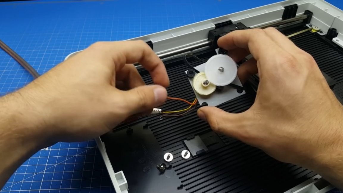
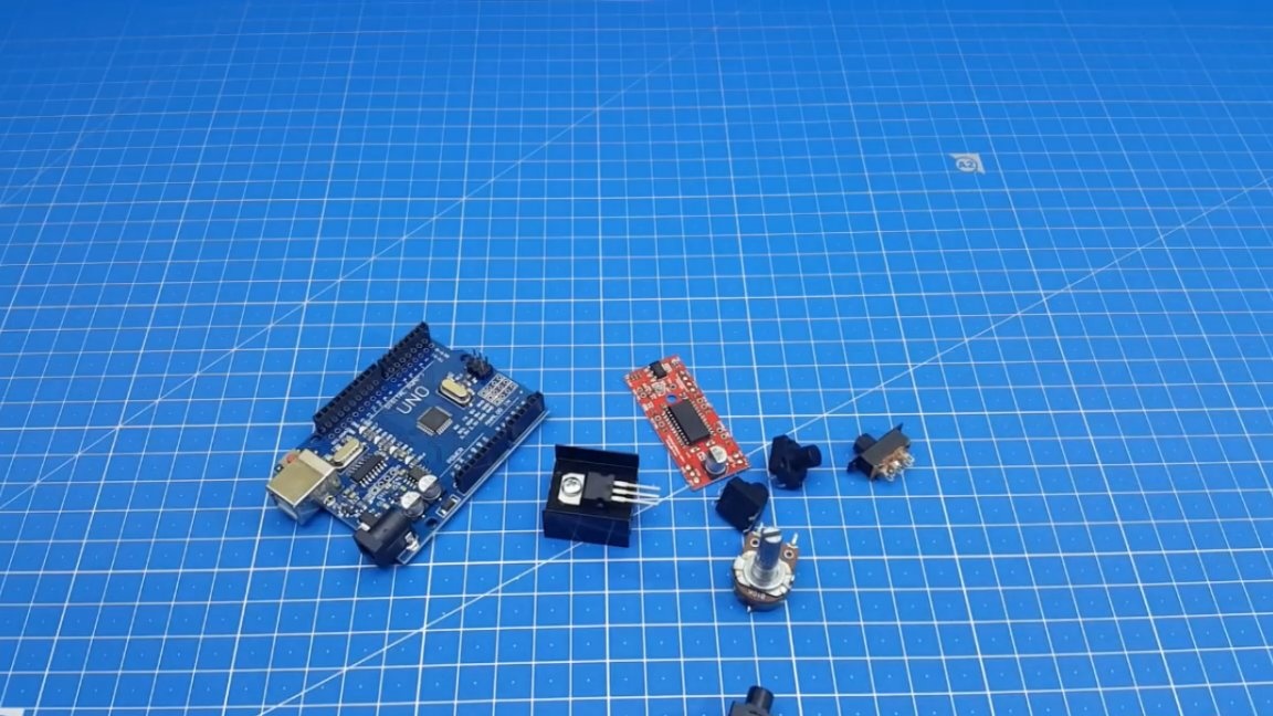
First of all, it is necessary to disassemble your old office equipment that has expired and remove all unnecessary spare parts. We extract the engine:
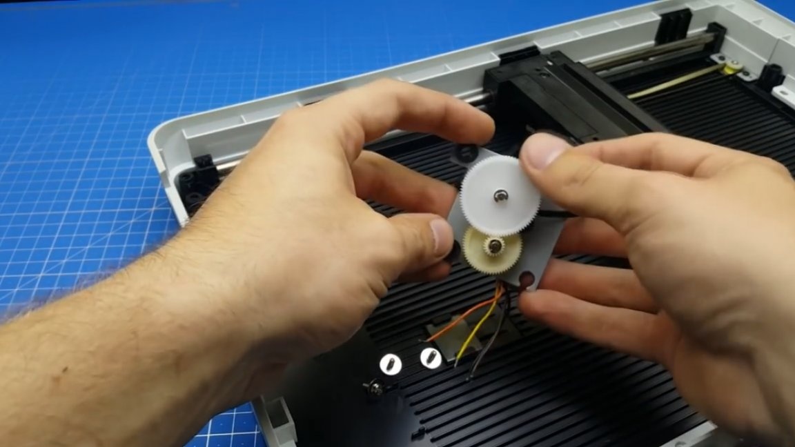
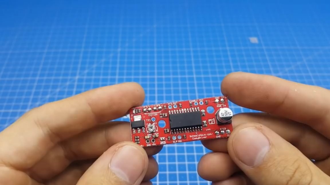
In this example, the drive was made on a stepper motor, which requires a special driver to start, if you just apply voltage to the motor terminals, then nothing will work and the movement will not happen.
On the market more often than others you can find models A3967 and A4988. Management in both cases occurs identically, so you can use both the first and second version of the driver.
Also, for the independent manufacture of the slider, we need Arduini Uno and a slightly different small things for the assembly of the control panel.
We pass link and download the firmware for arduino. There is nothing complicated, the author signed the main lines.
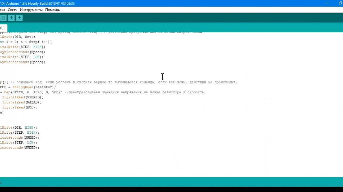
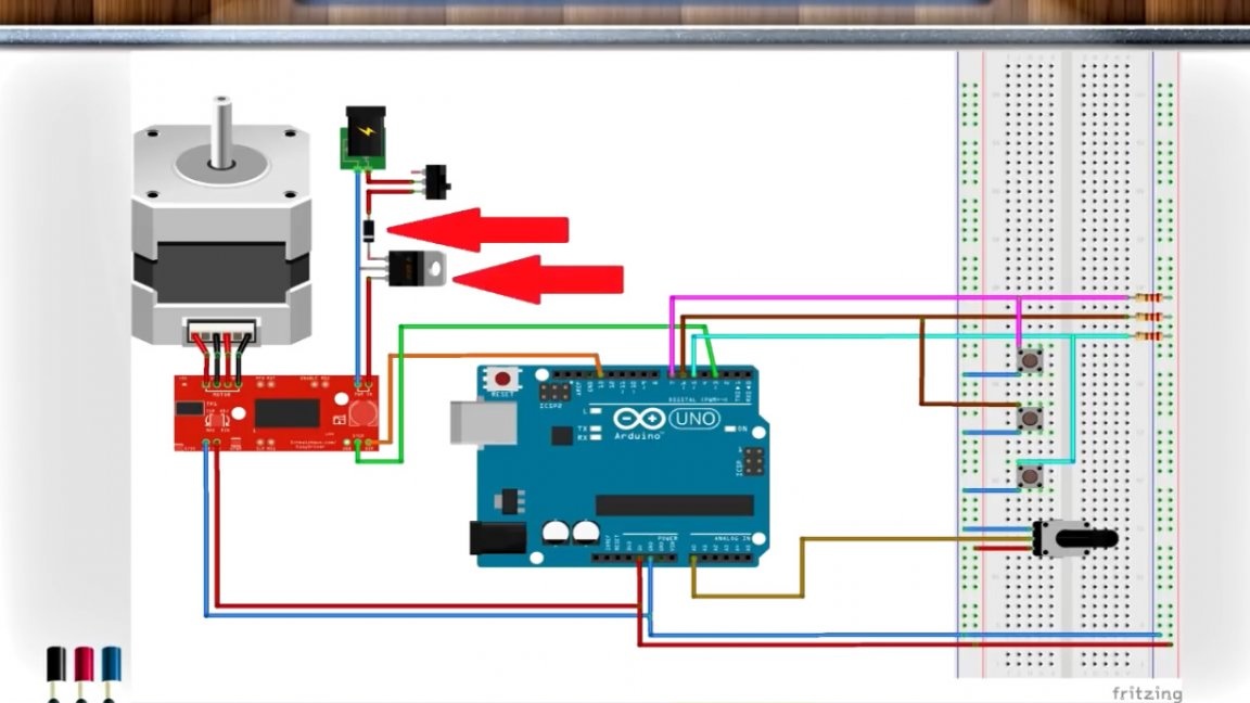
Fill the sketch and go to collect the scheme.
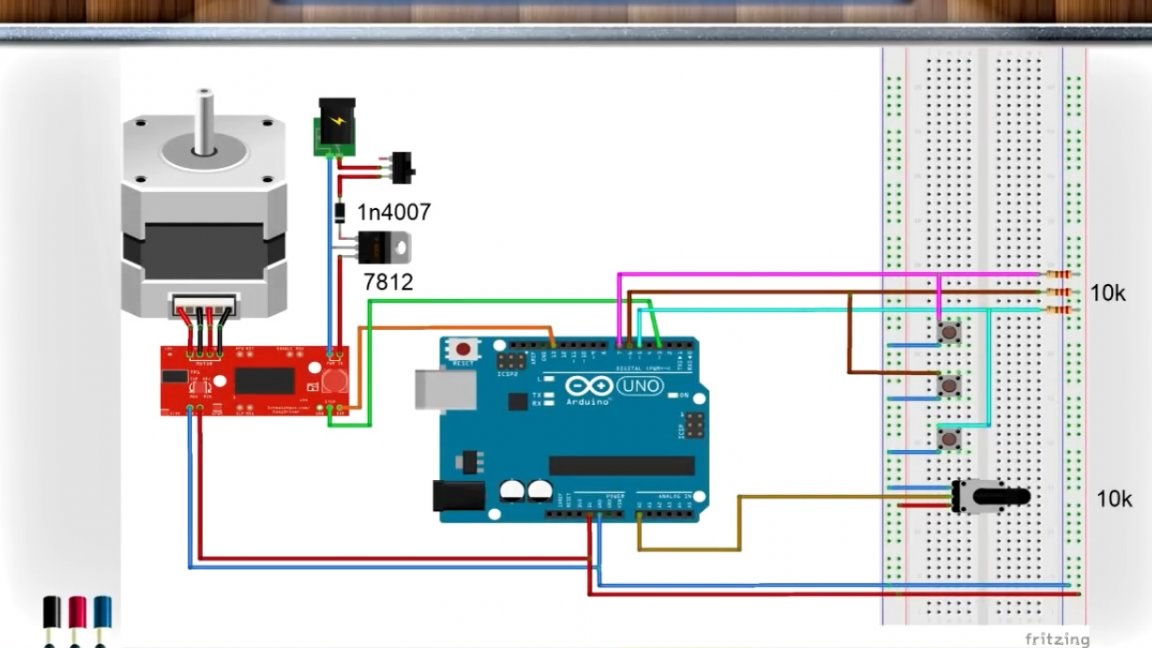
As you can see, the circuit is quite simple and is affordable for anyone, even a beginner radio amateur. As a power source, you can use a 12V power supply or batteries with the appropriate voltage.
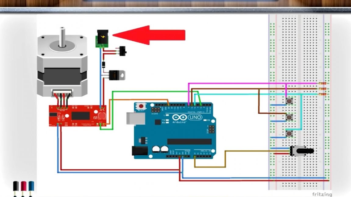
For extra security auto also installed protection "from the fool" and a voltage stabilizer 7812.
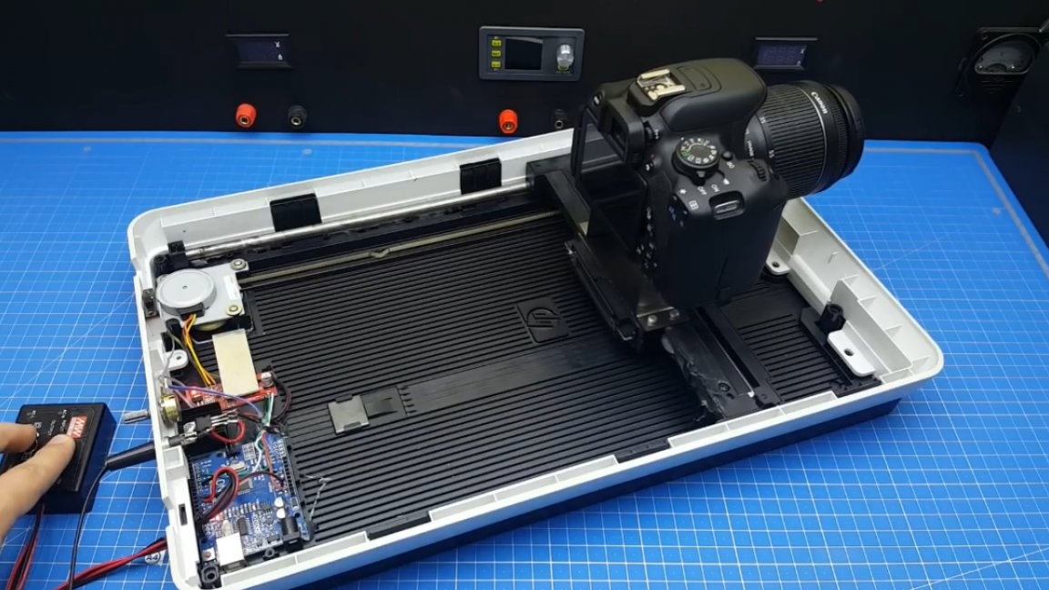
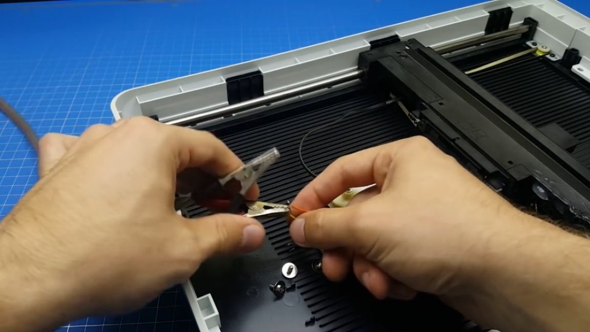
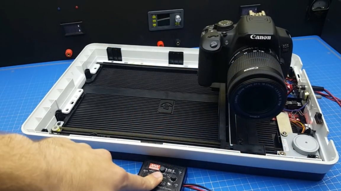
Assembly completed. Now let's check the result.
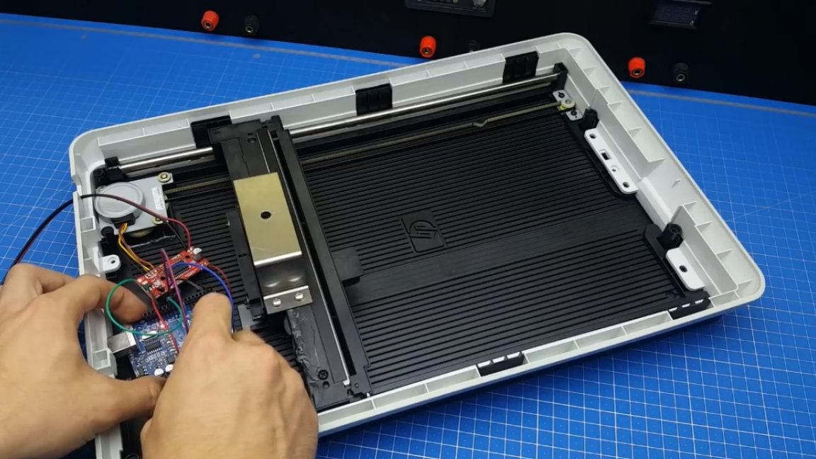
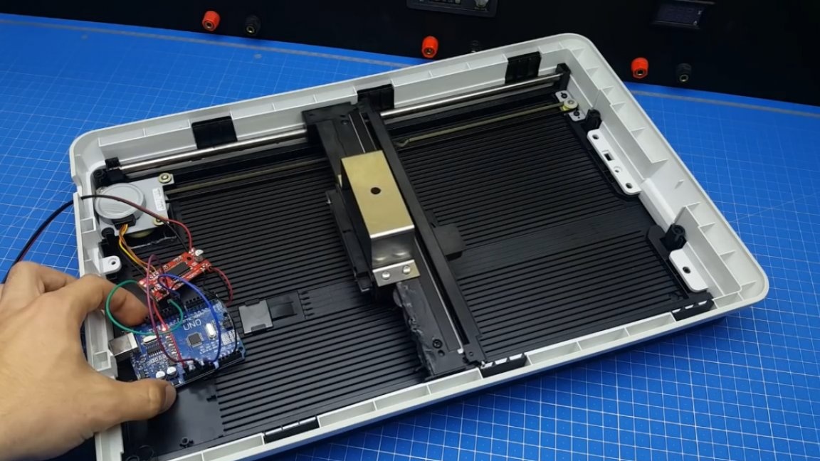
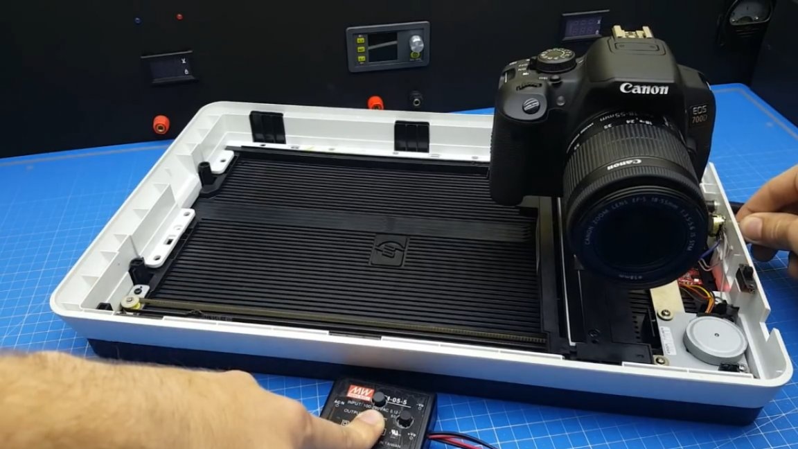
As you can see, the arduinka reacts and the device moves. Now it remains to neatly fix this whole thing. For the camera itself, the author made such a fastener:
It will allow you to further raise the camera and thereby remove the side of the scanner housing from the frame.
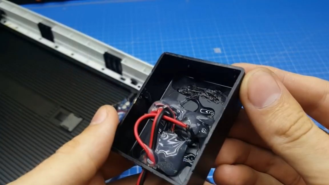
Now is the time to start making the control panel. Such a box from an old converter will serve as a body for it:
In plastic, you need to drill 3 holes and place the buttons. To fix the buttons we use hot melt adhesive.
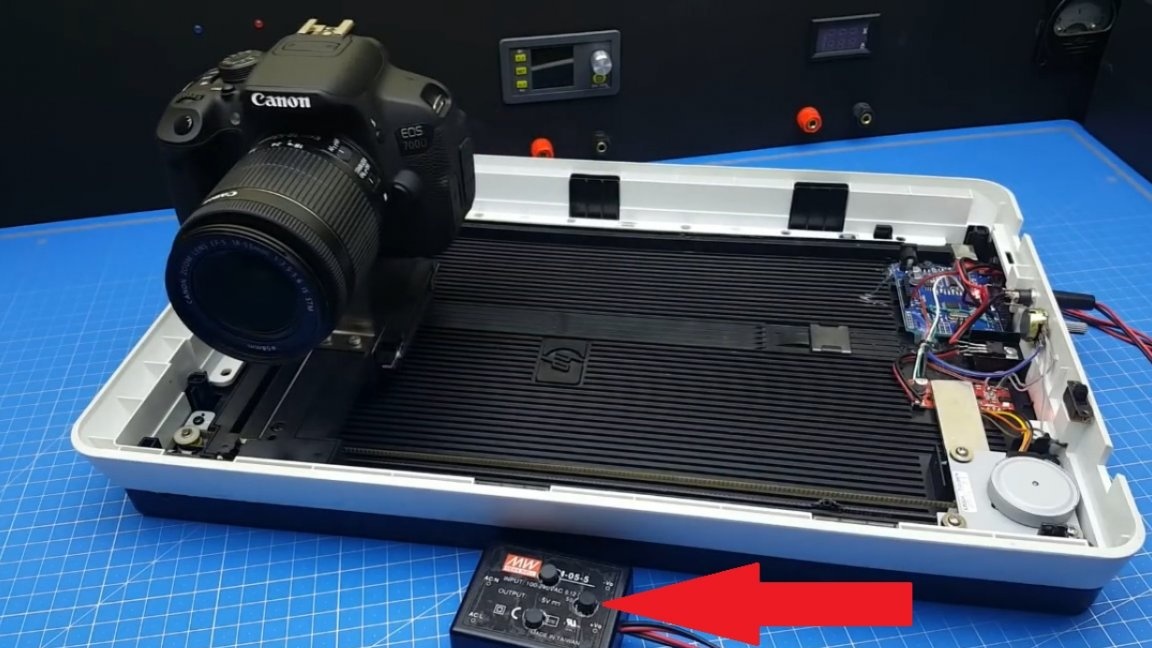
And now, our device is completely ready.
You can start the tests. More details in the author’s original video:
First we check the movement to the left, then to the right, and also see if the speed of movement changes by rotating the potentiometer.
Also in the code, the author programmed the movement by pressing the third key. If you press this button, the camera first goes one way to the limit, waits for a while, and then returns to the starting point.
This function is necessary to keep your hands free when shooting.
Here is such a homemade result. Thank you for attention. See you soon!