
Greetings the inhabitants of our site!
Analog measuring instruments are gradually being replaced by digital ones, but despite this, switch heads are still quite widespread, and not only masters of friends use them in their home-made designs. Of course, such devices are not famous for their super high accuracy, but nevertheless, in some measurements an analog device is simply irreplaceable.
In this article, we will consider in detail the manufacturing technology of a pointer voltmeter for a wide variety of tasks, literally for any voltage. Such a voltmeter can be used as a voltage meter in chargers, regulated power supplies, and so on. The author of this project is AKA KASYAN (YouTube channel AKA KASYAN).
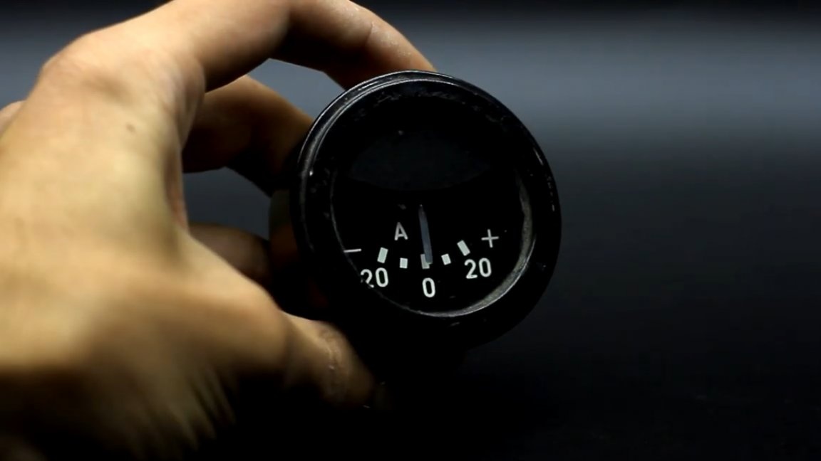
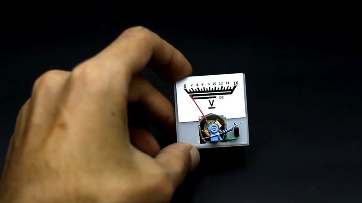
How to measure voltage, I think everyone is in the know. To begin with, we naturally need an electromagnetic measuring head.
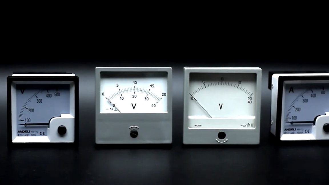
Such a head can be made do it yourself, but this process is not so simple, so a search is ready for an easier option. Literally any dial indicator of any size is suitable for this homemade product.
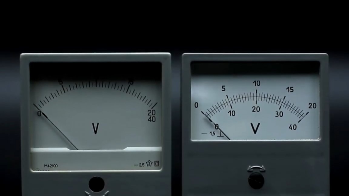
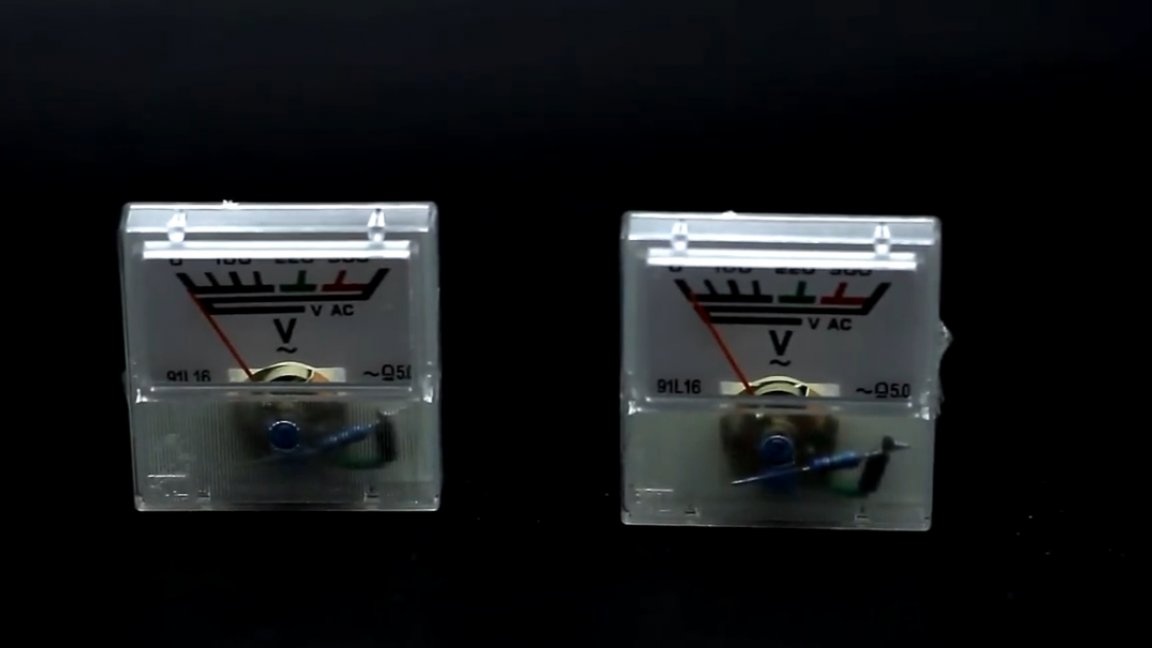
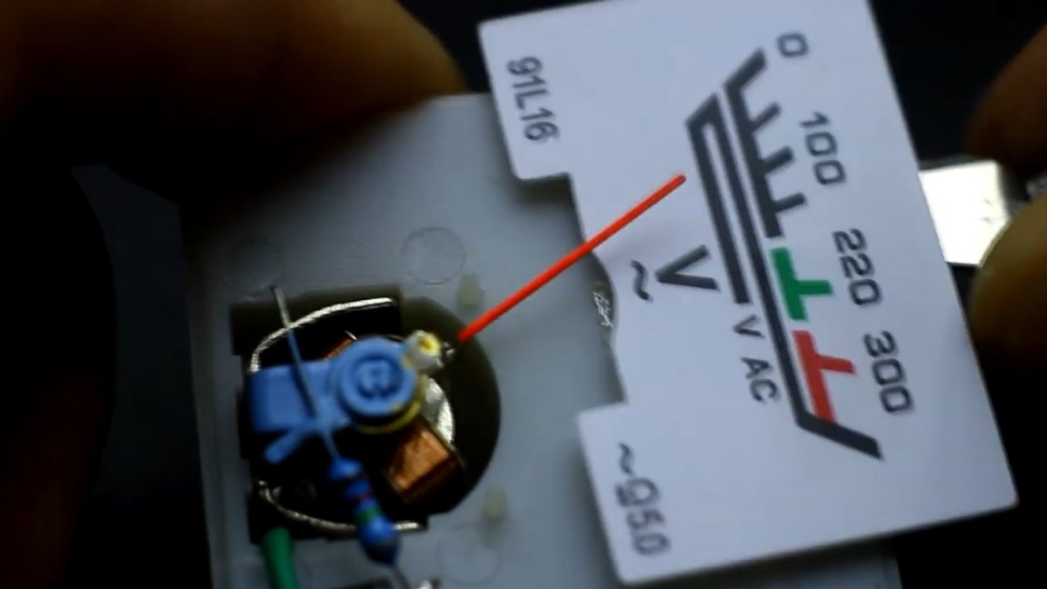
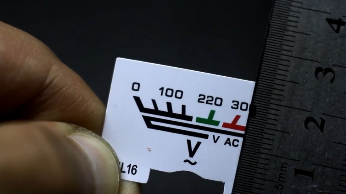
It is also desirable that the indicator has a linear measuring scale. In this example, the author used the head of a high-voltage AC voltmeter, which was safely removed from the stabilizer.
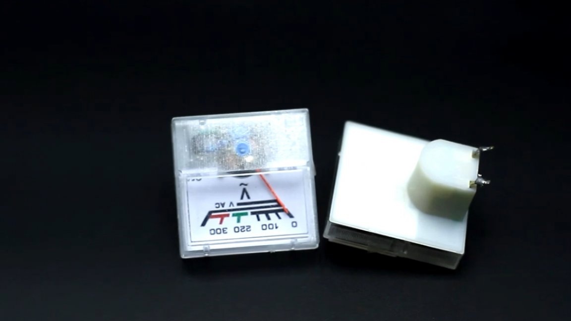
In this case, the author set the task of making a low-voltage DC voltmeter with a scale of 15-20 volts from a high-voltage voltmeter of alternating voltage. As you understand, this sample is designed to work in AC voltage circuits, and the scale is 300V.
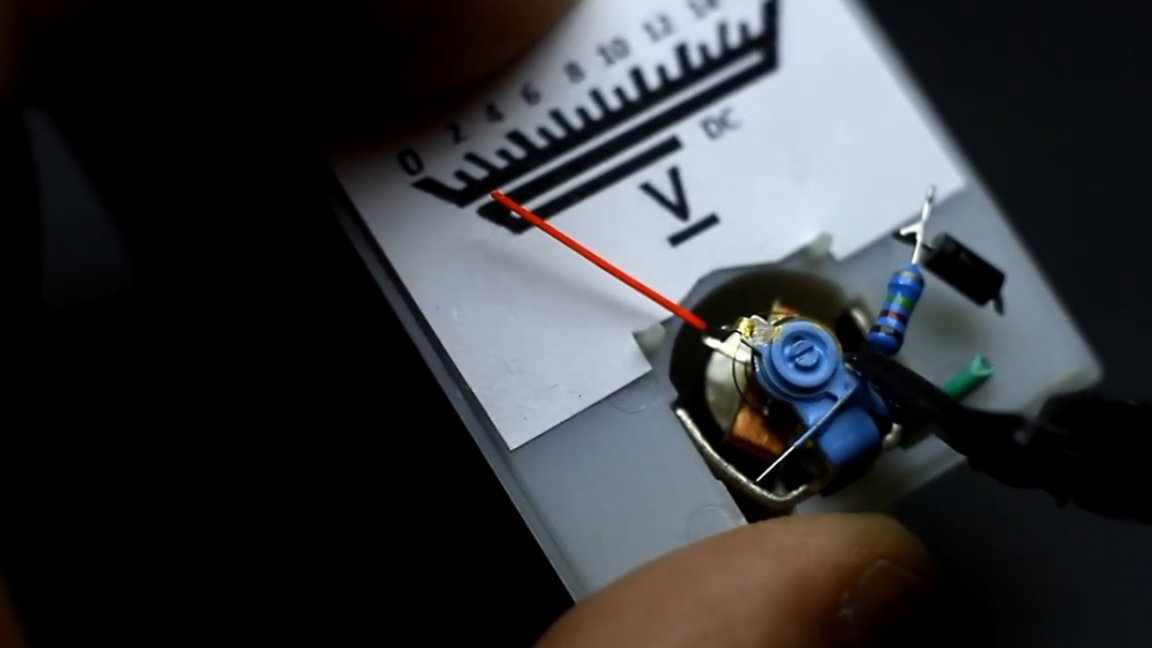
The first step is to open and disassemble the electromagnetic measuring head.
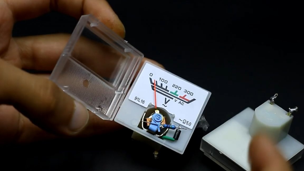
Inside we can see a rectifier diode and a current limiting resistor.
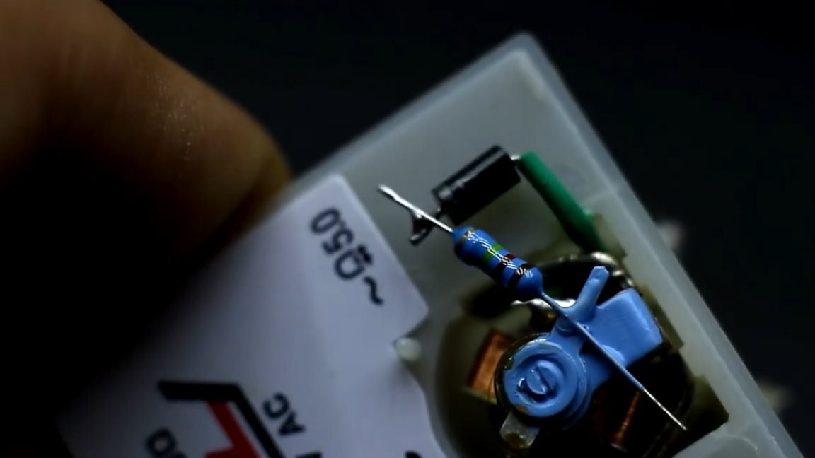
The voltage from the terminals of the voltmeter is fed to the winding of the measuring head through this chain of diode and resistor. We will get rid of them a little later, and now we carefully take out the scale, it is attached using double-sided tape.
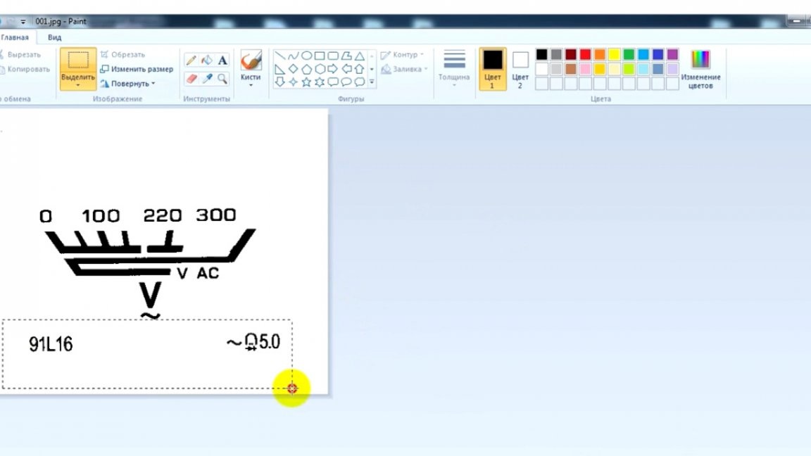
After that, the scale must be scanned.
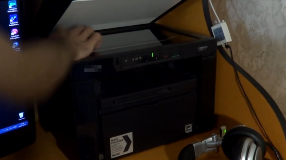
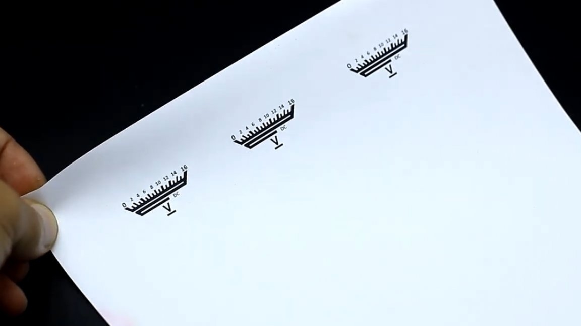
Further, the resulting figure must be edited. For this purpose, any editor is suitable, even the well-known “Paint” can easily cope with this task. We remove all defects, draw incomplete lines, symbols and inscriptions, and of course we change the numbers to the necessary ones.
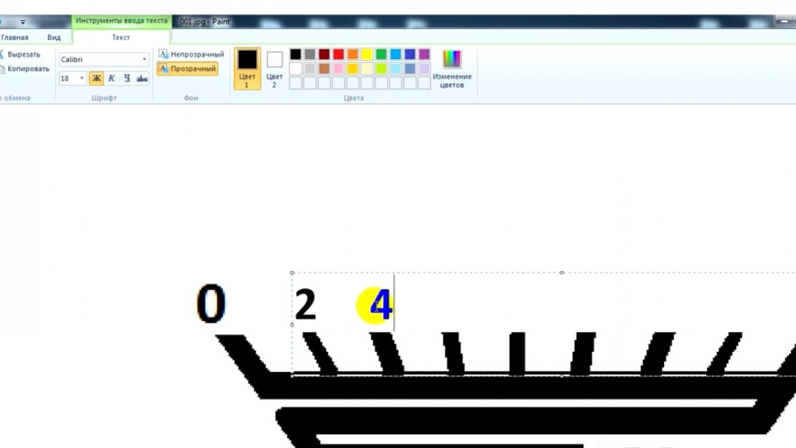
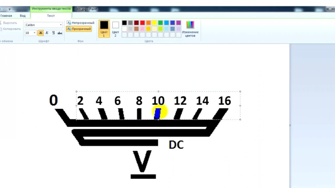
In this case, it was decided to make the scale at 16V.
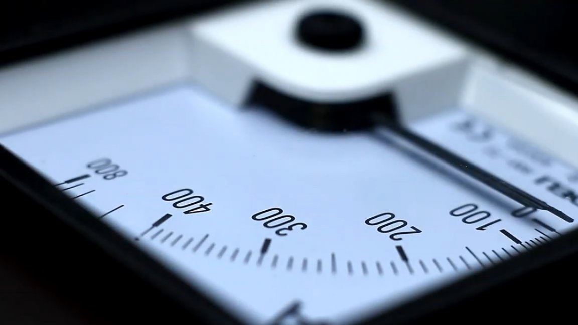
Then we take a ruler and measure the size of the native scale.
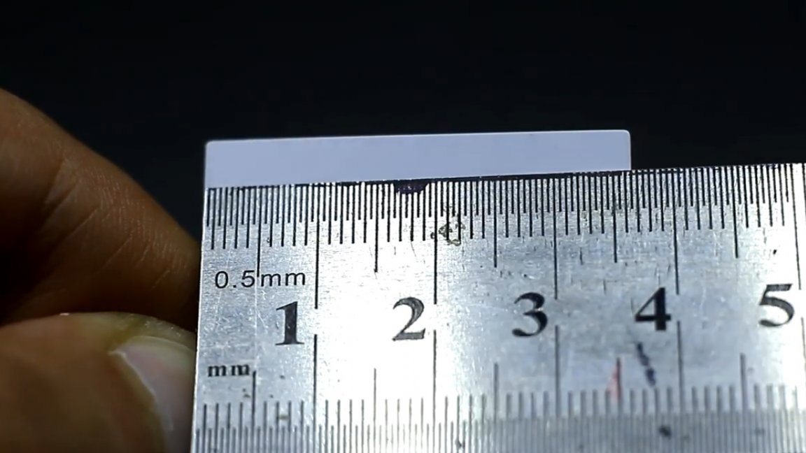
After that, open Word, insert our drawing there, indicate the sizes obtained, and of course we print out the whole thing, it’s better to have a few pieces at once, you never mind.


Now the paper must be cut to the desired size.
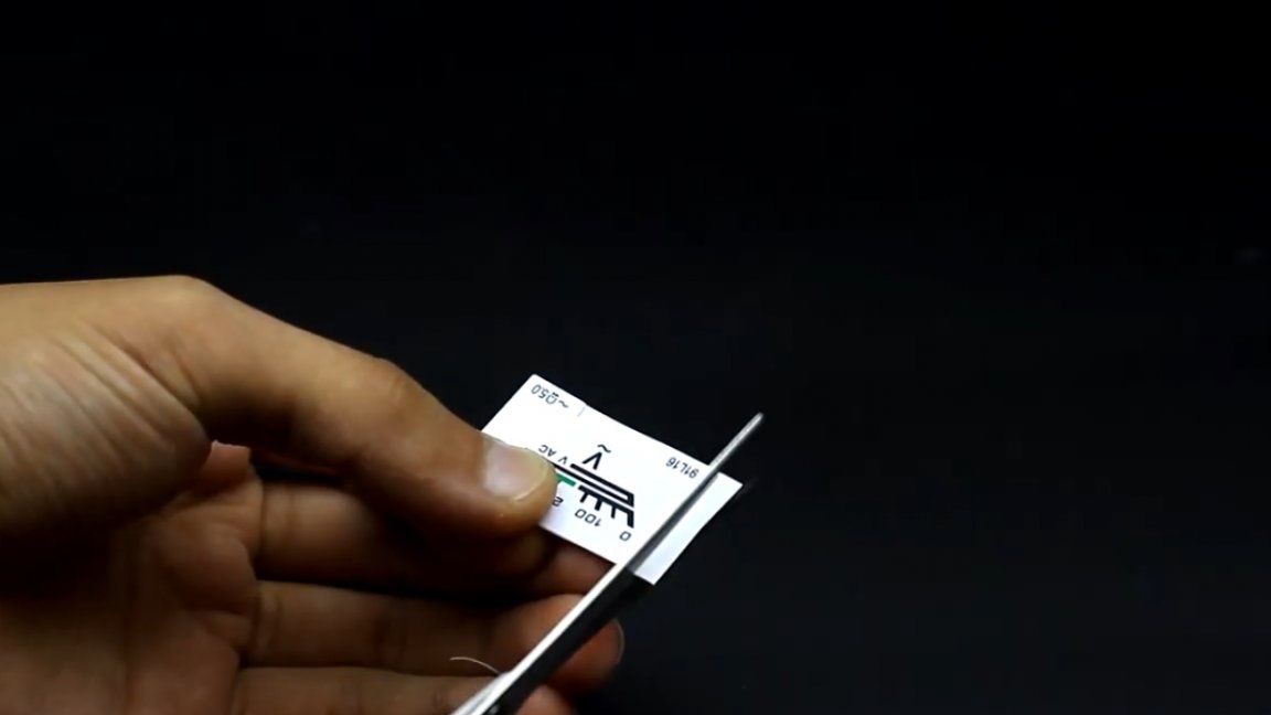
Then glue it into place with any improvised glue.
So, we sort of sorted it out, now gently bite the chain from the resistor and diode, which was mentioned at the beginning of the article.
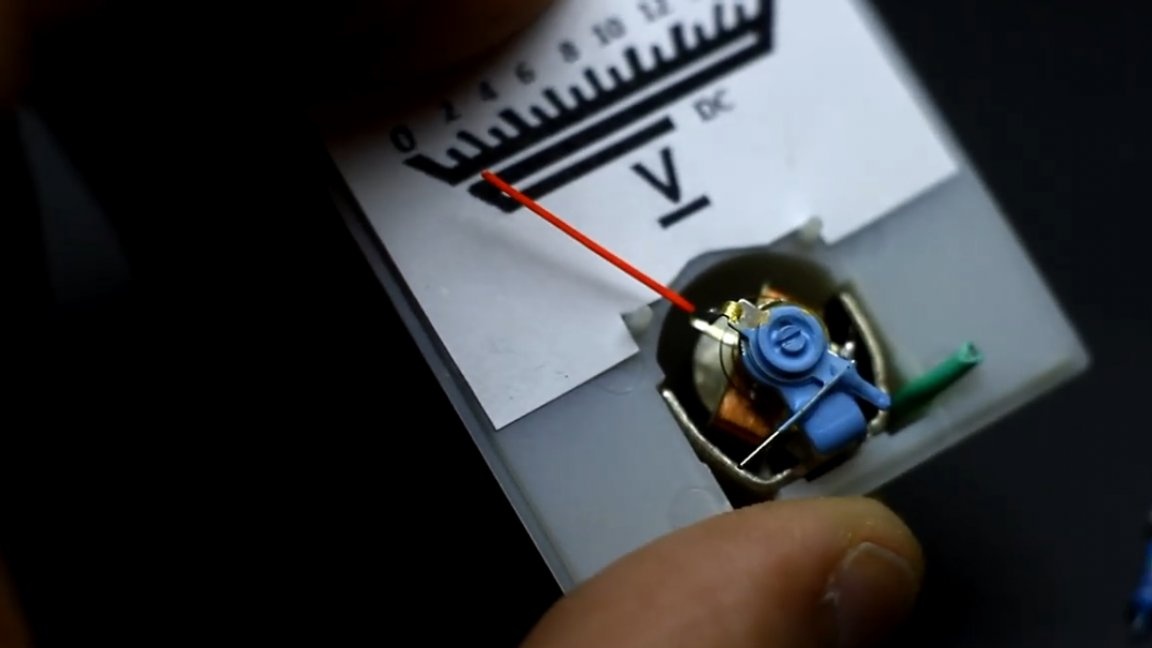
Now you need to solder the sticking conclusions to each other like this:
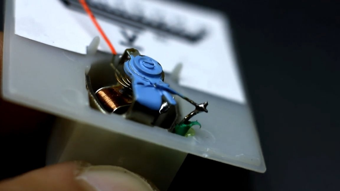
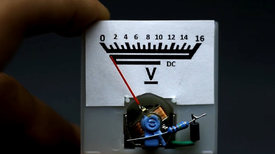
Thus, the voltage that we apply to the terminals of the voltmeter will directly go to the coil of the measuring head. This electromagnetic measuring head is quite sensitive, and the arrow is completely deflected if only 0.5V voltage is applied to the terminals.
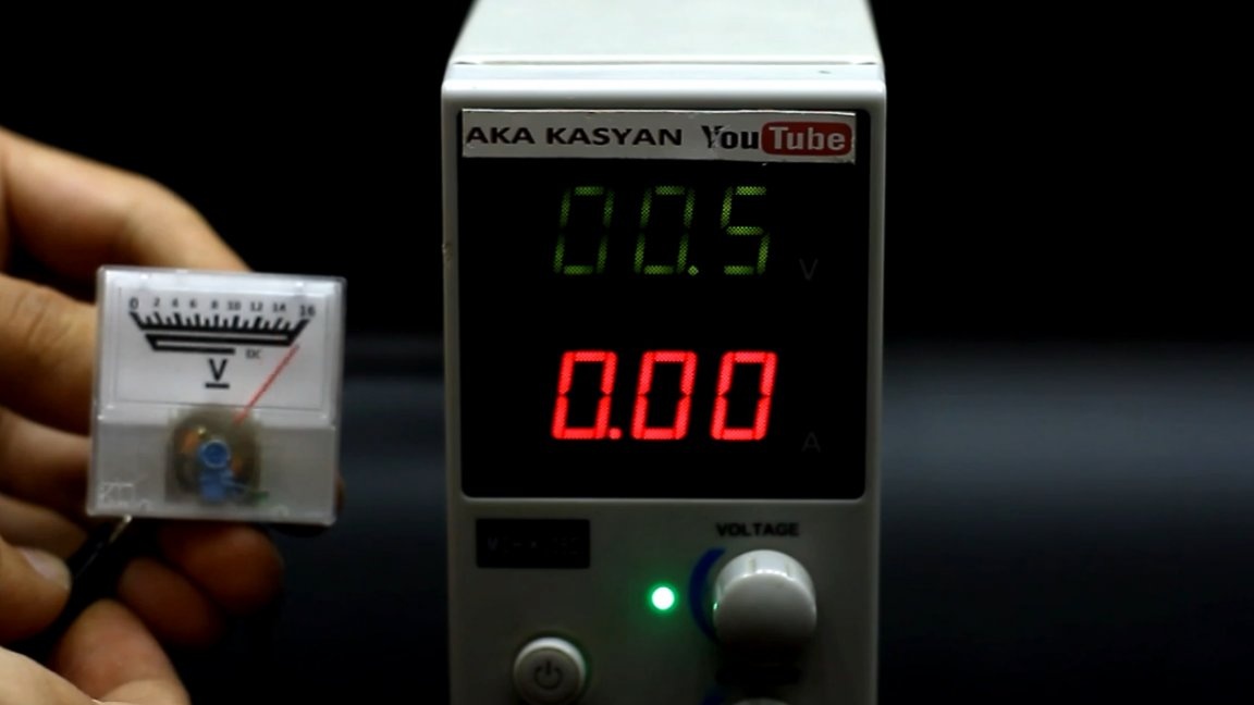
So it won’t work. This is no good, because according to our idea, the arrow of the device should deviate to the limit only if 16V voltage is applied to the terminals.
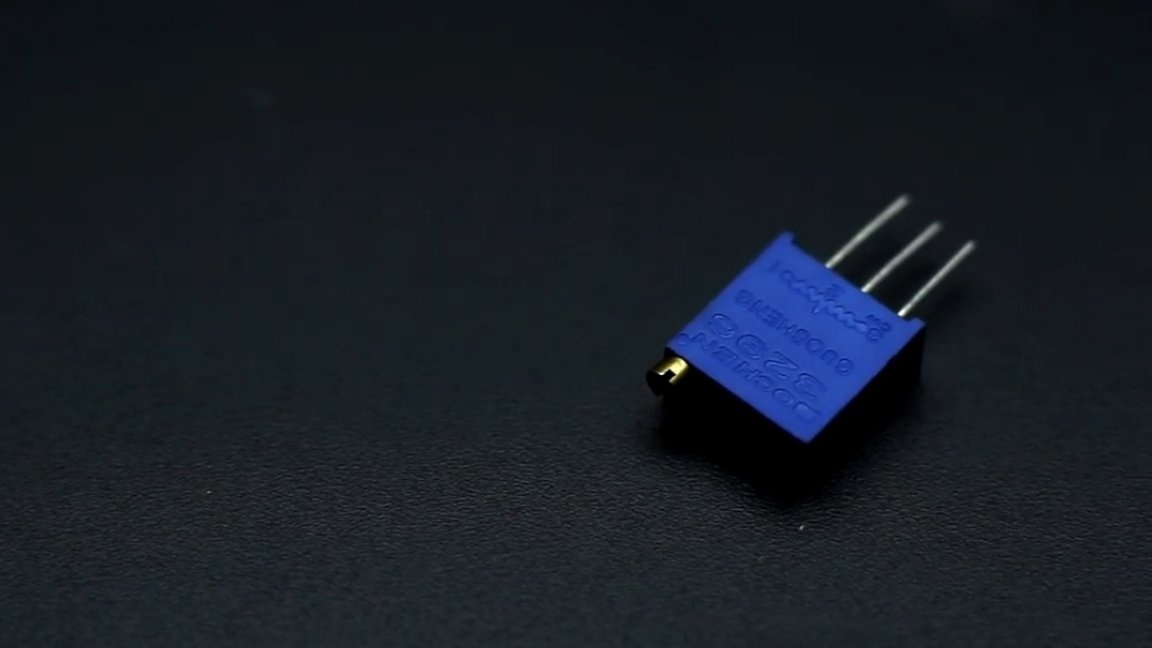
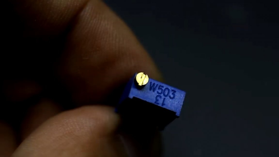
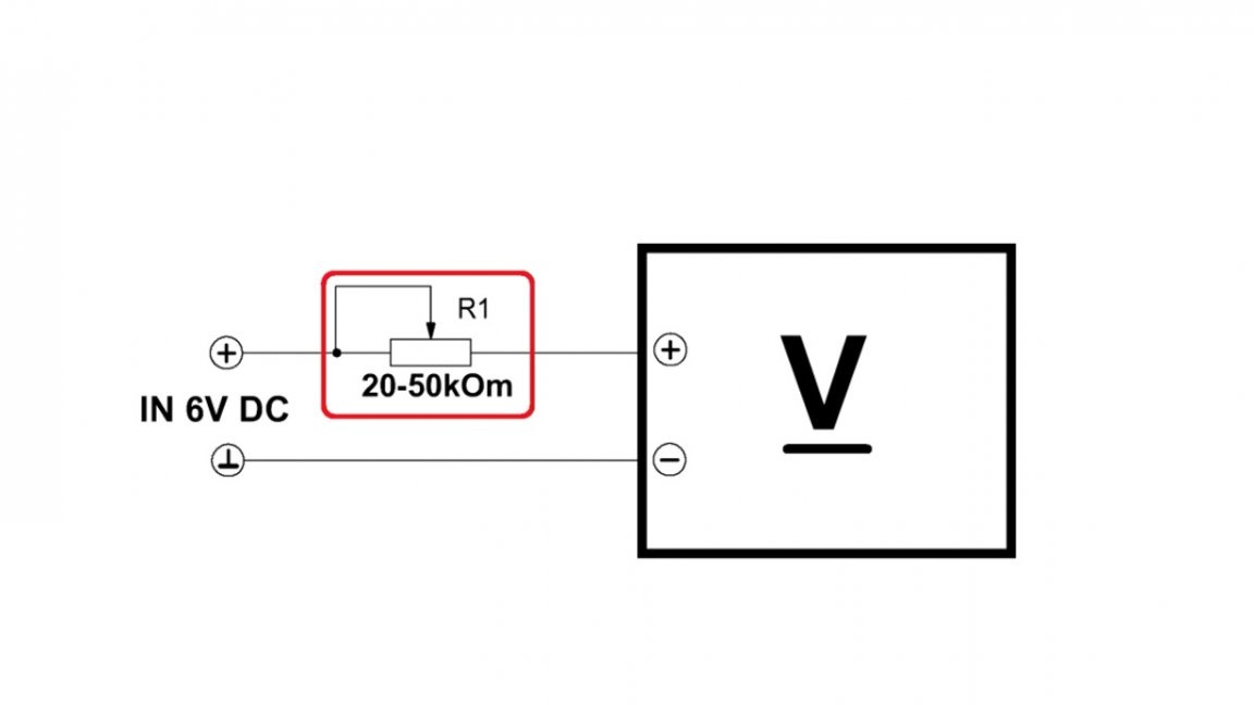
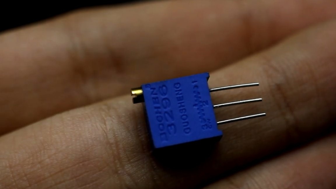
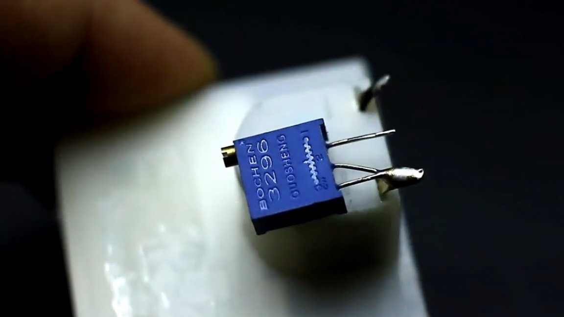
In order to fix this, we will need a variable, or better tuning, multi-turn resistor with a resistance of 20-50 kOhm.
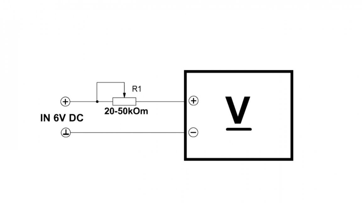
After which it is necessary to assemble such a simple scheme that is now in front of you:
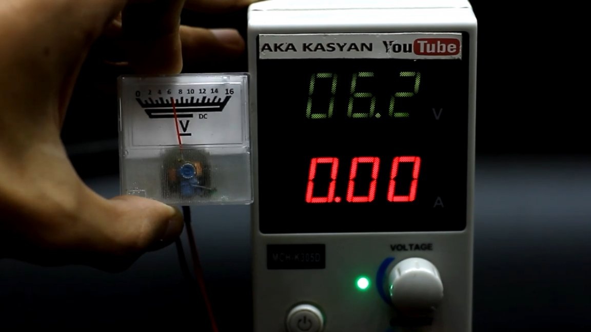
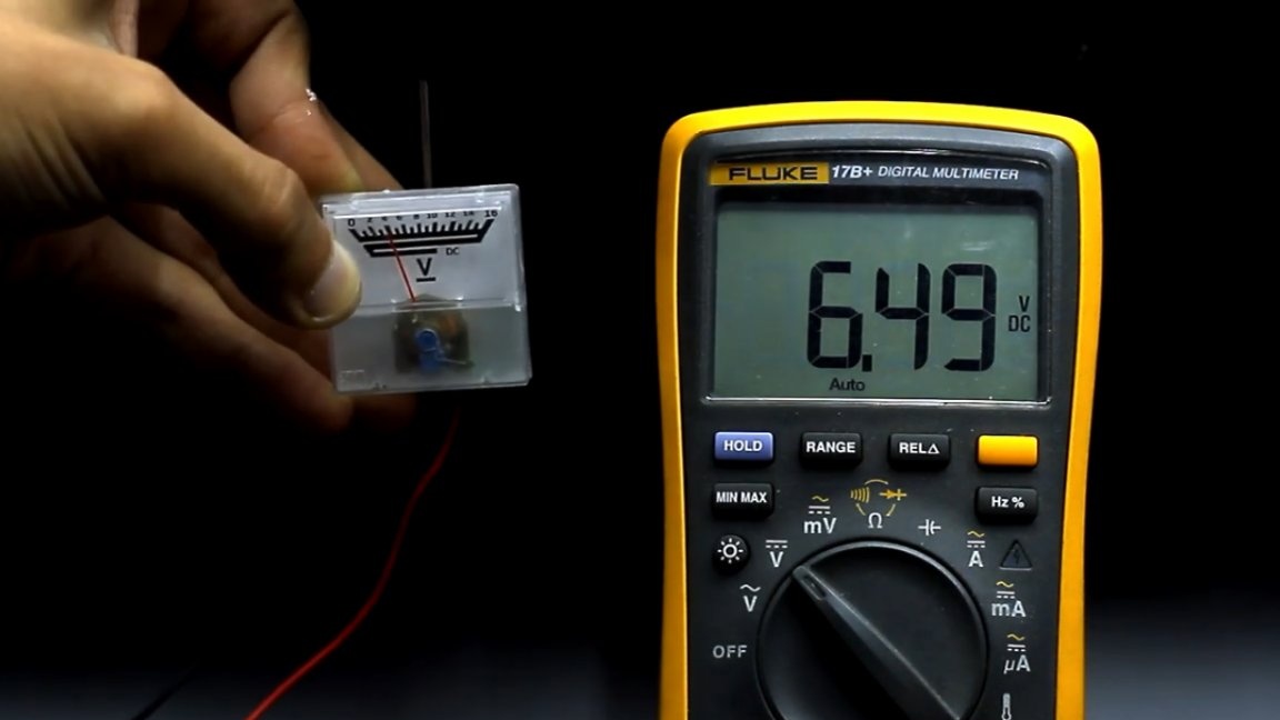
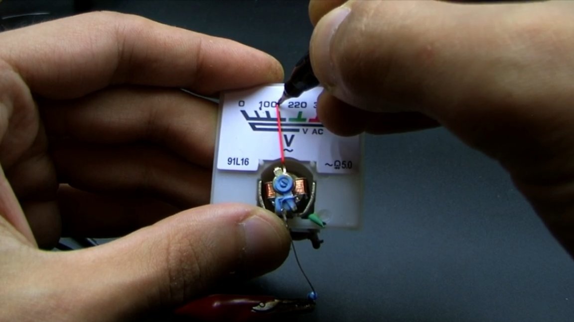
To calibrate the indicator, it is very desirable to have a laboratory power supply, but for lack of it it is quite possible to limit yourself to any power adapter of 6. Volt 6. Next, you need to connect a multimeter in parallel with the power supply, we will use it as a reference.
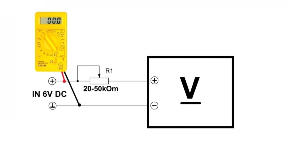
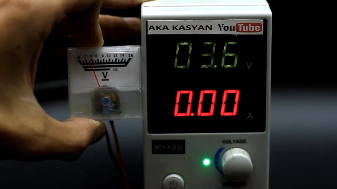
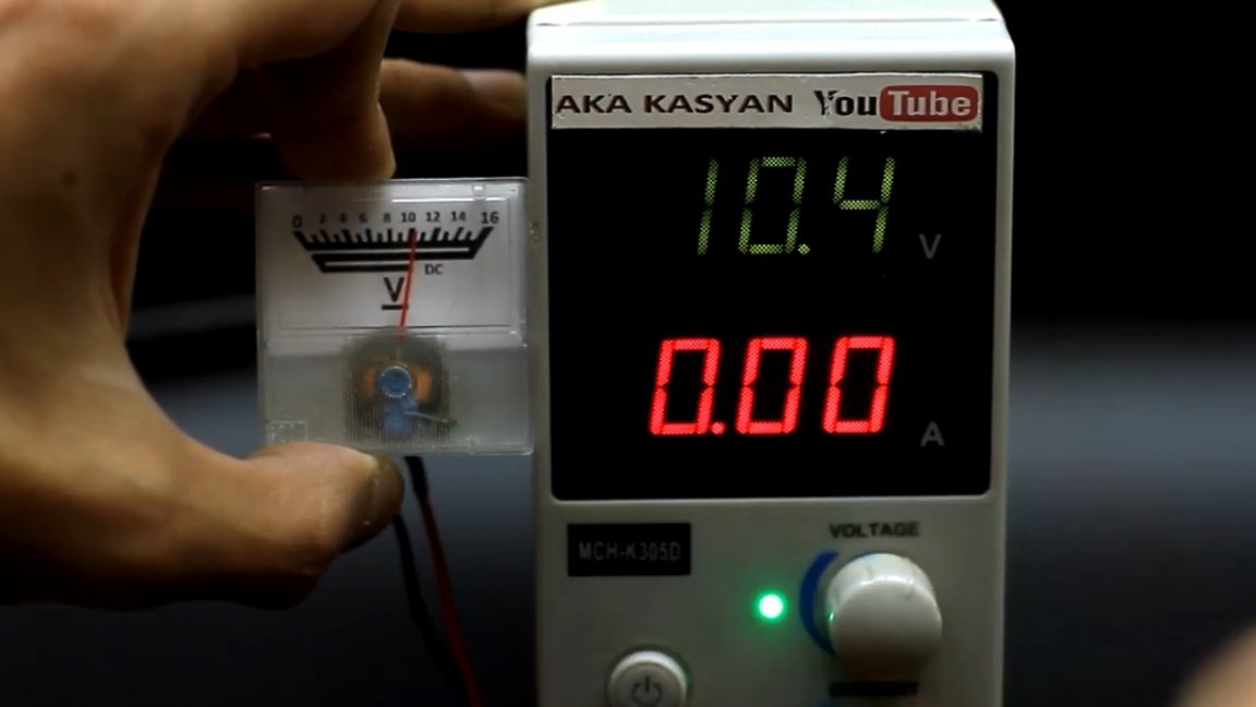
Now we apply voltage to the input and slowly rotate the tuning resistor until the arrow shows the voltage that we see on the multimeter.
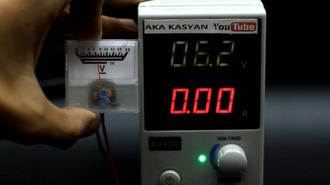
That is, it is enough just to calibrate the head at a specific mark, and due to the fact that the scale is linear, our meter will also adequately show the other voltage values.

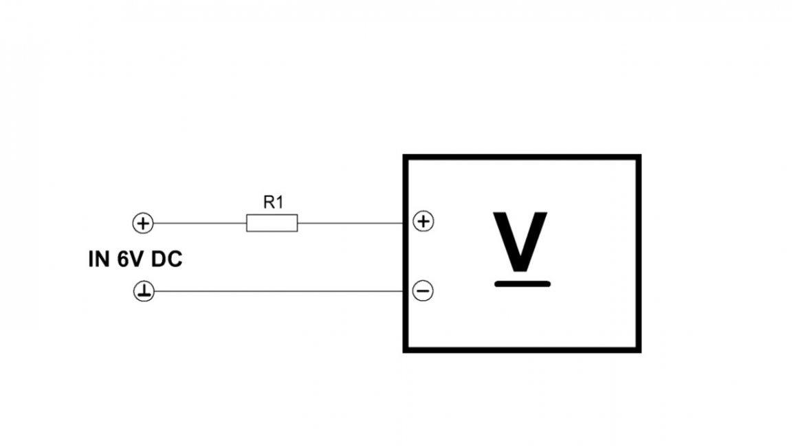
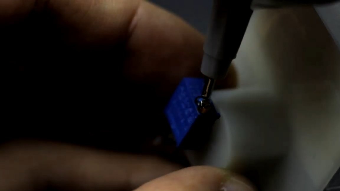
After the calibration is completed, the trimmer must be removed.
Next, it is necessary to measure the obtained resistance, and in place of the soldered trimming resistor we install a constant resistor with the same resistance.
If you do not have the necessary resistor at hand, then you can connect several resistors in series to obtain the desired resistance value.
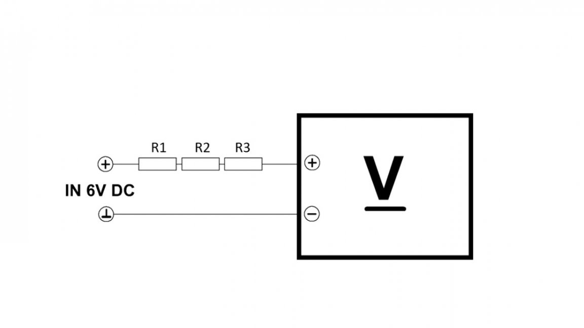
For this project, it is desirable to use resistors with an error of 1 or less percent.

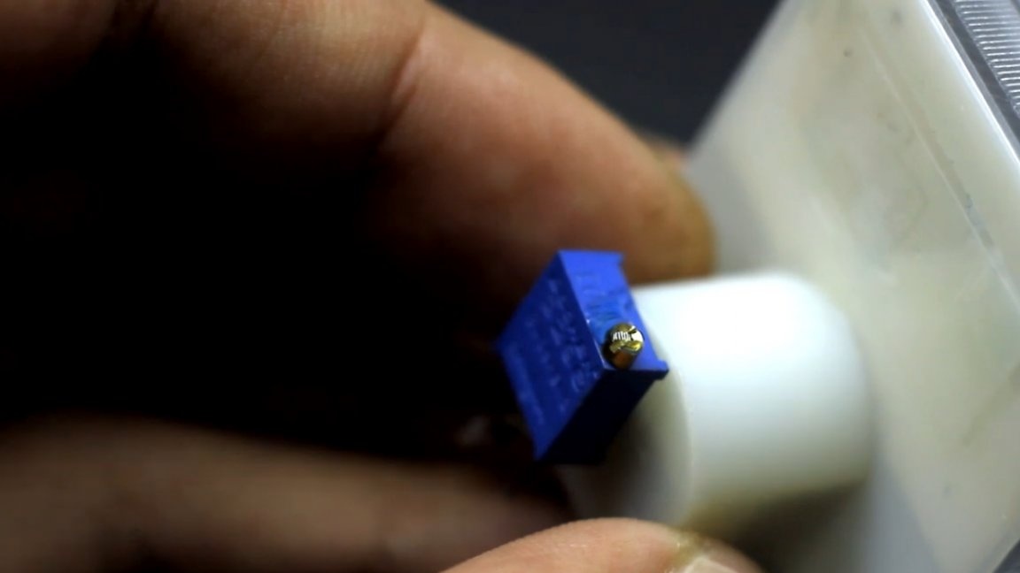
The trimmer can of course be left, but before that it will be necessary to glue the adjusting screw to prevent its displacement.
Very often for construction and measuring heads, at the very beginning, through the restrictive resistance, the reference voltage falls on the head and marks are made on an empty scale that are taken into account when creating the scale in the editor. This approach is preferable, as it allows the construction of measuring heads of fairly high accuracy.
And that’s all. Thank you for attention. See you soon!
Author's video: