

Laboratory power supply - an essential device in an amateur workshop, in electrical practice. The author does not conduct regular work with thin and delicate electronics, but sometimes it is necessary. And when the device is ready, the search begins for suitable CREN and LM ("walking" village network). Recently, one also has to deal regularly with LED strips (built-in backlight). LED strip in such lamps is often used in a rather bizarre manner and as a result of this kind of installation work, more than one regular switching power supply unit was damaged. In short, the need has ripened.
Technical task
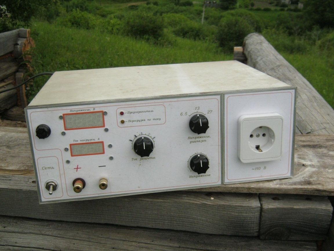
The power supply was seen as linear (low-frequency transformer) as more tenacious, simple and maintainable. The weight and dimensions for a stationary appliance are not very important. The power supply must be adjustable, to produce a constant stabilized voltage up to, say +20 V, with a load current of up to several amperes. The power supply must certainly be equipped with short circuit protection, and an adjustable protection against overload current is also desirable. The power supply can be single-channel, unipolar.
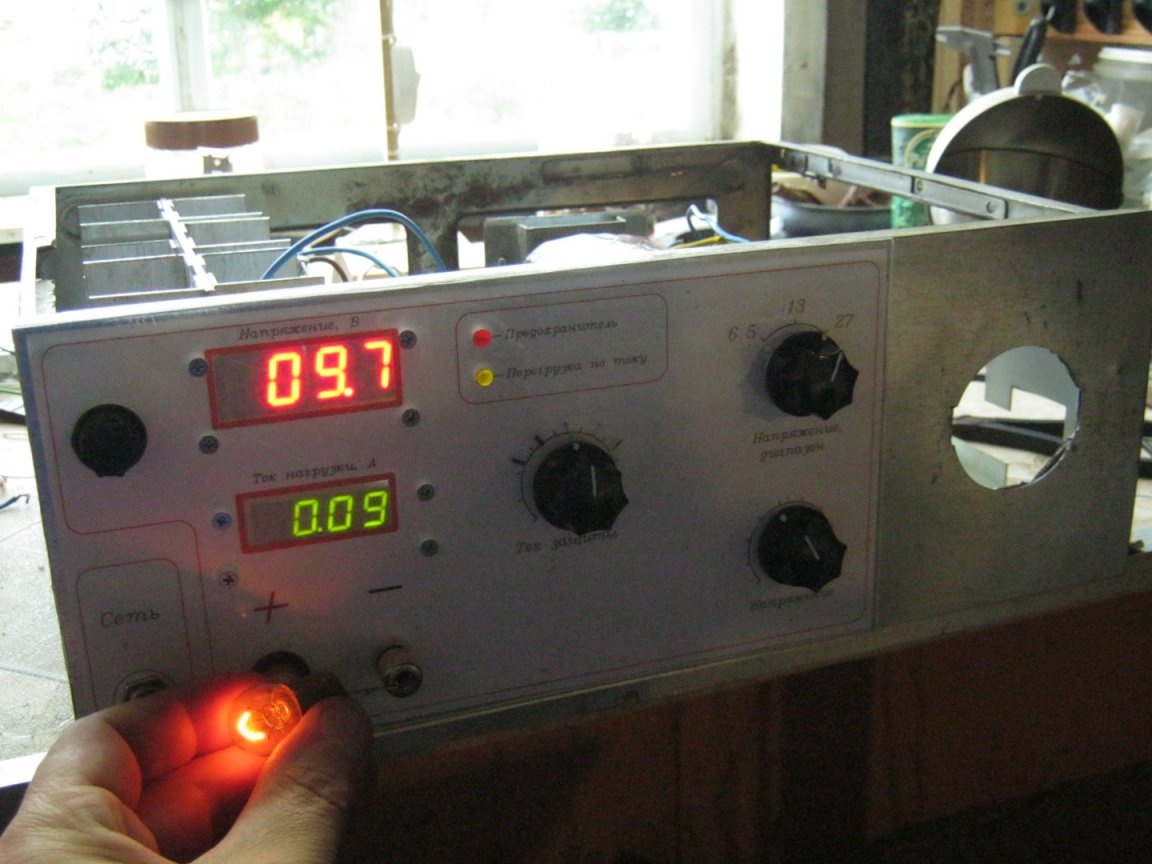
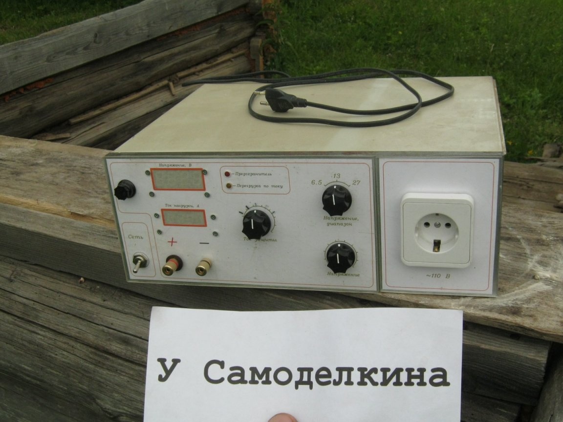
It is very good to have “on board” a set of measuring instruments - a voltmeter-ammeter. This greatly increases the convenience in work, will allow for some other work and measurements, frees up the working space on the table from unnecessary external devices and wires.
The manufacture of designer lighting fixtures implies the likelihood of their sale, including to countries whose electric networks. Fortunately, pulsed power supplies have an input voltage range that covers all possible values - ~ 100 ... 240 V. It remains only to supply the network adapter with a suitable adapter. Mains voltage close to 240 volts is not uncommon in our network (on one of the phases). The lower value of the range is nowhere to take. It is highly desirable to check the operation of the PSU at low voltage, given the quality of most Chinese-made power supplies that come to us. The TS-180-2 power transformer used in the laboratory power supply unit has network windings on two coils (divided into two equal parts). This made it very easy to obtain the desired voltage of ~ 110 V.
What was needed for work
A set of tools for electrical installation, a multimeter, a soldering iron with accessories, a set of metalwork tools.
In addition to radio elements, a case from an old PC-shnik, a piece of plexiglass, a bit of roofing steel, thick PCB and aluminum went into business. KPT-8 paste, fasteners, mounting wire and copper wire, thermotube, nylon straps, paintwork materials.
Construction
It was decided to assemble the power supply on the basis of a specialized microchip of the adjustable stabilizer KR142EN12 (LM317). This made it possible to obtain quite decent parameters with a very simple device circuit.
The circuit has the following features - switchable (switch SA2) secondary winding of the transformer TV1 to reduce the heating of the regulating element of the stabilizer. The amplification of the stabilizer chip DA1 remote transistor VT1. Microcircuit protection actuation current regulator on elements R5 ... R9, SA3.
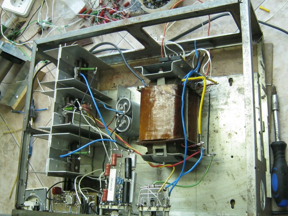
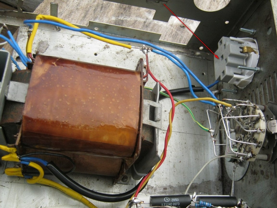
Mains transformer - TS180-2 with rewound secondary windings. In addition to the power secondary windings, two relatively low-current windings for bipolar power stabilizers of measuring instruments were wound. Transformer coils are varnished, which made it possible to minimize its acoustic noise (buzz) and allowed us to hope for long-term work with the old winding wire.
The power supply unit uses home-made measuring instruments - a digital voltmeter and an ammeter on the KR572PV2 microcircuits (ICL7107) [3]. Seven-segment indicators, for the convenience of quick recognition, of different sizes and different colors. Instrument circuits require bipolar power supply +5 V, -5 V. Each device requires its own power supply, the ammeter power supply must be completely isolated from the main circuit.
The contacts of the switches SA2, SA3 must pass current up to 3A. As these switches, biscuit PGCs [2] with ceramic boards were used. The permissible current through the contact group is 3 A. To increase the reliability of the power supply, the contacts of synchronously working groups are connected in parallel.
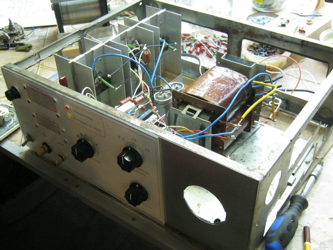
The power supply is assembled in an old iron case from the PC system unit on the 80286 processor. It is also without radiators and blowing fans. The case is small in size, made of steel of considerable thickness. It is a welded box frame and a U-shaped cover. A small angle grinder was able to cut internal specialized compartments, the metal base for installing the motherboard was soldered into place by a gas burner. This increased the rigidity of the structure.
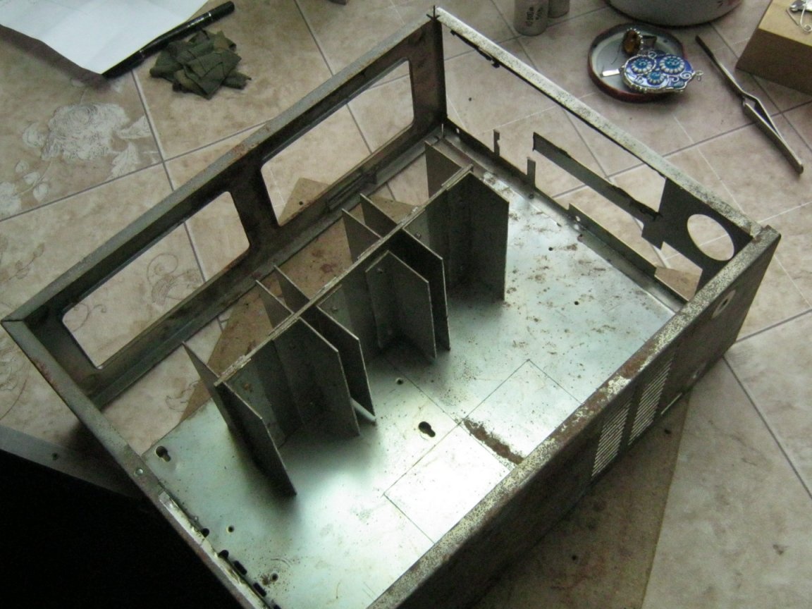
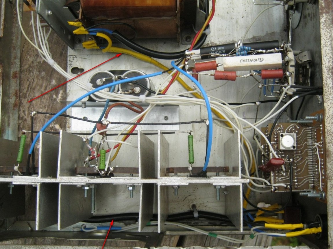
The main radiator for installing the regulatory elements was made independently of a thick aluminum sheet with riveted pieces of the same corner. Fastened with aluminum blind rivets, the joints were lubricated with heat-conducting paste KTP-8.
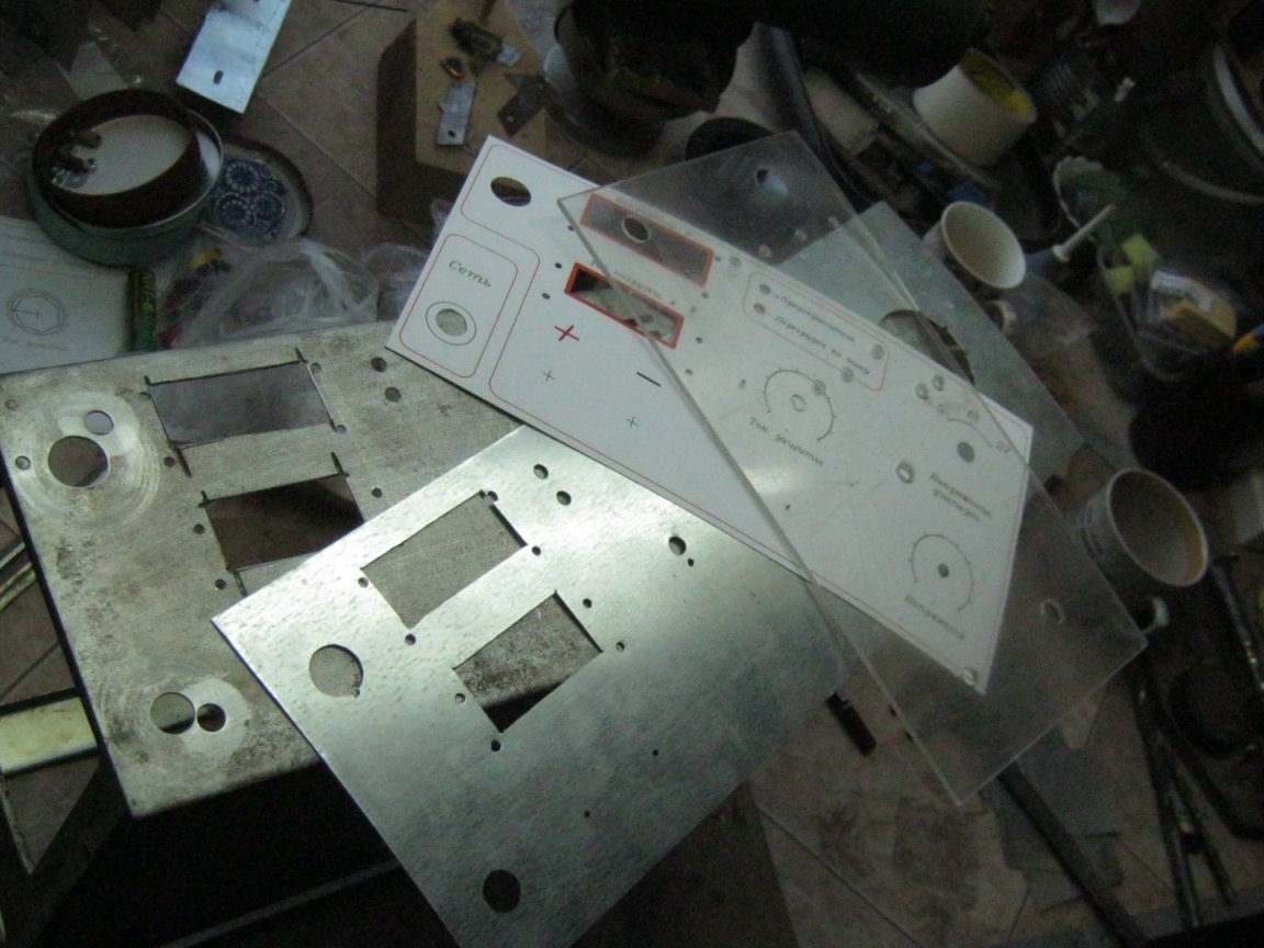
The regular panel of the case, the future in the front design, turned out to have ventilation openings and holes, we had to make a false panel. Explanatory labels, scales, etc. drawn in AutoCAD and printed with photographic quality on special thick paper. Holes and openings are carved with a scalpel. The front panel is covered with a transparent panel of organic glass. The panel is cut with a hacksaw for metal, the internal holes are sawn with a jigsaw on wood, and small ones are drilled. The panels do not have special fasteners, everything is held by regular fasteners of installation elements.
The internal holes and openings in the panel made of 0.5 mm roofing steel were sawn off with a jewelry jigsaw, in a standard drill or small abrasive disc with a small angle grinder. The holes are drilled and bored with a round file.
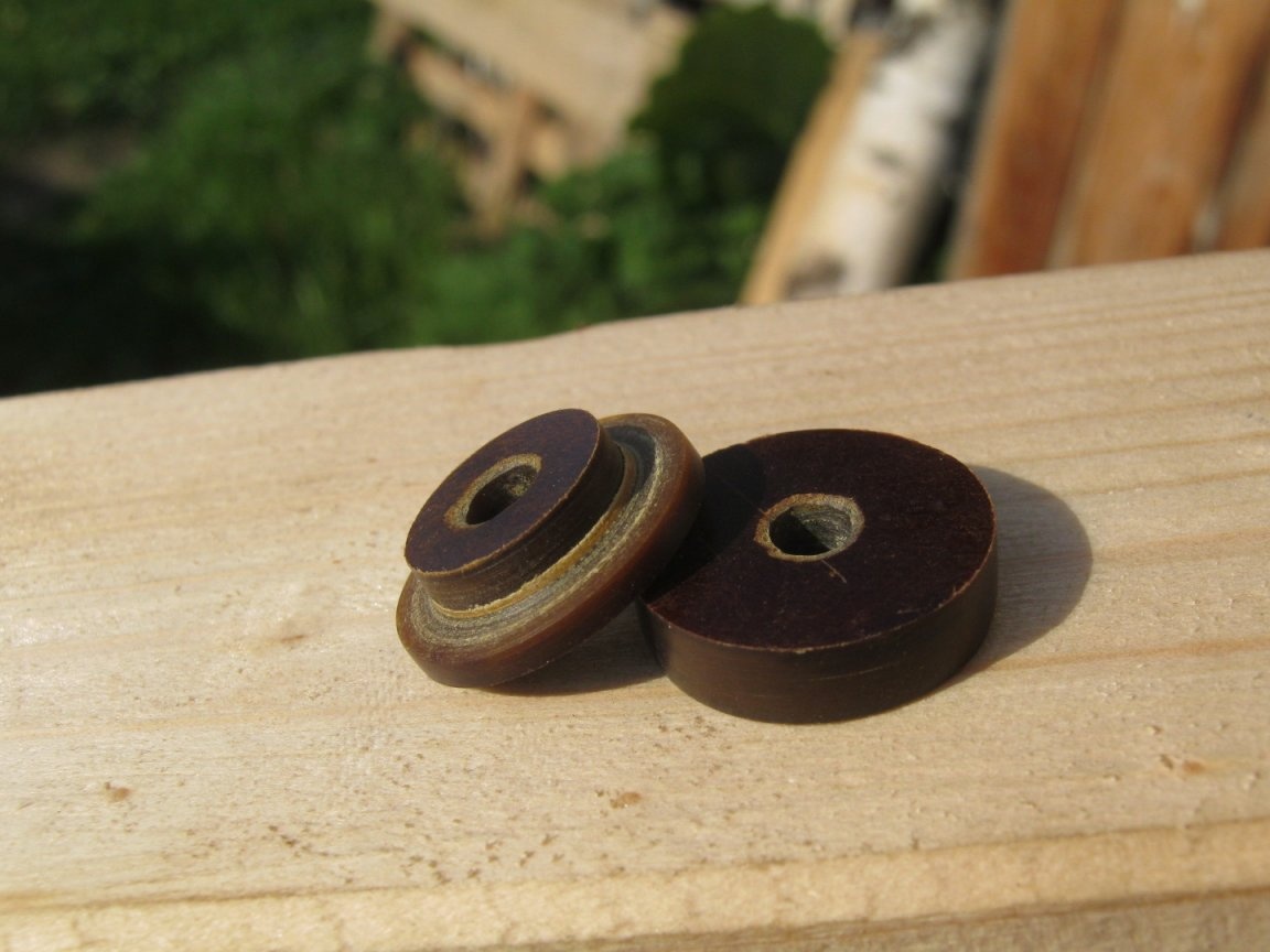
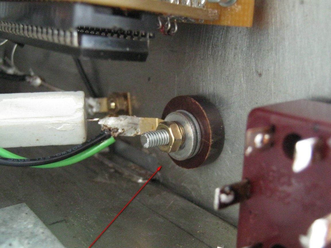
Output terminals - the negative terminal is screwed directly to the metal case, from the inside, a piece of thick tinned wire is soldered to it, to which all the "earth" ends are reduced. The positive terminal is elongated and insulated - a piece of the M4 screw is soldered to it and a textolite insulator is made.
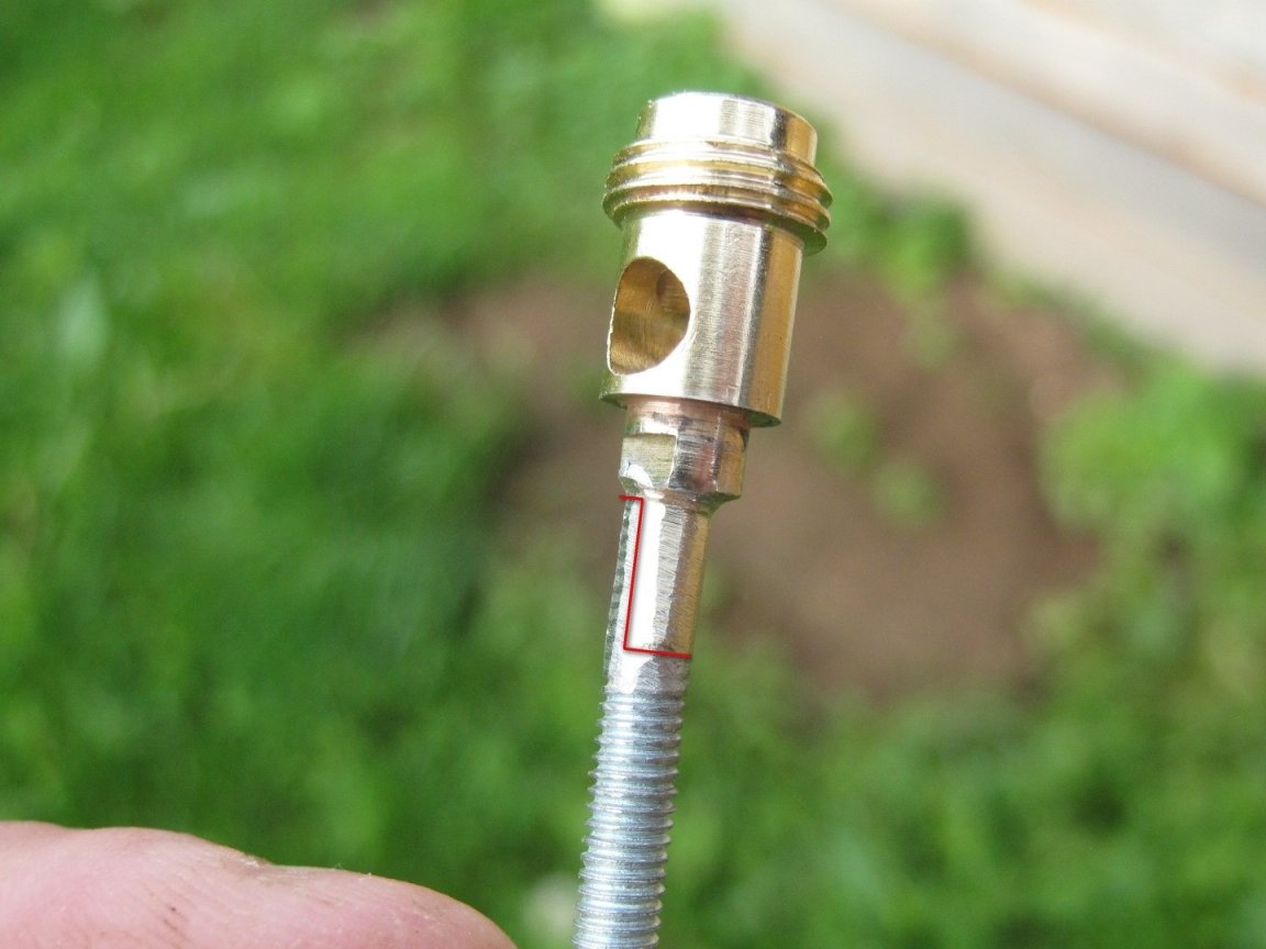
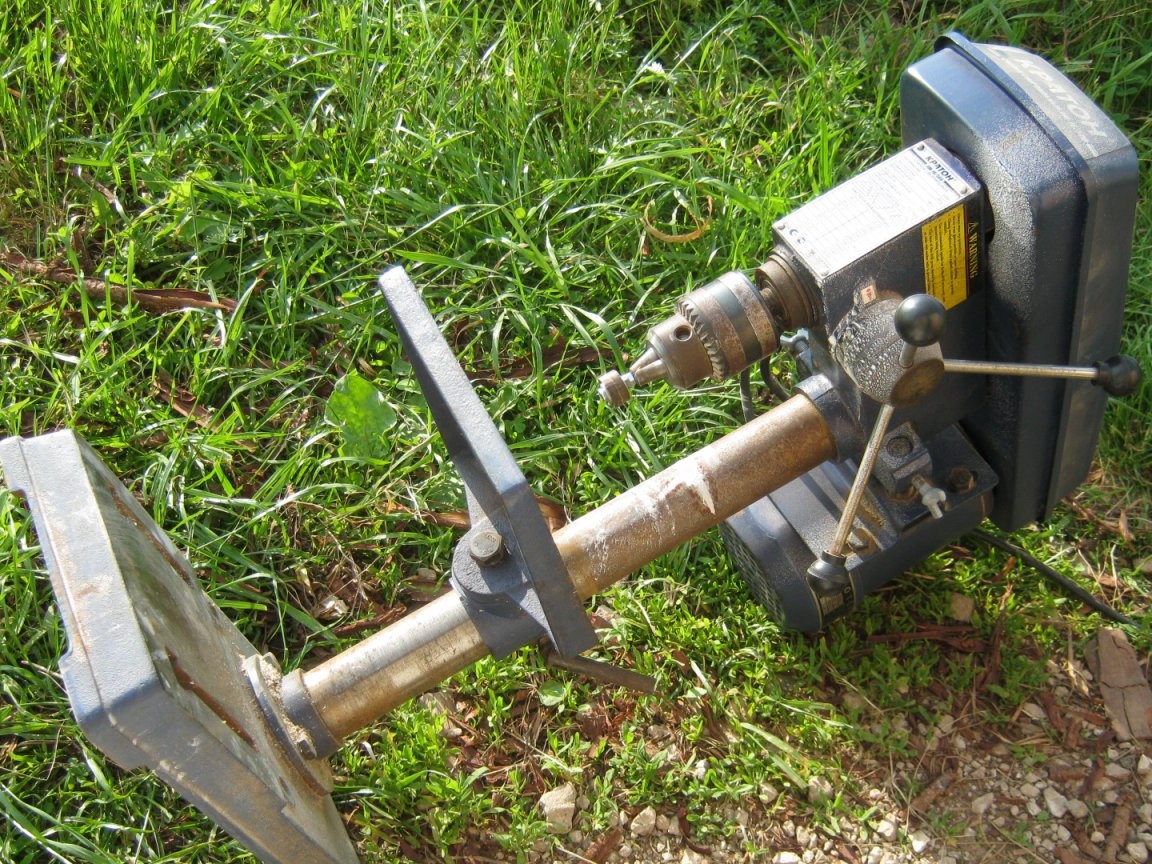
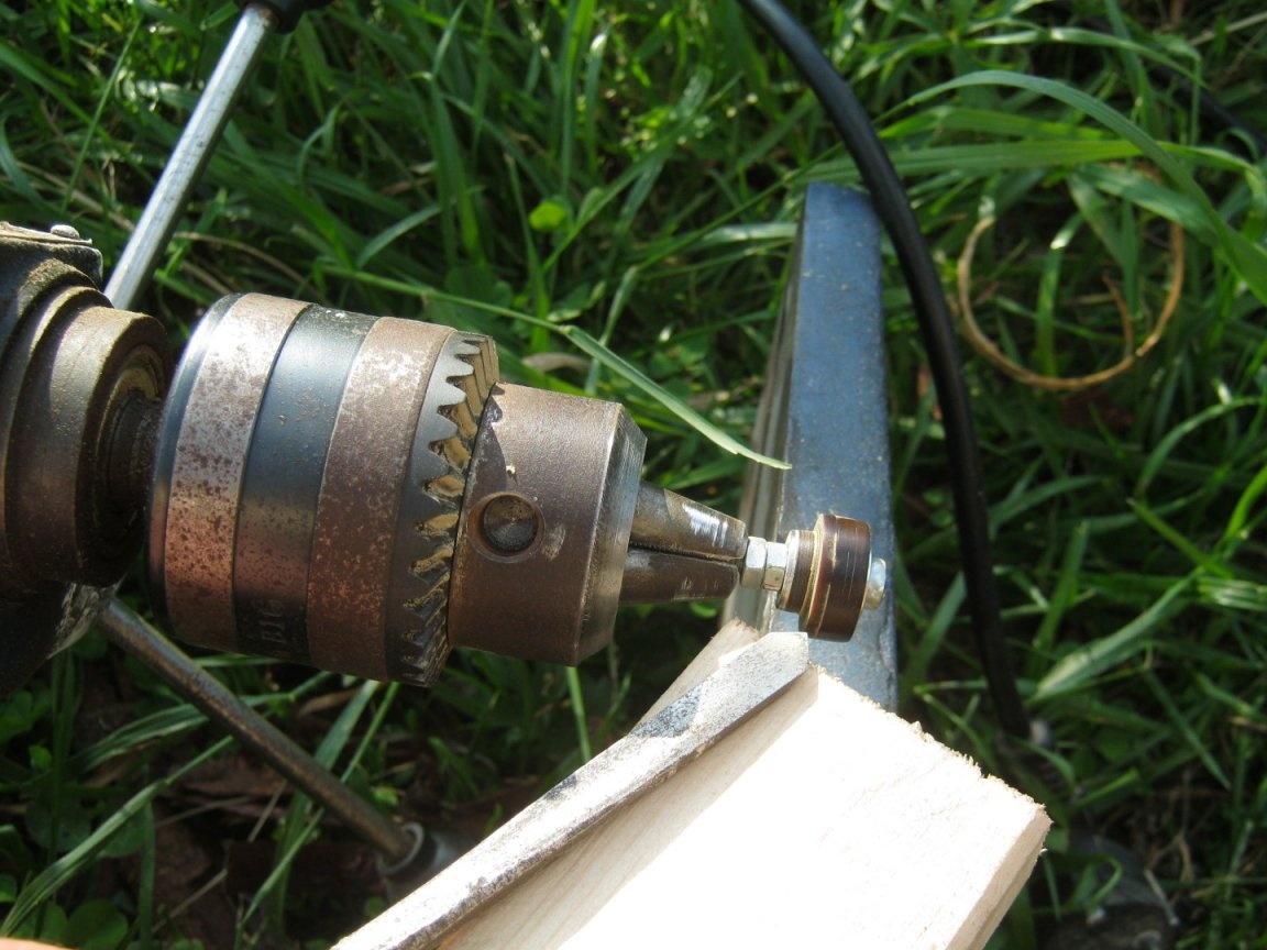
Parts of the insulator are sawn out of the plate with a jigsaw on wood and turned on a drilling machine.
After assembling the front panel, I installed the main controls for the device. I installed measuring instruments on improvised racks from long M3 screws.A wide masking tape was used as a light filter masking idle segments of indicators.
LEDs (not yet used - the front panel is used from a previous unfinished design) are tightly installed in the holes. They are held by a thick tinned wire, laid between the thermotube insulated terminals of the LEDs and soldered to a metal panel. The lens at the ends of the LEDs is framed with a file flush with a transparent panel.
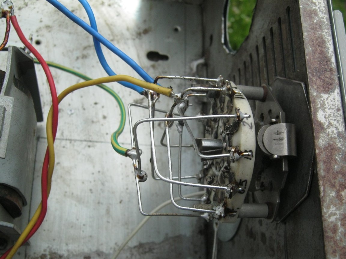
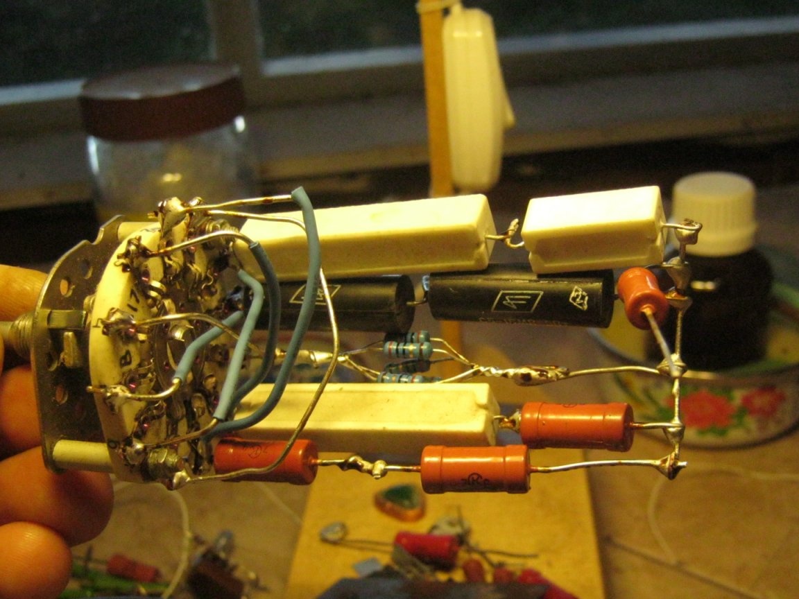
Parallel connection of the groups of contacts of the hard drive switches is made with a thick tinned wire. Before installation, the switches are configured by moving the limiter. On the petals of the switch SA3 mounted resistors R5 ... R8. My switch turned out to be with two groups of five contacts. Synchronously switched contacts were connected in parallel, similar to SA2, the fifth contact is used for another 10 mA range. In this case, range 4 is fixed (variable resistor R9 removed) at 100 mA. The values of the current-setting resistors and their power can be calculated by the formulas given in [1].
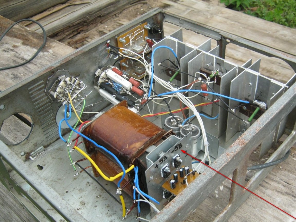
A transformer and a block of oxide capacitors C5 (2x10 000x50 V) are installed on a metal base. The power cord is temporarily connected to the petals of the transformer, the power leads of the secondary winding are soldered to SA2, and a rectifier is connected. By trial inclusion I was convinced of operability of this part of the circuit.
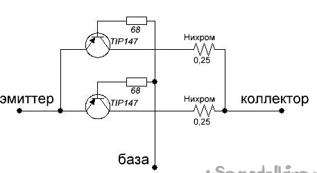
A microcircuit (optional), a diode bridge and an external control transistor (2xTIP147) are installed on a homemade cooling radiator. Replacing a powerful semiconductor device with a few less powerful ones is beneficial from the point of view of cooling - we evenly distribute heat sources over the radiator.
0.25 ohm current-aligning resistors are made of pieces (about 10 cm) of steel wire (made of a ribbed plastic hose for wiring). The wire is annealed in the flame of a gas burner, its ends are stripped and tinned with zinc chloride (soldering acid). Places of soldering are thoroughly washed with water, then the resistor wire is soldered with rosin.
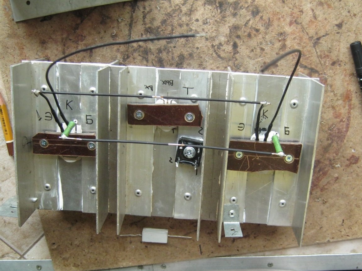
On the hard terminals of the mounting elements, several small elements with thin terminals are mounted. After checking the operability, the part of the circuit placed on the radiator is installed in the case and connected with short wires of a significant (if necessary) section. Health Check.
The inclusion of measuring instruments. As already mentioned, the specialized KR572PV2 microcircuit (ICL7107) requires a bipolar voltage of +5 V, -5 V. for its operation. Moreover, the measuring circuit of the ammeter is constructed in such a way [3] that its power supply unit must be completely isolated from other circuits. Awareness of this fact was worth several burnt printed tracks and a burned LSI. Well, good lessons are always expensive. The transformer had only two identical windings for +5 V and -5 V (the voltages common to both meters were assumed). It was possible to get out of the situation by applying a different circuit for switching on the rectifiers and assembling another similar power supply unit. In this case, two galvanically isolated PSUs were obtained.
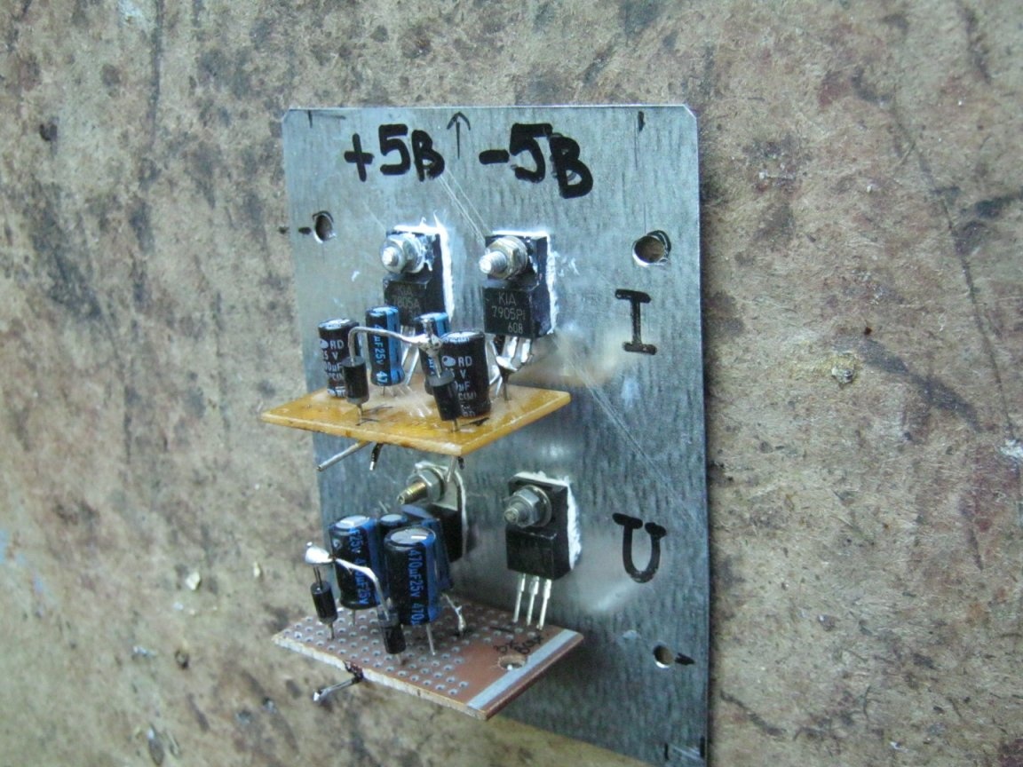
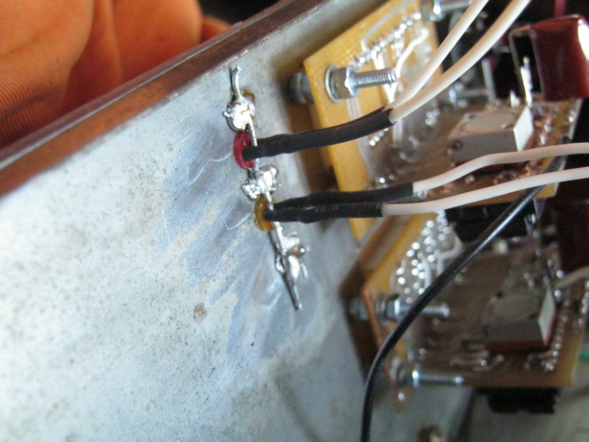
Two independent sources are assembled on separate boards and fixed to the standard flanges of microcircuits (TO-220 case). The current consumed by the measuring device is small, so the stabilizer microcircuits are used in a plastic design, which made it possible to mount them without insulating gaskets. The only 7805 with a metal flange (GND output of the microcircuit) in the PSU of the voltmeter is also installed without an insulating gasket, this is permissible by the circuit.
A metal board with power meters is installed on the end flange of the network transformer. Connections made, operability checked. By multi-turn tuning resistors on the meter boards [3], the displayed values of the devices are adjusted to the readings of an external multimeter.
Finally, a panel for a ~ 110 V socket was made, the socket itself was installed and its connection was made. The connection, as having a galvanic connection with the network, is additionally isolated from the metal case with a thick PVC pipe, a relatively soft cable is fixed in several places with nylon straps, and the solders are insulated with a heat pipe.
The temporary mains wire has been replaced by permanent wiring through the mains toggle switch and fuse holder. Harnesses and wires are laid in the same way - additional insulation from a metal chassis, mechanical fastening, isolation of soldering points.
The sides of the device chassis are covered with panels cut from galvanized steel roofing and mounted on blind rivets. The top cover is cut from the standard U-shaped cover of the system unit. Arrays of holes for cooling were drilled in the cover above the radiator and the block of resistor resistors R5 ... R8, the damaged paintwork was restored.
On the plexiglass panel around the handle for switching the current limit limits (SA3), the engraver made five scans and indicated the limits - 10 mA; 100 mA 0.3 A; 1 A; 3 A. Engraved indentations filled with dark paint.
Conclusions, work on bugs
The original scheme has undergone several changes and simplifications, they are all workable, and for some time operation has shown that they are quite convenient. For example, getting rid of resistors R3, R9. The introduction of another 10 mA limit made it very convenient to check the performance of the LEDs and measure the stabilization voltage of the zener diodes (reverse switching!).
During installation, a few points slipped from attention - capacitors bypass diodes of the rectifier bridge and fuse FU2 were not installed. Capacitors neutralize interference from switching low-frequency diodes, a fuse will help to save the transformer in the event of an accident. This will be the next revision. At the same time, it is worth using at least one of the LEDs - to indicate to them the blown fuse.
Literature
1. RADIOhobby Magazine No. 5, 1999
2. PGC, PGG switches, checklist.
3. Voltmeter, ammeter on K572PV2 (ICL7107).
Babay Mazay, June, 2019