
The master spends a lot electronic experiments with Arduino and discrete components, and also does a lot of other work, so he always does not have enough space on the workbench for current projects.
Since the master is not involved in large electronic projects, the experimental station should not be large. Enough to accommodate the layout, Arduino and several other parts. The master wanted the station to be powered by a battery so that he did not have to take up space with a power source every time he needed to test a simple circuit. A protective storage lid, a battery box and several loose parts were also desirable. The overall dimensions of this station are 20 cm wide, 15 cm deep and about 4.5 cm high, without a cover.
Step 1: Materials Needed
The only thing needed for this station is a pair of 3 mm square meters. plywood and some glue for wood.
You will also need:
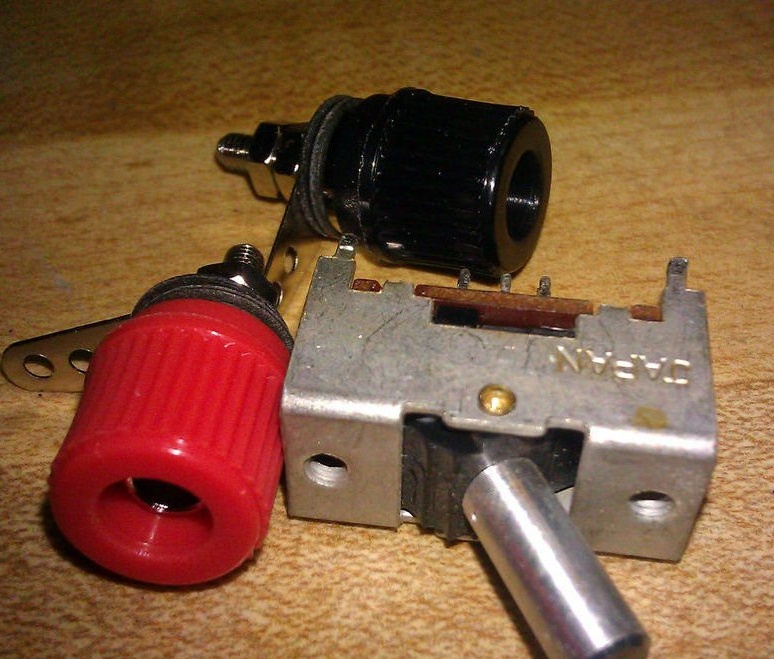
- Switch (almost any switch will work);
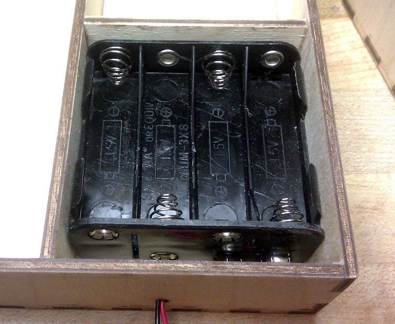
- Battery holder (in homemade holder 8 AA used);
- 9V battery clip;
- A small connector for connecting the battery wires to the wires of the power panel;
- Connecting plugs (red and black, Radio Shack);
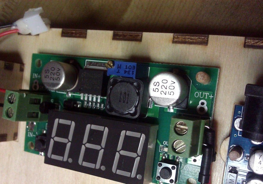
- Board voltage regulator with a voltmeter;
- Arduino Uno;
- Development board without solder, 300 tie points;
- A few centimeters 3 mm. wooden cuttings;
- 2 suitcase latches;
- Self-tapping screws 51 X 6 mm. - 16 pcs.;
- The wire;
- Solder and soldering iron;
- Drill with a diameter of 1.5 mm .;
- Drill with a diameter of 3 mm. for mounting holes;
- screwdriver;
The template presented in the next step is designed for laser cutting, but it will not be difficult to do with a saw. Just ignore the tabs and make simpler connections.
The master also etched the labels with a laser, but the labels can be made in many other ways.
A switch is also required. However, a mini toggle switch is a good alternative choice.
Step 2: Station Parts Template
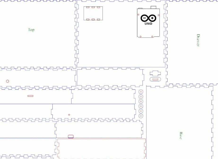
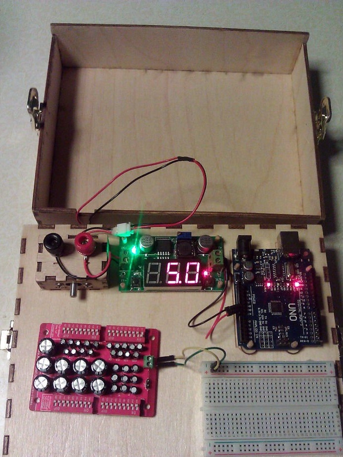
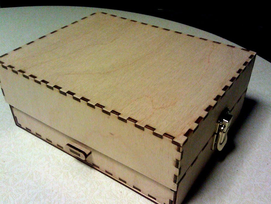
Here is a template for cutting plywood. There are four nodes: base, drawer, cover and power panel. The cover has one of the long sides hanging over the base. This is not an oversight. It was designed so that the protrusion, when the lid is closed, locks the box in place.
The base has a hole in the back for battery wires.There is a corresponding hole in the back of the box, and there is a recess in the lid for wiring to the power panel.
The file is in PDF format and can be edited using Inkscape. In addition, for Arduino Uno there is a template with holes for individual design. The .svg file is in compressed format.
As mentioned earlier, the master cut the parts with a laser, but this can also be done using conventional wood processing tools.
Files
Step 3: build the base
The master did not take any photographs during the assembly of parts from plywood, but it is quite simple.
All 4 nodes are a simple box. The main parts are those that have a straight edge on the long sides of large parts, a straight edge on the short side of small parts and a part with recesses along the entire length and one hole. This part is the back.
Glue 5 sides of the base together, making sure that the side with the stickers is on top and the hole on the back is on the lower left when viewed from the front.
The master also drilled several additional holes for mounting the regulator and installed the layout using double-sided tape.
Step 4: Assembling the Drawer
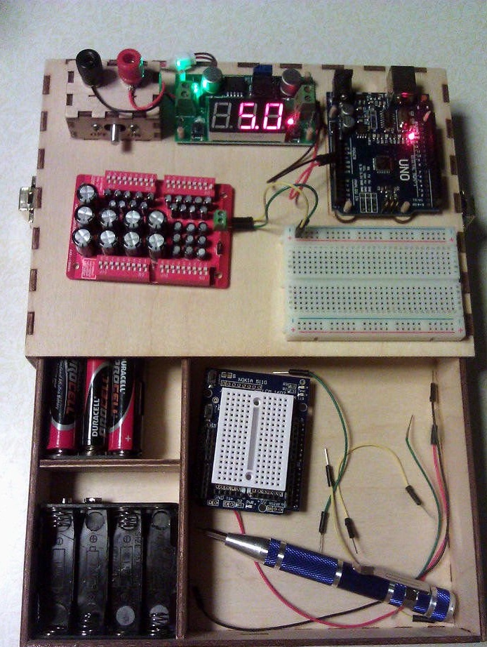
The box is also a 5-sided box, slightly smaller than the base and smaller than the lid. Assemble a box with a round hole in the back, bottom to bottom, when viewed from the front, just like the base. The two holes should match when the drawer is inserted into the base. A rectangular hole is located in front of the drawer. Assemble the drawer by gluing the cross-shaped part to the hole in the oval part. Then glue to the hole in the front of the drawer.
The master also installed a pair of partitions in his drawer, which are not in the layout. This helps keep the battery in check.
Step 5: Assembling the Cover
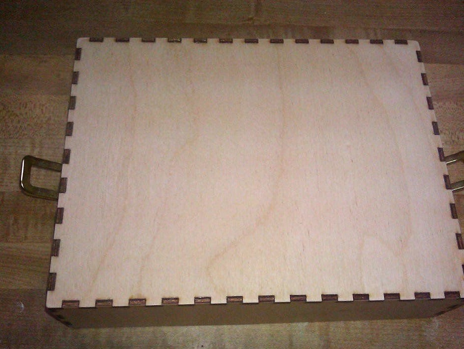
The lid is the last large of the 5-sided boxes. One of the long sides of the cover is approximately 9 mm. longer on the long side than the other. This will be the front of the lid that will hang over the drawer to keep it closed when the lid is in place. The back of the cover should be on the left when viewed from the front.
Step 6: reassembling the power panel
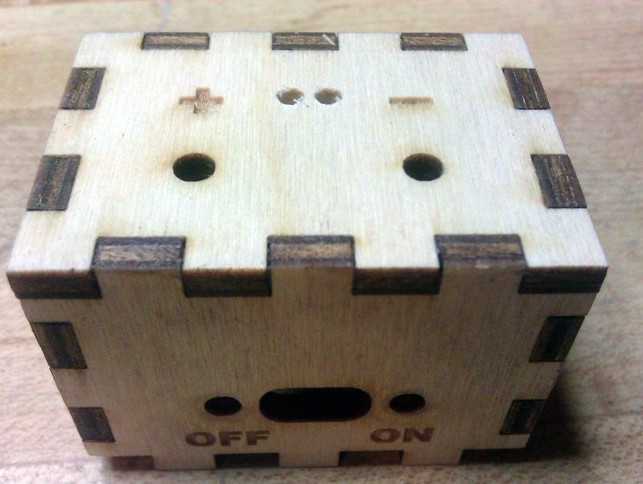
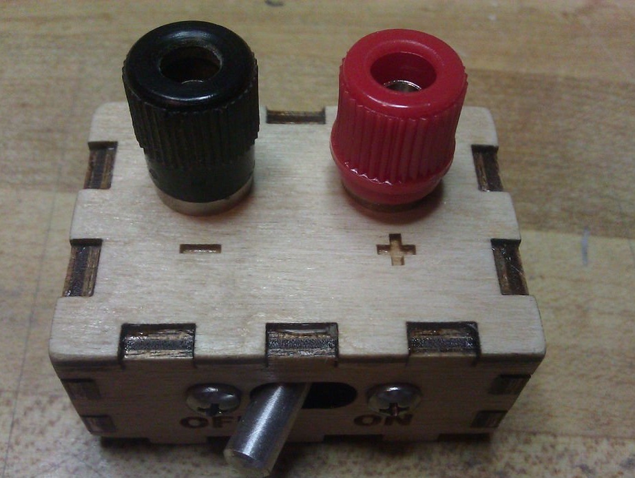
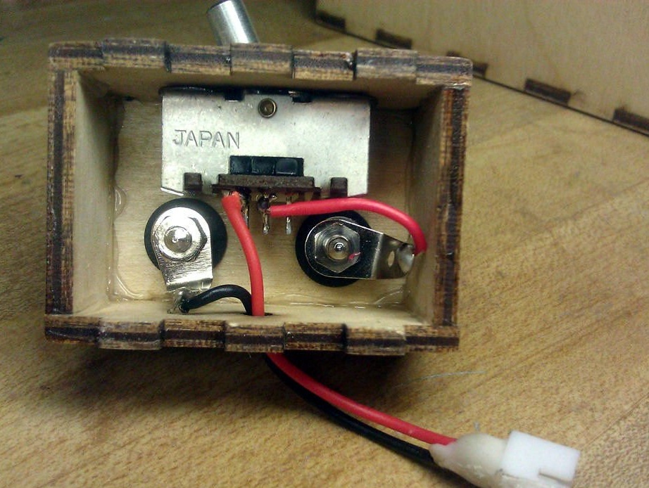
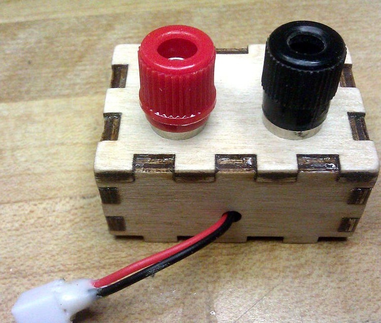
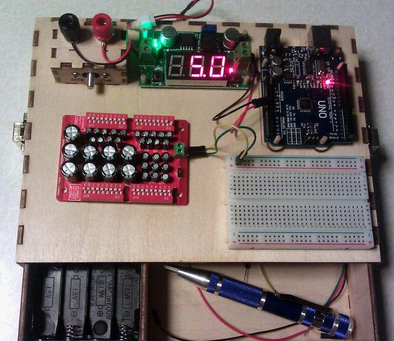
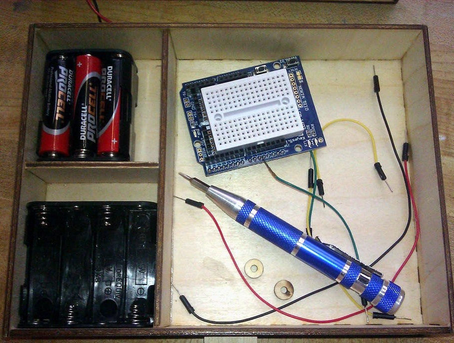
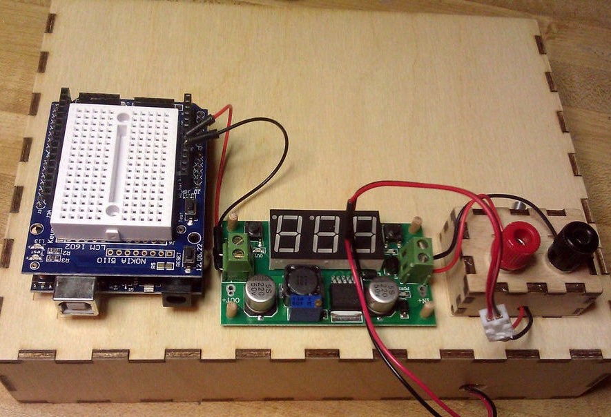
The power panel is another 5-sided box ... The long sides have six protrusions that align with the six rectangular holes in the base. The wizard installed the terminals, the switch and connected everything as shown in the figure.
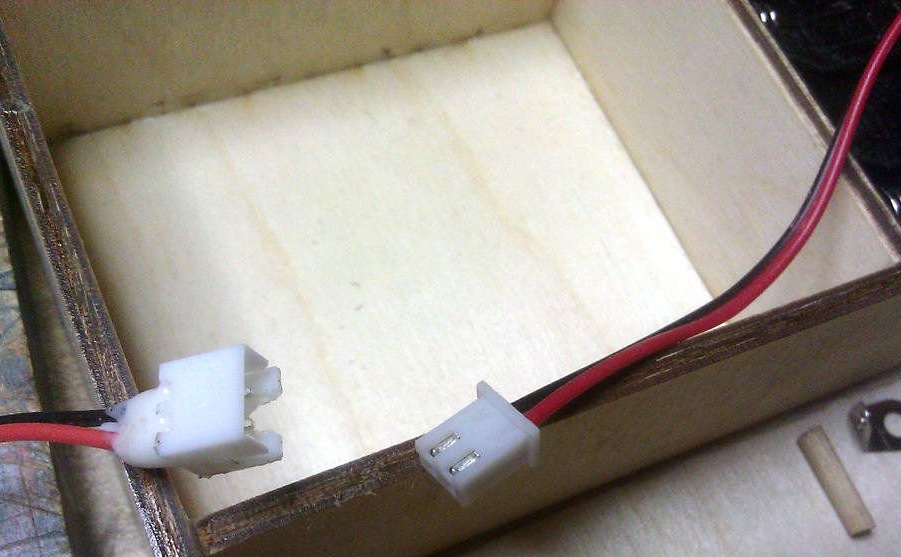
The findings of the 9-volt battery connector go through the hole in the back of the drawer and base, and then spliced to longer wires with a small battery connector at the end. Make sure that the wires are long enough to fully extend the drawer.
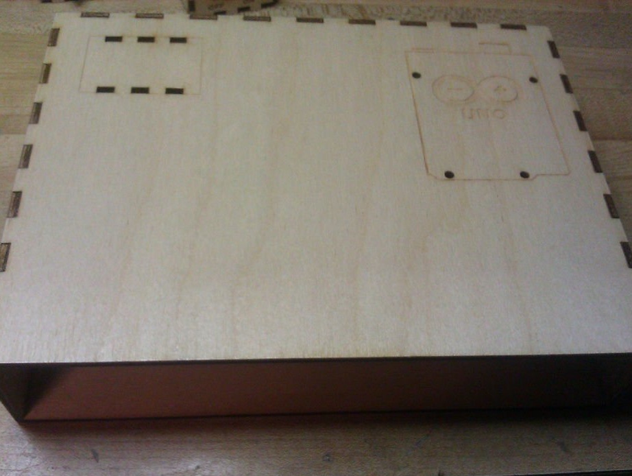
Step 7: Final work
You can leave this homemade product as it is, but the master polished it and covered it with one layer of polyurethane, polished it again with sandpaper with a grain size of 220 units to give the homemade product a more finished look.
Step 8: Installing the Latches
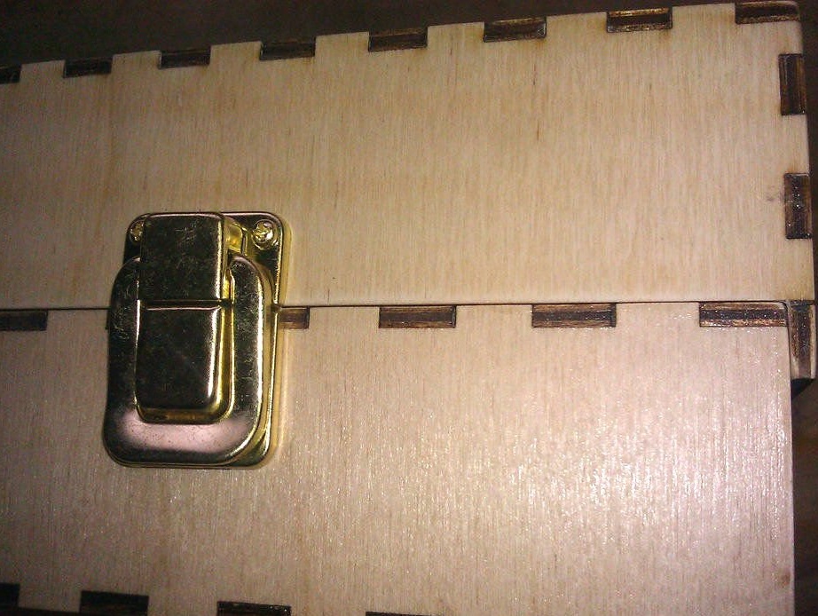
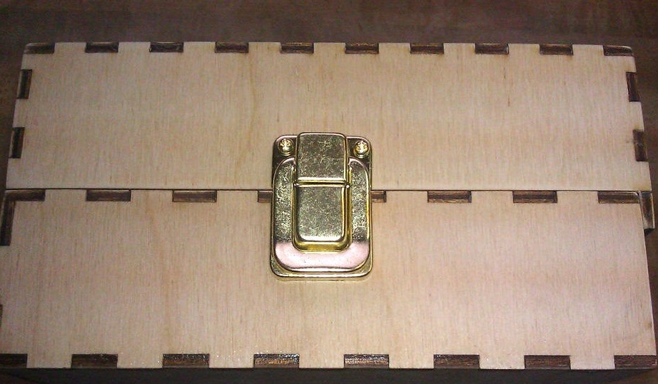
The master wanted the lid to be completely removable. It can be used as an optional tray for parts. Therefore, the master decided not to install the hinges, but to install the suitcase latches, one on each side.
Center the latches on each short side. Install a small part on the base first, then snap the latch and install the top. Drill 1.5 mm holes and secure the latches with 6 mm. small screws.
If the screws protrude inside the base, they will interfere with the drawer. Therefore, the master simply cut and polished the ends of the screws on the inside.
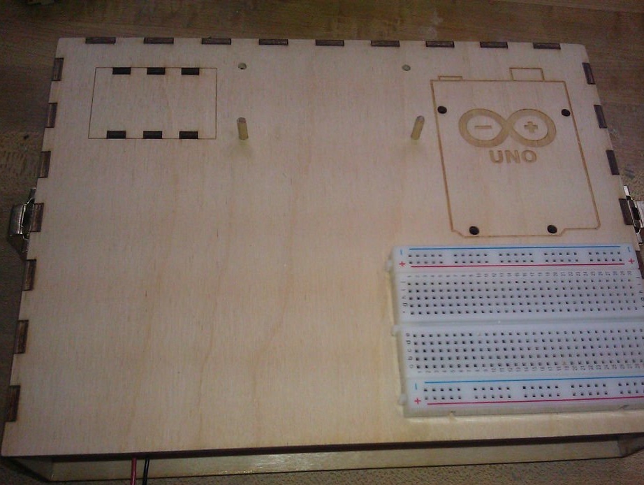
Step 9: Fine But Desirable Details
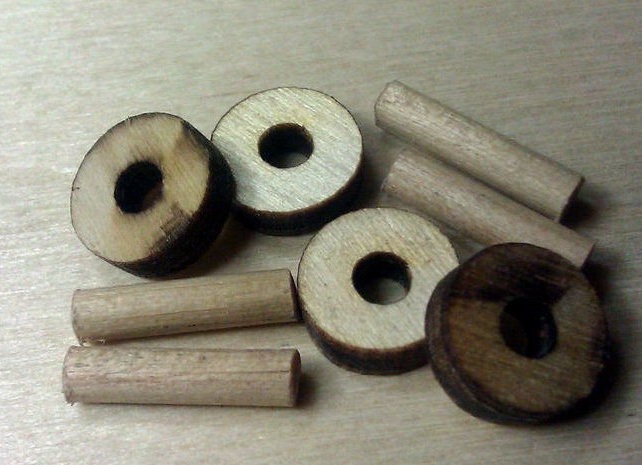
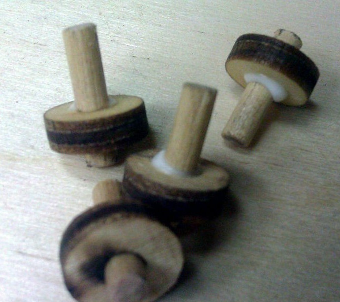
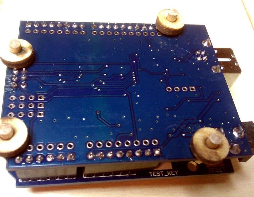
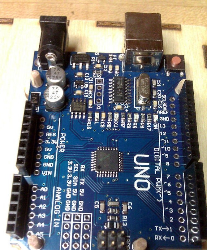
Small wooden “washers” are spacers that allow you to install the Arduino, but also remove them when they are not needed. The washers are glued to the dowels, allowing them to protrude from the bottom by about 3 mm, and the long ends are pressed into the mounting holes of the Arduino.Dowels must fit snugly. Arduino can then be inserted into the holes in the base.
Initially, the master wanted to install a power regulator using a double-sided tape, but decided to install it the same way as the Arduino. He installed the regulator and drilled one 3 mm hole, using its mounting holes as a guide. Before drilling the second hole, the master inserted the dowel into the first hole, then inserted another dowel into the second hole before drilling the other two.
The entire layout is also glued to tape.
Battery wires run through the back of the base through the hole and are connected to the pigtail from the power panel.