
Without a transformer concept, it works using a high voltage capacitor to reduce the AC voltage of the network to the required lower level required for the connected e circuit or load.
The specification of this capacitor is selected with a margin. An example of a capacitor that is commonly used in circuits without transformer power is shown below:
This capacitor is connected in series with one of the AC input voltage signals.
When mains alternating current enters this capacitor, depending on the size of the capacitor, the reactance of the capacitor comes into effect and limits the alternating current of the network from exceeding the specified level by the indicated value of the capacitor.
However, although the current is limited, the voltage is not limited, therefore, when measuring the rectified output without a transformer power source, we find that the voltage is equal to the peak value of the AC network, it is about 310 V.
But since the current is sufficiently lowered by the capacitor, this high peak voltage is stabilized by a zener diode at the output of the bridge rectifier.
Zener diode power must be selected in accordance with the permissible current level of the capacitor.
Advantages of using without a transformer power circuit
Cheapness and at the same time the efficiency of the circuit for low-power devices.
Without the transformer power circuit described here, it very effectively replaces a conventional transformer for devices with a current power below 100 mA.
Here, a high voltage metallized capacitor is used on the input signal to lower the mains current
The circuit shown above can be used as a DC 12V power supply for most electronic circuits.
However, after discussing the advantages of the above construction, it is worthwhile to dwell on several serious drawbacks that this concept may include.
Disadvantages without a transformer power circuit
Firstly, the circuit is unable to produce high current outputs, which is not critical for most designs.
Another drawback, which certainly requires some consideration, is that the concept does not isolate the circuit from the dangerous potentials of the AC network.
This drawback can have serious consequences for structures associated with metal cabinets, but it will not matter for blocks that are all covered in a non-conductive housing.
And last but not least, the aforementioned circuit allows power surges to penetrate through it, which can lead to serious damage to the power circuit and the power circuit itself.
However, in the proposed simple power supply without a transformer circuit, this drawback was reasonably eliminated by introducing various types of stabilizing steps after the bridge rectifier.
This capacitor makes instantaneous high voltage ripple, thus effectively protecting the associated electronics with it.
How the circuit works
1. When the AC mains input is turned on, capacitor C1 blocks the mains input and limits it to a lower level determined by the reactance value C1. Here we can roughly assume that it is about 50 mA.
2. However, the voltage is not limited, and therefore 220V can be on the input signal, allowing you to reach the next stage of the rectifier.
3. The bridge rectifier rectifies 220V to a higher DC 310V, to peak AC waveform conversion.
4. The DC 310V is quickly reduced to a low-level DC zener diode, which shunts it to a value according to the zener diode rating. If a 12V zener diode is used, then the output will be 12 volts.
5. C2 finally filters the DC 12V with ripples, into a relatively clean DC 12V.
Circuit example
The driver circuit shown below controls a tape of less than 100 LEDs (with an input signal of 220V), each LED is designed for 20mA, 3.3V 5mm:
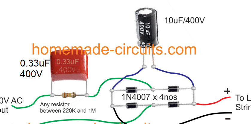
Here, the input capacitor 0.33 uF / 400V produces about 17 mA, which is approximately correct for the selected LED strip.
If the driver is used for a larger number of similar LED strips 60/70 in parallel, then simply the value of the capacitor is proportionally increased to maintain optimal illumination of the LEDs.
Therefore, for 2 tapes included in parallel, the required value will be 0.68 uF / 400V, for 3 tapes replace with 1uF / 400V. Similarly, for 4 tapes it should be updated to 1.33 uF / 400V, and so on.
Important: although the limiting resistor is not shown in the circuit, it would be nice to include a 33 Ohm 2 W resistor in series with each LED strip, for added security. Can be inserted anywhere sequentially with individual ribbons.
WARNING: ALL CIRCUITS MENTIONED IN THIS ARTICLE ARE NOT ISOLATED FROM THE AC NETWORK, SO ALL SECTION OF THE CIRCUIT IS EXTREMELY DANGEROUS TO TOUCH WHEN CONNECTING TO THE AC NETWORK.