Diagram of a multi-position charger using capacitor discharge.
Greetings to lovers homemade bestdiy.washerhouse.com away. I want to introduce a charging scheme for several batteries at the same time. Which battery does not matter, adjust to your needs ...
Schematic diagram of the circuit, for the automatic charge of several batteries simultaneously uses a capacitor discharge.
3 stages of a multi-position charger circuit using capacitor discharge:
1. operational amplifier amplifier comparator detector cascade
2. On / off interval generator based on IC 555
3. cascade capacitor discharge circuit
The purpose of the operational amplifier is to maintain a continuous battery charge, and accordingly turn off / restore. The charging process is carried out through a capacitor discharge system.
We consider the steps in detail:
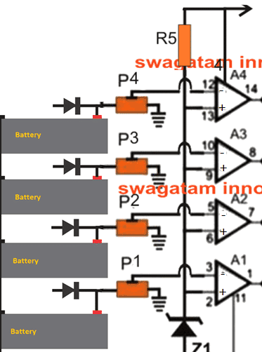
Operational diagram of Operational Amplifier for battery charging.
The first stage can be seen below:

parts list:
operational amplifier: LM324
potentiometers: 10K
Zener diode 6V / 0.5 Watt
R5 = 10K
diodes = 6A4 or analogs.
The considered scheme for connecting 4 batteries at the same time, and therefore we use 4 op-amps. The A1-A4 operational amplifiers are powered by four IC LM324 nuclear operational amplifiers, each of which is configured as separate compartments to detect an attached battery according to charge levels.
As can be seen in the diagram, the non-inverting inputs of each of the operational amplifiers are configured with the corresponding positive battery signals to provide the required battery voltages.
The advantages of each of the batteries are associated with the output of the capacitor discharge, which will be discussed in the next part of the article.
Inverting the pins (-) of the op-amp are connected through a single common zener diode.
Potentiometers are connected to the battery (+) and are designed to configure the shutdown of a charged battery, according to the voltage of the zener diode. Presets are set so that when the corresponding battery voltage reaches the full charge level, the proportional value at the output (+) of the operational amplifier exceeds the reference level (-) of the contact zener diode.
The above situation immediately turns the op-amp output from its initial 0 voltage to a high logic equal to the supply voltage level.
This maximum at the output of the operational amplifier triggers the IC 555 chip so that the IC 555 performs on-off switching at intervals for each attached capacitor reset circuit ...
IC 555 chip for periodic on / off generation.
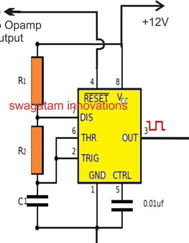
The following diagram shows a cascade based on IC 555, for periodically generating on / off and then resetting the capacitor.

parts list
IC = IC 555
R2 = 22K
R1, C2 = calculated to obtain the desired charge discharge cycle rate
As shown in the above diagram, terminal # 4, which is the reset terminal of the IC 555, is connected to the output of the corresponding stage of the operational amplifier.
Each of the operational amplifiers will have its own separate IC 555 stages along with the capacitor reset stage.
When the battery is in the process of charging and the output of the operational amplifier is kept at zero, the IC 555 remains off, however, at the moment when the corresponding connected battery is fully charged and the corresponding output of the operational amplifier becomes positive, the IC 555 connected to this battery is activated, which leads to to the fact that its output terminal # 3 generates periodic on / off cycles.
Pin # 3 of IC 555 is installed with its own individual capacitor reset circuit, which is responsible for turning on / off cycles from step IC 555 and starts the process of dropping the capacitor to the connected battery.
To understand how the reset capacitor behaves in response to the on / off cycles of the IC 555, see the following section of the article:
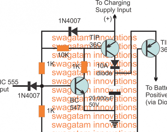
Capacitor Reset Operation Scheme:
In accordance with the request, the battery must be charged through the capacitor discharge circuit, as follows:
• As long as the IC 555 stays off, the BC547 receives an offset through its 1K base resistor, which in turn holds the TIP36 transistor in the ON position.
• This situation allows the collector capacitor to reach its maximum value. In this position, the capacitor is charged and awaits discharge.
• The moment the IC 555 activates and starts the shutdown cycle, the shutdown periods turn off the BC547 / TIP36 pair and turn on the TIP36, which instantly closes and dumps the charge from the capacitor to the appropriate battery.
• The next turn-on cycle from IC 555 returns the situation to the previous conditions and charges the 20,000 uF capacitor, and again, with the next follow-up turn-off cycle, the capacitor is allowed to discharge its charge through the corresponding TIP36 transistor.
• This happens continuously until the corresponding battery is charged.
All operational amplifiers for each connected battery work in the same way, adjusting the status of the connected battery.
Good luck

