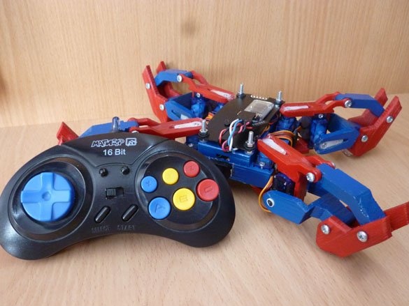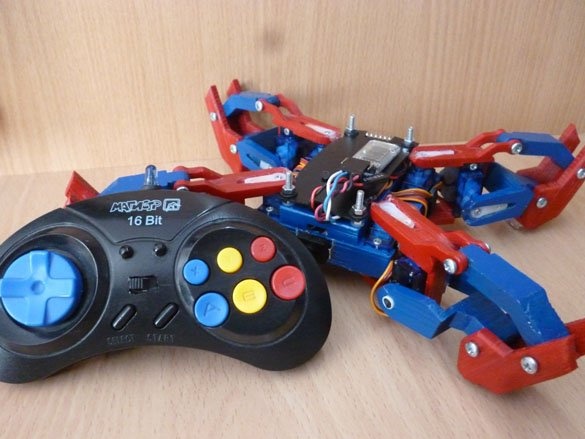
Greetings to all readers. Today I will share instructions for upgrading or “upgrading” a previously manufactured quadrapod model (four-legged walker robot). A little bit about why this “upgrade” is needed. In the previous version, the controller was ESP8266-12F, and its outputs were barely enough for 8 servos. I wanted to add something, but there were no free conclusions. In addition, I do not like (I find it uncomfortable) to control a robot model via touch phone. There is no sensation of pressing a control button. And the third reason, the ESP, which stood on the quadruple, burned out GPIO10 (possibly due to the fact that this pin is used for communication with memory), and without a single servo drive, the motor ability is lost. So, the essence of the “upgrade” is replacing the control board with Arduino Pro Mini. Management will be via Bluetooth channel.
Video:
It is necessary:
- Arduino Pro Mini Atmega 328 5V
- Bluetooth module HC-05 or similar.
- Old laptop battery (optional if there is a Li-ion 18650)
- Servo SG-90 8 pcs.
- Button with fixation
- connecting wires
- Dupont 2.54 mm 1x4 and 1x2
- 6 mm charging socket
- USB-TTL
- Bolts 3x12
- 3 mm thread tap
- Plastic washers 4mm and 6mm
- 3mm nuts
- Drills for metal 3 mm, 4mm, 6mm
- Lollipop 3 pcs
- drill
- Set of tools
- Stationery knife
Step 1 Making the case.
If you have already made this quad, you will need to completely disassemble it. All wires from the ESP must be soldered.
In my previous article about this quadropod, I described in detail the process of manufacturing and assembling the case, there is no point in repeating it. We take the archive with details, instructions and photos from step 1 of the next articles.
We print the details, paint if you want, but do not collect everything together.
Step 2 Upgrade your legs.
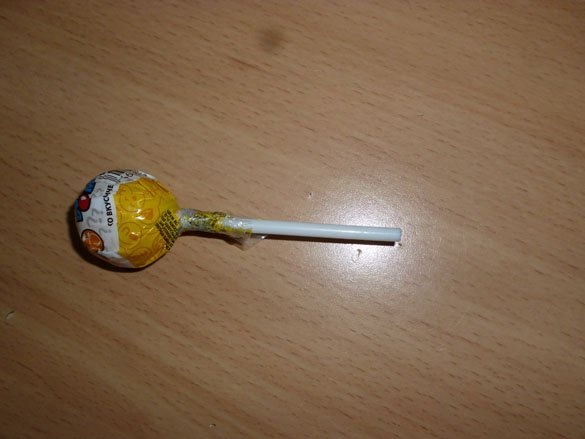
The previous model had large backlashes at the junction of moving parts. It turned out so because of small inaccuracies in the calculation of parts, as well as small shifts when printing these parts. As a result, the legs of the robot dangled quite strongly, and when walking it seemed that something was carrying a couple of tons, and not a small quad. Chupa Chups will help us in solving this problem! Or rather the tubes from him. Chupa-chups should be bought in a standard size, that is, small:
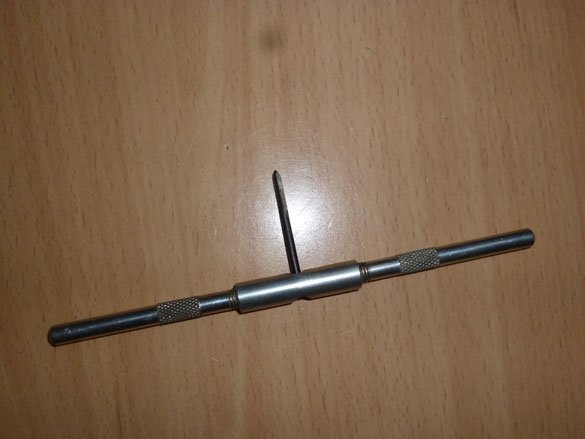
To begin with, inside the Chupa Chups tube, you need to cut the thread. Bremen 3mm thread tap:
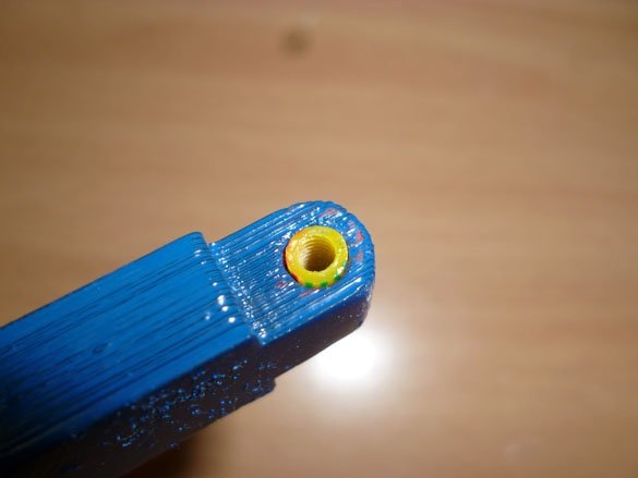
And cut the thread. It is more convenient to do this until Chupa Chups is eaten. It’s convenient to hold onto the lollipop itself while you thread the pipe from the other end.When cutting, you should not make a lot of effort, since plastic tubes are easily twisted. Therefore, we act like this: screw a 3-4 mm tap on a millimeter, then unscrew it, clean the tap, screw it again by 6-7 and so on. Having cut the thread by about 10 mm, we stop and take the quadrupod details. In the places where the parts are connected, the outer holes of the parts (the red parts of my legs), into which the bolts were screwed before, are drilled using a 3 mm drill. This is necessary so that the bolts pass freely, but do not hang out. The holes that are inside the joints in my photo are the blue parts of the legs, we drill a 4 mm drill. Inside these holes we will insert bushings from the Chupa Chups tubes. We insert a tube with threaded thread into the prepared hole and cut off the sleeve of the length we need:
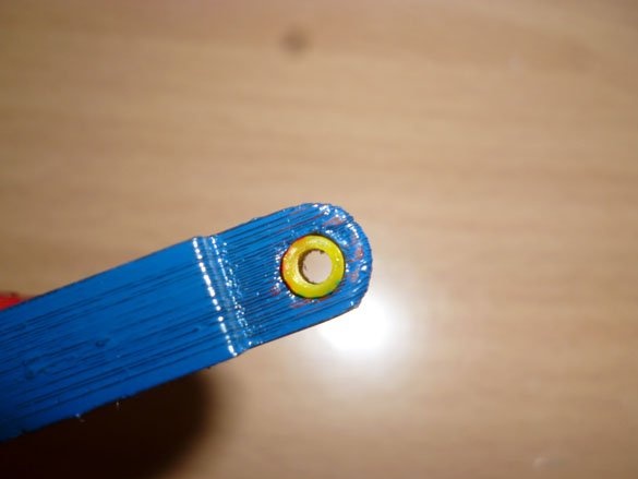
I have them in yellow, but you can have white, the difference is not what, they are still not visible:
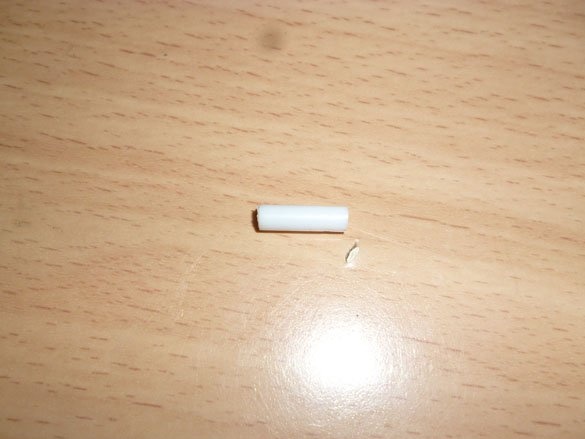
In the remaining tube, cut the thread again to a depth of about 10 mm. Then we do this with all the internal holes on the legs, there are 3 on one leg, only 12 bushings are needed:
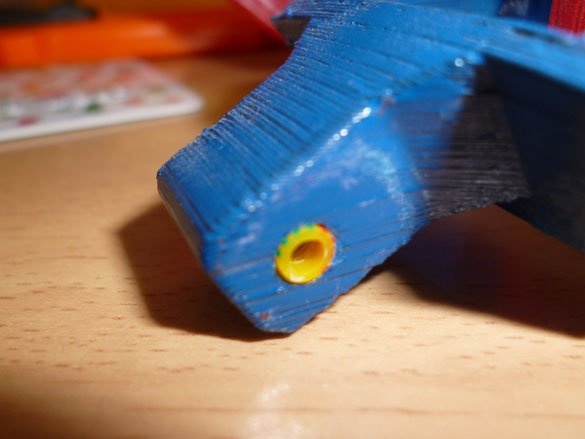
During assembly, 3x12 bolts will be screwed into these bushings.
On the end of the legs it is worth sticking silicone, furniture lining:
Step 3 Preparing the batteries.
The batteries that were standing with me worked out. If your batteries are intact, you can skip this step.
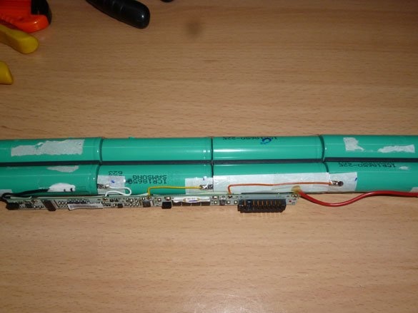
I really did not want to wait for the delivery of Li-ion 18650. And so we will go the other way. I had an old Li-ion battery from a laptop lying around. I think many masters find this in bins. Inside them there are all the same elements of the 18650. And even if they weren’t enough for the laptop, it would do for such a small toy. We disassemble the laptop battery and see the 18650 elements soldered together and the control board:
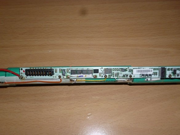
First removes the board so that it does not interfere:
Taking the pliers, we divide the battery into pairs soldered in parallel:
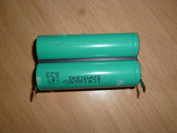
That's exactly them we will put inside the case.
Step 4 Modernization of the housing.
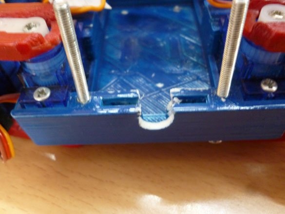
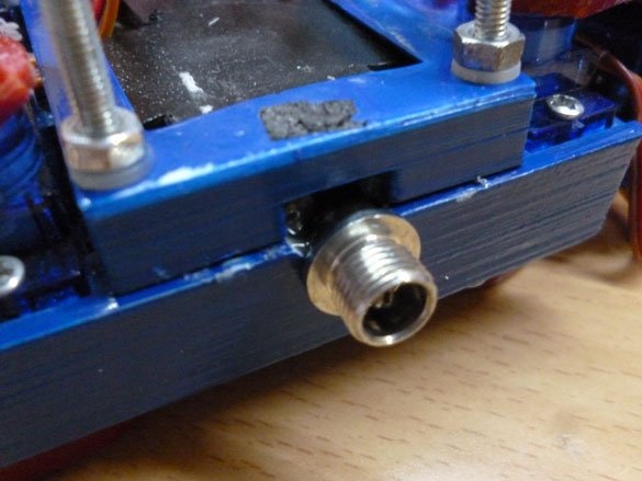
There were also inconveniences with the case. Last time I charged the wire with the connector to charge the batteries. This is not very convenient, the wire hung all the time and clung to everything in a row. Therefore, we make a slot for a normal charging socket:
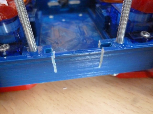
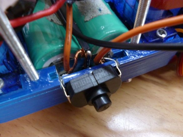
On the other side of the case we make a slot for the power button. There are a lot of buttons, so be guided by what you have, the main thing is that the button be fixed in position:
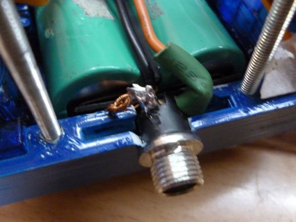
We use the socket for charging 6 mm. It fits here perfectly. We insert the batteries, insert the socket. Solder the plus from the batteries to the central pin of the socket, and simply wire one more wire up, minus the solder to the external contact of the socket, and also, as with the plus, put the negative wire up:
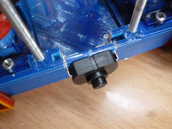
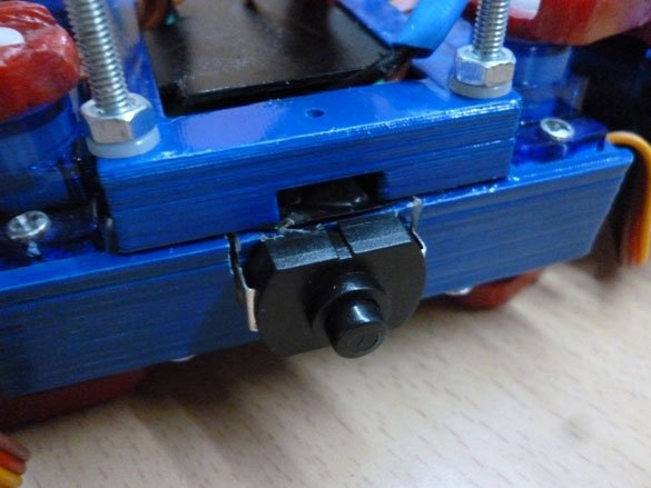
We install the button in a specially prepared place for it:
Solder the button into the gap of the positive wire, which we pulled up:
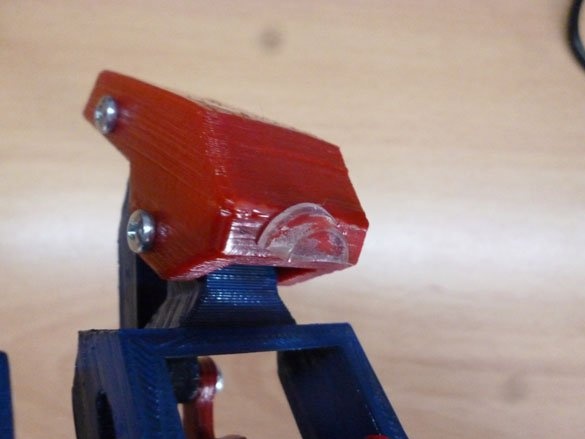
We close the case from the top with a lid, removing two wires upward:
Step 5 Upgrade the control electrics.
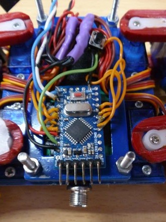
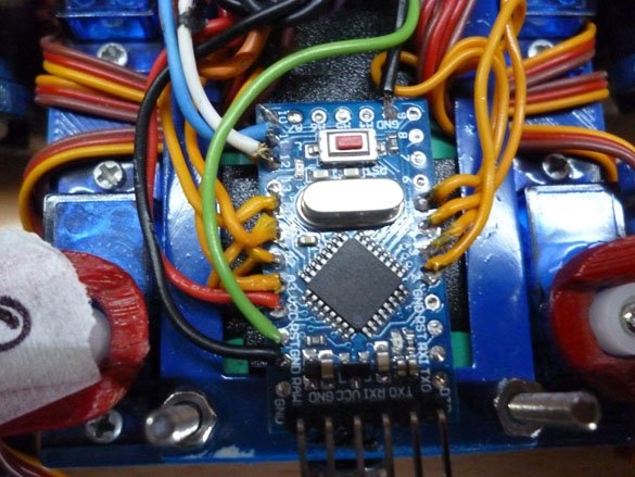
We change the control board to the Arduino Pro Mini. We need a version with Atmega 328 and running on 5 volts. I will give a little advice. Arduino is better to flash before installing on the quad. So that there are no random actions from the servos when turned on. The board needs to unsolder the connectors - pins only on the side of the terminals TX, RX, VCC, GND. We will connect, that is, solder, the wires from the servos directly to the board, without connectors. We glue the board on a double-sided tape near the charging socket and begin to solder. The servos are numbered according to the clock hand, first the drive on the case, then the drive to lift this leg, then the drive on the case, the next clock hand and so on.
The layout of the servos is as follows:
Servo 0 - A3 (17) (viewed from above, the charging socket is towards you, the left leg is closer to the socket, the drive is on the case)
Servo 1 - A2 (16) (left leg closer to the socket, lift drive)
Servo 2 - A1 (15) (left leg closer to the button, drive on the case)
Servo 3 - A1 (14) (left leg closer to the button, lift drive)
Servo 4 - PIN 5 (right leg closer to the button, drive on the case)
Servo 5 - PIN 4 (right leg closer to the button, lift drive)
Servo 6 - PIN 3 (right leg closer to the socket, drive on the case)
Servo 7 - PIN 2 (right leg closer to the socket, lift drive)
Solder the signal wires from the drives according to the diagram above. Solder power wires together and solder two more wires. One to power the Arduino. Plus from the batteries, solder in contact 5V arduino. The second is to power the Bluetooth module. It is also necessary to display the Reset button from Arduino to fill in the sketch. And solder the wires to Pin 11 and Pin12, you need to connect to the Bluetooth module. After all the manipulations, it turns out something like this:
And a little closer:
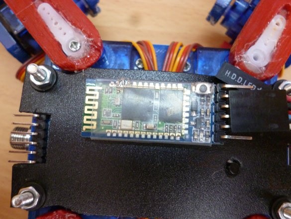
To connect the Bluetooth module, you need to output the Dunopt 1x4 connector. It should have a plus from the battery, GND, wire TX, RX. On the arduino, Pin 11 –RX, Pin 12 –TX. You need to connect TX on Bluetooth to the RX pin on the arduino, RX on Bluetooth to the TX pin on the arduino. We collect four wires in one connector and output to the top. Bluetooth modules are different, the pinout is different for everyone, so look carefully at the signatures of the conclusions. Bluetooth module with double-sided adhesive tape:
Step 6 Fill the sketch.
To fill the sketch, you need to download the Arduino IDE from official site.
We need two libraries Servo and SoftwareSerial. Download and install them in the environment:
ibre_softwareserial.rar
libre_servo.rar
After that, download and fill in the sketch:
ard_quadrapinky_bt_ser.rar
Step 7 Connection to the control panel.
As a control panel, we will use the Bluetooth remote control made by me:
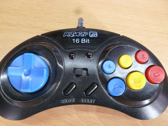
It can be made by instructions.
Add bluetooth module as follows instructions. It also describes in detail the configuration process and connecting the modules to connect with each other.