» Topics » Advice »Amplifier for laptop with radio tubes

Amplifier for laptop on radio tubes


The single-cycle amplifier is made using a 6F5P lamp, it is very convenient, since this lamp contains actually two lamps, one for the preliminary stage and the other for the terminal one. The lamp has good characteristics and you can assemble an amplifier with a power of about 5 watts on it. (translated into Chinese watts, this is somewhere around 12-20 watts). As a power source, the so-called "electronic transformer ”, which is used to power 12 volt halogen lamps for interior lighting. Suitable transformers are used as output transformers; purchased on istok2.com there you can choose from several options, more expensive and better, and cheaper with average characteristics. Radio tubes and lamp panels were also purchased there. The remaining parts are purchased in radio parts stores, they are widespread. The case was decided to use from the case of an external HDD.

The following scheme was chosen for the project, only the printed circuit board was developed differently, immediately on 2 channels:
Amplifier for laptop on radio tubes

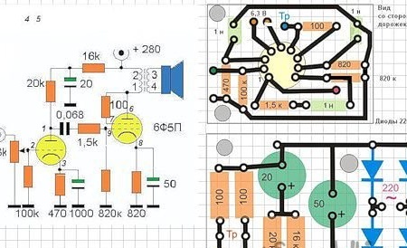
The printed circuit board was developed using the program Sprint-Layout-6-0 freely distributed.

The circuit itself is a classic, it has no features, it has been used unchanged since the 50s of the last century, but the power supply for it has a number of features, since, as mentioned above, a pulsed source is used. Firstly, the output of the electronic transform has the following parameters: Alternating current 12 Volts, 5 Amps (for a 60-watt transformer), which is more than enough for this amplifier. And secondly, the voltage frequency from 50 to 100 kHz (for different models). The easiest way is to use those models that have an output transformer on the ring, although almost anyone can use it. It is more convenient to use on the ring, the secondary winding on it is wound first, and the secondary over. The high frequency of the output voltage causes measurement difficulties and requires the use of high-frequency diodes in the rectifier. (and they are 1-2 rubles more expensive than usual).Yes, an important addition, the transformer without load does not start at all, which is very useful in our project.

The following electronic transformer was used:

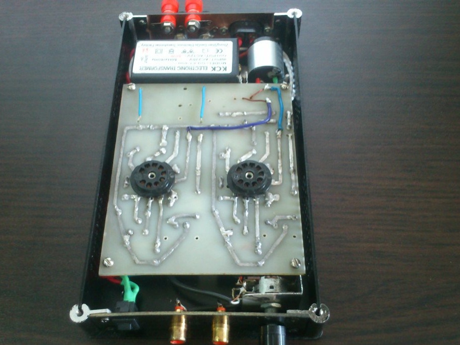
Food is organized as follows. Since the filament is designed for 6.3 volts and the transformer produces 12 volts, it was decided to connect the two filament parts of the lamps in series, the high voltage frequency for supplying the filament for the lamps does not matter. Power is supplied directly from the electronic transformer. For the anode power of the 6F5P lamp, a voltage of 220 - 300 volts is required. To obtain this voltage, a non-standard method was used. Background: during the experiments with one of the electronic transformers, it “exploded”, but the output transformer remained intact. It was finalized, the old secondary winding was removed, the primary winding was winded up with a thin MGTF wire using a shuttle to fill. And the former secondary winding with the same number of turns as before was wound with a PEL-0.8 wire over the primary one. The former secondary winding became primary and is connected to the output of an electronic transformer. At the output, a voltage of 250 volts of alternating current was obtained. After installation, it was decided to test the concept in general, and in order not to bear the risk, use cheap Chinese transformers for radio points as output transformers. Here is the first stand:

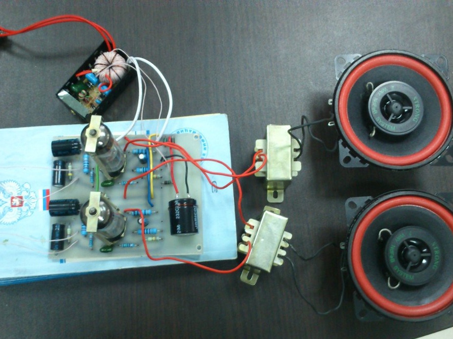
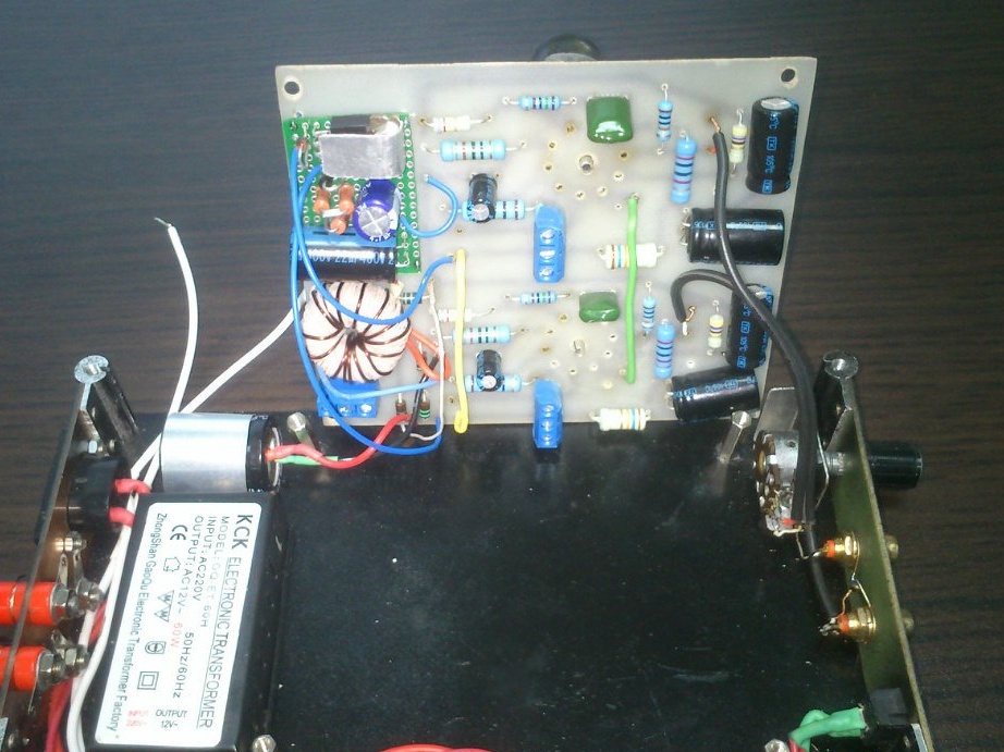
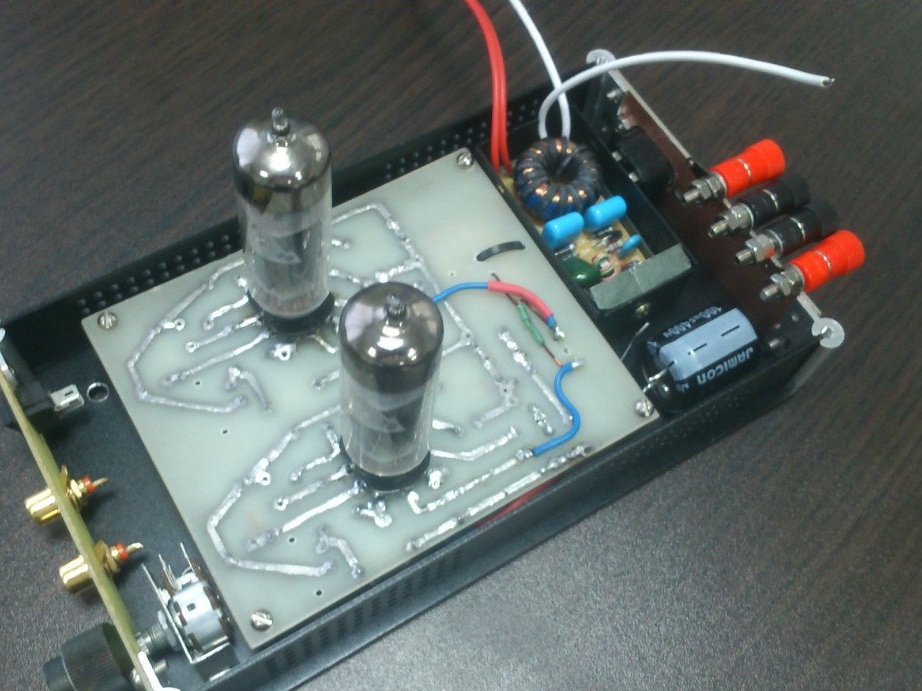
The electronic transformer device is clearly visible. During listening, the background of the alternating current was detected, the oscilloscope set its frequency to 100 Hz, i.e. the doubled frequency of the alternating current network. After researching the Internet, a circuit of the so-called “electronic choke” was found, it was made on an additional breadboard and installed after the rectifier. After installing it, the background disappeared. In general, the amplifier was not heard turned on or not turned on even at maximum volume. The electronic choke circuit is very simple:

The installed circuit board can be seen in the upper left corner of the circuit board (green, the transistor is mounted on a makeshift radiator). After listening and eliminating the background, the output transformers were replaced and installed in the final version. The result did not disappoint.

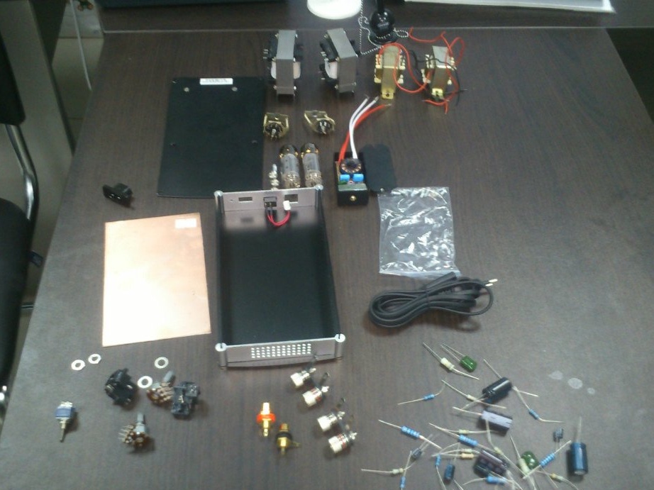
And now the manufacturing steps: collecting parts:

Preliminary prototyping:

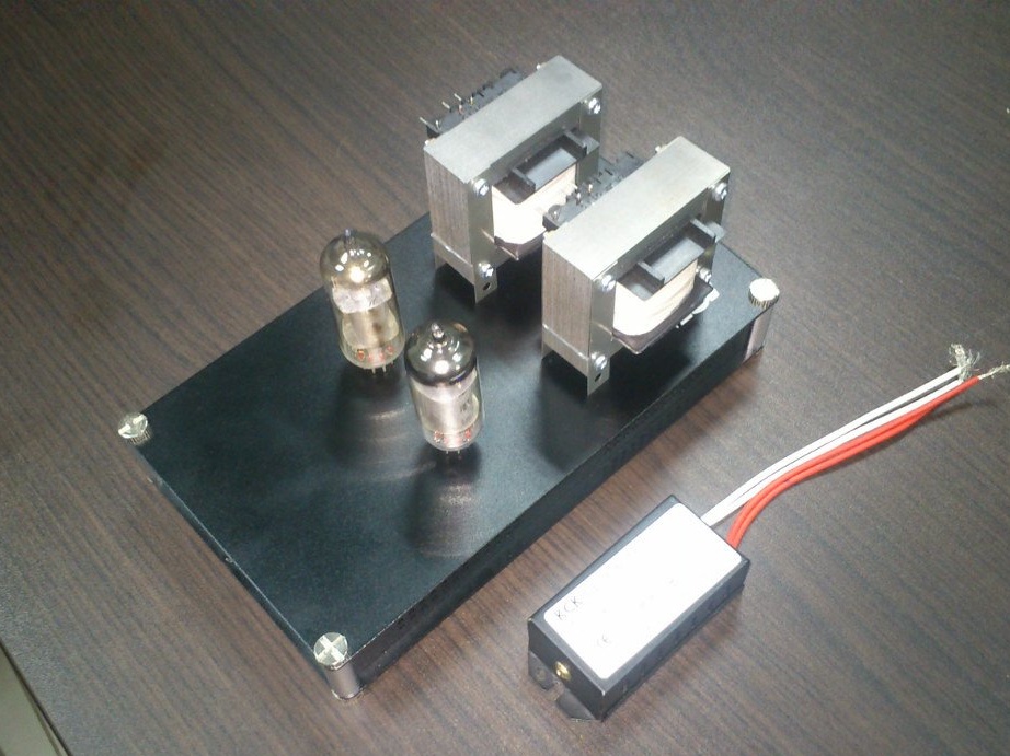
Prototyping showed that the project can be implemented and has the right to life.

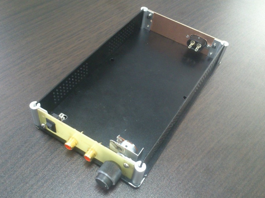
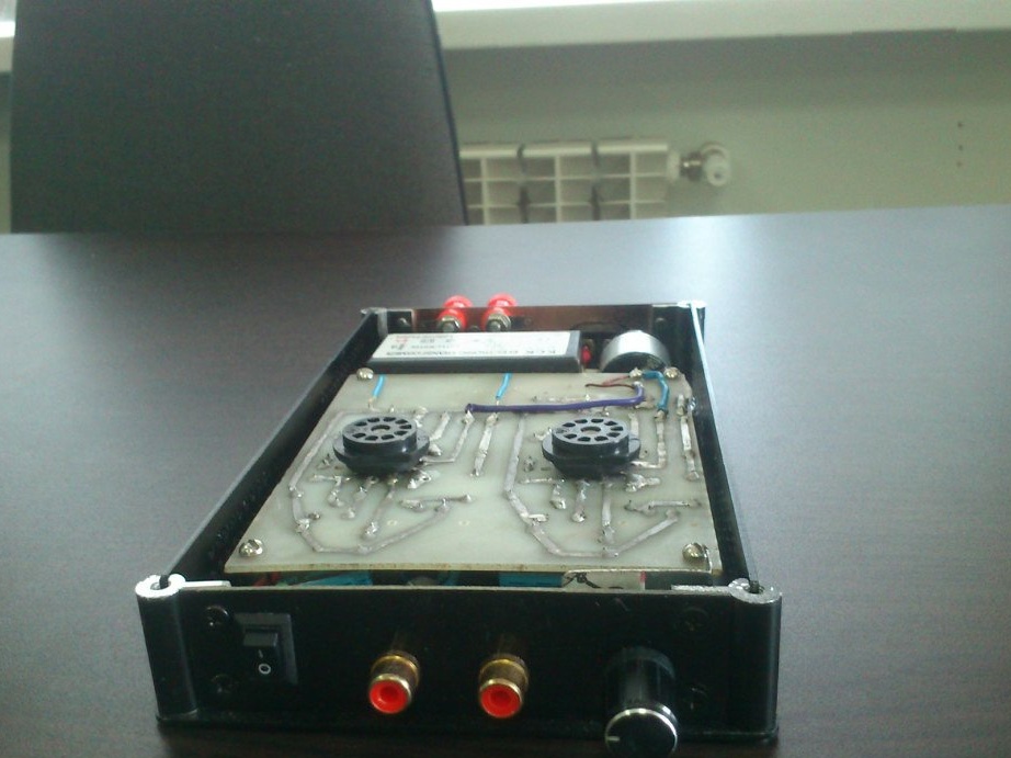
Beginning of the manufacture of the case:

Mounting:


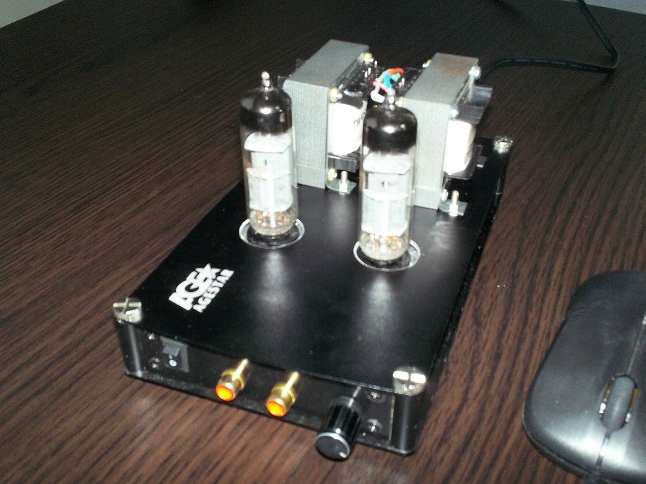
And the final version:


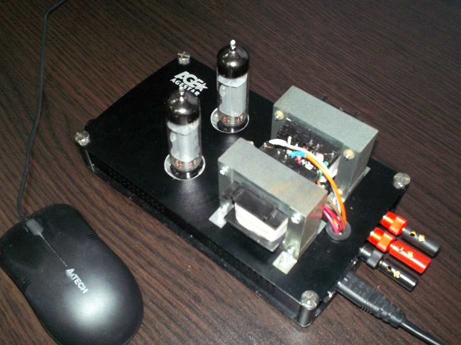
The amplifier is used in conjunction with the 20 Watt RFT brand GDR speakers, fully shakes them and has bright bass and a balanced frequency range.

Suitable for topic

Related topics

Add a comment

    • smilesmilesxaxaokdontknowyahoonea
      bossscratchfoolyesyes-yesaggressivesecret
      sorrydancedance2dance3pardonhelpdrinks
      stopfriendsgoodgoodgoodwhistleswoontongue
      smokeclappingcraydeclarederisivedon-t_mentiondownload
      heatirefullaugh1mdameetingmoskingnegative
      not_ipopcornpunishreadscarescaressearch
      tauntthank_youthisto_clueumnikacuteagree
      badbeeeblack_eyeblum3blushboastboredom
      censoredpleasantrysecret2threatenvictoryyusun_bespectacled
      shokrespektlolprevedwelcomekrutoyya_za
      ya_dobryihelperne_huliganne_othodifludbanclose
43 commentary
Author
Photos, wiretaps

and further
Author
Passed wiretapping at the fanatic of sound. Used expensive cords and speakers Kudos C20. The sound was shocking. He will soon share his impressions here.
Yes, it’s fun, but many have a completely rational physical explanation, it’s just not worth bringing any principles to insanity.
R555
experts have their own measurements, soft sound, for example, they spat on the SOI
I listen to the sound with my ears, and not with instruments, respectively, and the evaluation criteria are not% and coefficients, but better - worse, like it - don't like it! nea yes
Quote: R555
Once repaired by a German TV set, it seems Blaupunkt. So there were lamps and transistors and microcircuits in it.
Far found. )) Everything was in our ULPTSTI: lamps, transistors, and ICs, the latter being both hybrid and monolithic.
Korolev, the experts have their own standards, the softness of the sound, for example, they spat on KNI, well, if it's not 10%, of course.
I remember reading somewhere. Compare the best CD player and Indian (for some reason) vinyl. And they determined that Indian sounds better. By the way, several dozens of old Soviet lamps were presented to me recently with a laugh, they say play with them. There are lamps! 954 and other years. And I put them aside, maybe I’ll collect them on them and put them on the site. And the funny thing is, it will work on batteries, but not on such as before (I'm talking about anode, glow). Those who practice remember how the transition to transistors took place throughout the world. Once repaired by a German TV set, it seems Blaupunkt. So there were lamps and transistors and microcircuits in it.
R555
fan of the sound High End, then 0.05% can and hear
As has been repeatedly stated here, SOI is not the most important component of sound! With expert listening, preferences are usually given to the VLF tube, with a THD an order of magnitude higher! yes
Of course, such a small SOI will not give any laptop. Moreover, show the meter itself to measure it, at least name the brand. I collected meters and had industrial ones. If the meter also provides such accuracy in the entire audible range, at least the Nobel Prize will be given, rather the Shnobel Prize. For information. If you have the most musical ear, music lover, fan of High End sound, then 0.05% can hear it. I have such friends, they connect everything with gold-plated wires, even the speakers !!! They think that microwave currents are going by their surface.
By the way, do not forget about speaker distortion.
As for the euphonies, distortions are not limited to Kni; there are other parameters, both objective and subjective (where without them).
Guest Vladimir
harmonics from laptop, computer, etc. carriers 0.0001% maximum
Did you measure it yourself? If not, I would like a link to the source of information! scratch
Guest Vladimir
The contradiction itself, harmonics from a laptop, computer, etc. of carriers, 0.0001% maximum, are the harmonics of a lamp in the final stage 0.3% at best ... Where is the logic? The even harmonics of the final stage supposedly adorning the sound, there are still distortions, where is the fidelity in the sound? To which is all aspiration so? Enough for the young people to powder their brains! A tube amplifier of high fidelity, beyond the power and can not afford the experienced and living in prosperity .....
Author
I liked your work. I read it very carefully, I think how you will organize the power of the lamps ... Have you tried to shoot the frequency using instruments? I have no doubt about the lamps, but the output trance on the bottoms and tops can overwhelm the frequency response. [/ Quote]
By the way, I described in detail the power of both the filament and the anode. If necessary, I’ll write in general in detail. I will draw and take a picture of this.
Author
Quote: R555
I liked your work. I read it very carefully, I think how you will organize the power of the lamps ... Have you tried to shoot the frequency using instruments? I have no doubt about the lamps, but the output trance on the bottoms and tops can overwhelm the frequency response.

There are two lamps in this project. The heat of each 6.3 V. I connected them sequentially and directly to the output of the electronic transformer. Judging by the transformer passport that I took to Istok-2, their range is 23 Hz -22 kHz. Somewhere they work. If you apply the Maranz trans, you can get 12-60 kHz. Each of 1000 cu
I liked your work.I read it very carefully, I think how you will organize the power of the lamps ... Have you tried to shoot the frequency using instruments? I have no doubt about the lamps, but the output trance on the bottoms and tops can overwhelm the frequency response.
ino53
Do not believe those who say that it is not given to people to hear
He who has the Ear, let him hear! goodgood
A bit of humor (no offense!) xaxa
Something does not work to hide the text, moderator, help. this
Attention! You do not have permission to view hidden text.
. [/ hide]
Author
Quote: ino53
Quote: Nikolai Ivanovich
... There is harmonic up to the output transformer, I think from a UPS of about 100 kHz. After the trance, she is gone ....

This means that the UPS still affects the signal, noise. this In this circuit, the TVZ inductance cuts off the noise; in a transformerless circuit, the noise would go to the acoustics.

Harmonics are not big, I did UMZCH on TDA 7294 with the same UPS, only with different transformer trimming parameters. works fine.
Quote: Nikolai Ivanovich
... There is harmonic up to the output transformer, I think from a UPS of about 100 kHz. After the trance, she is gone ....

This means that the UPS still affects the signal, noise. this In this circuit, the TVZ inductance cuts off the noise; in a transformerless circuit, the noise would go to the acoustics.
Dependence K of the transfer of the divider on the input (counting from below) part of the variable resistor:
Quote: Nruter
I didn’t ask anything about it.
It describes the principle of changing the characteristics of a variable when a constant resistor is included in parallel.
Quote: Nruter
The resistor of the passive volume control should have an inverse logarithmic relationship, i.e. indicative.
Of course, this is a classic solution.
Quote: Nruter
Why not make a grid connection with the mass through a 100 kΩ resistor, but with a signal level regulator through a capacitor. At the same time, they would also correct the frequency response. This is what I am writing about.
Again - a classic. But for some reason Manakov in all his amplifiers makes just such an input, he does not explain the reason anywhere.
Quote: Ivan_Pokhmelev
About the characteristic of resistance look here:

I didn’t ask anything about it.
The resistor of the passive volume control should have an inverse logarithmic relationship, i.e. indicative.
Why not make a grid connection with the mass through a 100 kΩ resistor, but with a signal level regulator through a capacitor. At the same time, they would also correct the frequency response. This is what I am writing about.
I’ll tell you how I went about to get the characteristic B on the type A type SP3-23 type variable group A. It was in the second half of the 80s, with the details like the then fashionable slider alternators it was tense, and it’s good if it was possible to get any group at all. I then managed to buy 8 pieces per 10 kOhm of group A. I decided to put 6 pieces on the graphic equalizer, and the remaining two to be made by volume controls (although they were dual, I wanted to adjust each channel separately). Of course I do not advise repeating, but I will share my experience. So, I took apart these resistors, and with the help of a simple pencil (as in the movie "Red Tent"), an eraser and a "model" circular variable converter, I got the necessary characteristic with an impedance of 5 kOhm (I don’t remember more precisely). "Set" on four points of position, applying strokes with a pencil or erasing them. I worked with the amplifier until the mid-90s, until I left it at the Young Technicians Station, when I changed jobs, I do not know his further fate.
In the late 70s and early 80s I had a Nota-M tape recorder, so this (at 6F5P) amplifier fit neatly inside the case. The installation was really mounted, but it worked perfectly.
About the characteristic of resistance look here:
RL 1995/04, Semenyuta N. "Logarithmic variable resistors from linear."
Quote: Nruter
I have never seen such a connection.
Look at the classic Manakov's amplifier repeatedly repeated by thousands of people. This is his scheme.
Quote: Nruter
Input impedance is not formed.
Not the input impedance, but its characteristic.
Quote: Nruter
The rustling depends only on the quality of the variable resistor.
Not only. Of course, if the quality of the alternator is high and it is guaranteed that it does not allow a break, then an additional resistor may not be needed. And if the quality is worse, then with each micro-break of the connection of the slider with the “horseshoe” the grid will hang “in the air”, which, given the large input impedance, will lead to the possibility of interference.
Author
Quote: Nruter
Quote: Nikolai Ivanovich
Check concept

What is the point of a 100 kΩ resistor connected to the grid of the triode part of the lamp?

In the next homemade product I will not immediately install it, or install it in one channel. Then I will tell you what happened.
Author
Quote: ino53
It would be interesting to see the waveform, a sinusoid. Why it is interesting - as the combo Venta picked up with the UPS, so there, with some combinations of the positions of the regulators, some kind of "dregs" got into the signal. Gold-eared Labuhs were unhappy. I did not find the reason. scratch On the other hand, in Beringers with their class D amplifier, the UPS is just that. goodgood

the waveform up to 3 watts is symmetrical, then the shelves begin. For some reason, up to 4 watts is not reflected by ear. There is a harmonic to the output transformer, I think from a UPS of about 100 kHz. After the trance, she is gone. Of course, the High Ends probably already ordered my kill, however, the sound of even a simple circuit on a printed circuit board and a switching power supply is beyond praise.
Author
Quote: Nruter
Quote: Nikolai Ivanovich
Reduce rustling, plus form input impedance.

The rustling depends only on the quality of the variable resistor. Input impedance is not formed. I don’t understand the meaning of connecting the grid to the mass when the resistor slider is at the bottom (according to the diagram). I started to make tube home-made products in 1975, but I have not seen such a connection anywhere.

I just took the classic circuit, and was not disappointed.
Quote: Nikolai Ivanovich
Reduce rustling, plus form input impedance.

The rustling depends only on the quality of the variable resistor. Input impedance is not formed. I don’t understand the meaning of connecting the grid to the mass when the resistor slider is at the bottom (according to the diagram). I started to make tube home-made products in 1975, but I have not seen such a connection anywhere.
It would be interesting to see the waveform, a sinusoid. Why it is interesting - as the combo Venta picked up with the UPS, so there, with some combinations of the positions of the regulators, some kind of "dregs" got into the signal. Gold-eared Labuhs were unhappy. I did not find the reason. scratch On the other hand, in Beringers with their class D amplifier, the UPS is just that. goodgood
Author
Quote: Korolev
Nikolay Ivanovich
this is one of the smallest tube amplifiers
I think that I will not be mistaken if I assume that it sounds much better than most (if not all) standard, and even expensive computer (and not only) systems! goodgood

It really sounds better than all standard PS systems and most common systems. Loses only in power to them.But, really enough. Even for scoring movies with explosions is enough. In terms of reliability, many details of classical music appear, each instrument can be distinguished, which was not noticeable on the Pioneer A-10 class amplifier, of course, it is a worthy amplifier, but for another.
Author
Quote: Nruter
Quote: Nikolai Ivanovich
Check concept

What is the point of a 100 kΩ resistor connected to the grid of the triode part of the lamp?

The guys below said correctly. Reduce rustling, plus form input impedance.
It is possible, in order to correct the adjustment characteristic, from type A to make type B, or type B to make it even more gentle at the beginning.
They don’t look for good from good .;) If Manakov did so, then it is better to repeat his version.
The point, I think, is to exclude an open circuit when moving the potentiometer engine when adjusting the volume, as a result to reduce rustling when adjusting.
Quote: Nikolai Ivanovich
Check concept

What is the point of a 100 kΩ resistor connected to the grid of the triode part of the lamp?
Nikolay Ivanovich
this is one of the smallest tube amplifiers
I think that I will not be mistaken if I assume that it sounds much better than most (if not all) standard, and even expensive computer (and not only) systems! goodgood
Author
Quote: Guest Andrey
What's the point ??? So for fun?

Check the concept and your strengths. Agree, this is one of the smallest tube amplifiers.
Guest Andrey
What's the point ??? So for fun?
Try to find and listen to at least the simplest tube amplifier! goodgood
Guest Andrey
What's the point ??? So for fun?
Author
Non-isolated contacts of transformers - dummies. Everything else is shrink. For a laptop - because it’s small. I would do for the system unit, I would put TS-270 yes
Author
thank you for rating
By the amplifier itself. A normal classic tube ULF of the middle class, neatly made and correctly described.
The danger is the transformer contacts that are not closed from accidental contact.
And what does the laptop have to do with it? From another signal will not work? )))
Amplifier for laptop on radio tubes
Reminded "Jumble" - Watch Batteries

We advise you to read:

Hand it for the smartphone ...