
In this article, the author of the YouTube channel Radio-Lab will show how to assemble a simple subwoofer amplifier with unipolar power on a popular subwoofer. The amplifier is not complicated and performs its tasks. It can be used both indoors and in car. The power is not big, but for comfortable listening it is enough, and sometimes even a bit too much. If you do not rush and do everything correctly, then repeating the project will not be difficult. Try, collect and repeat.
It often happens that there is a subwoofer, for example, from a home theater, it is quite working, but an amplifier is needed for it.
A diagram of the future subwoofer amplifier is now in front of you:
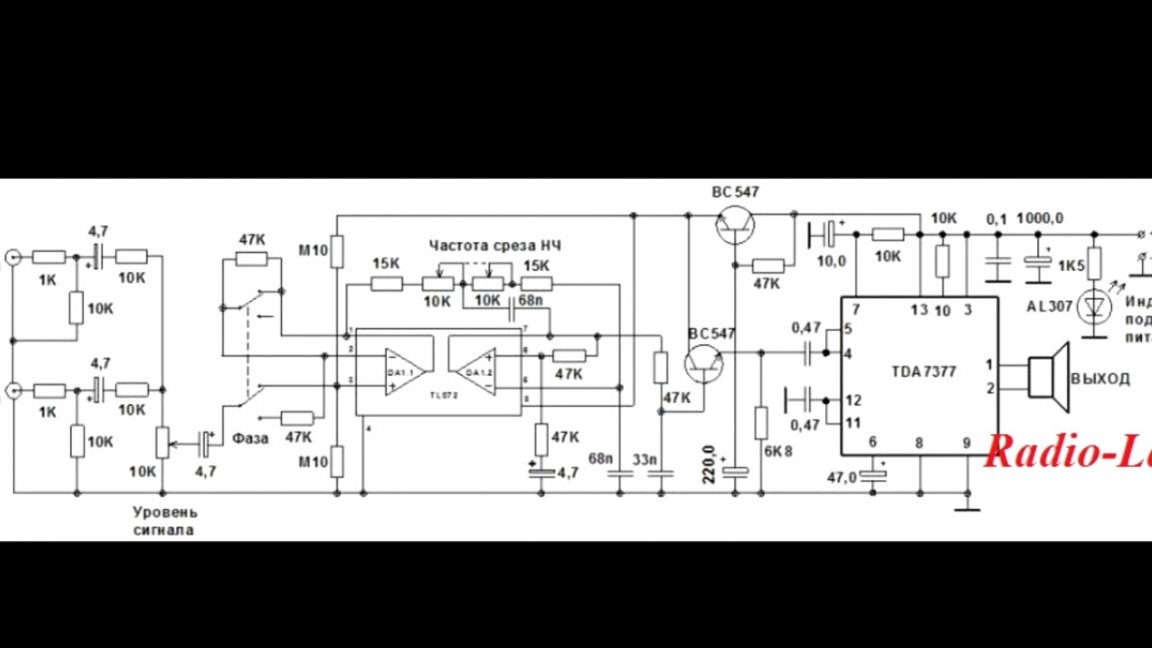
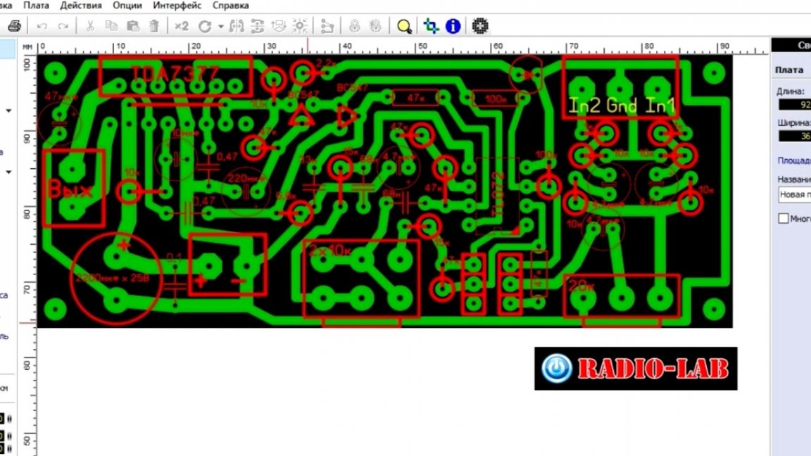
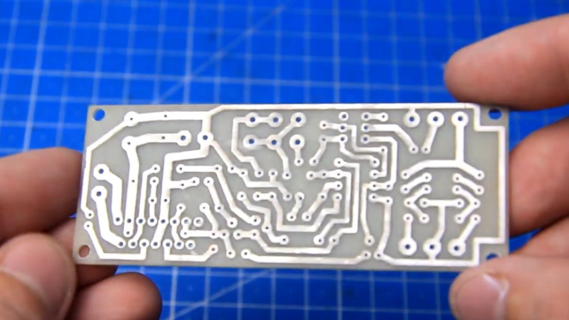
It contains all the necessary nodes and settings. This scheme was found by the author on the Internet. The amplifier board was not large, the dimensions were 92x36mm. You can download the board and amplifier circuit HERE.
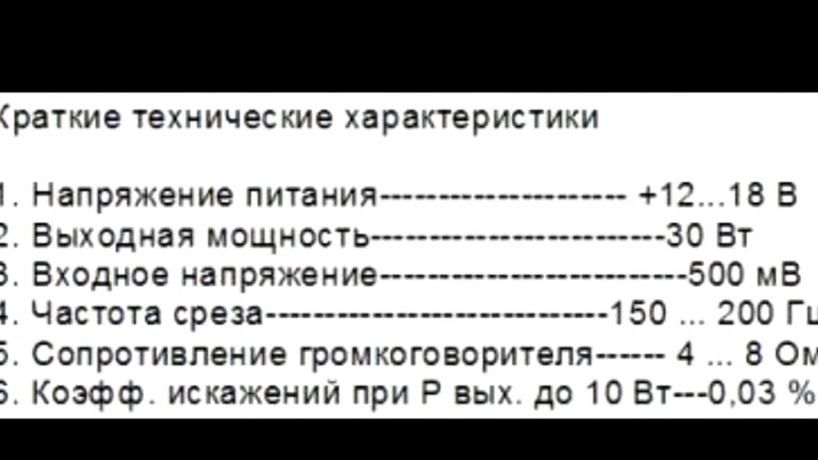
The image below shows the main characteristics of this amplifier.
All necessary details can be either on the radio market.
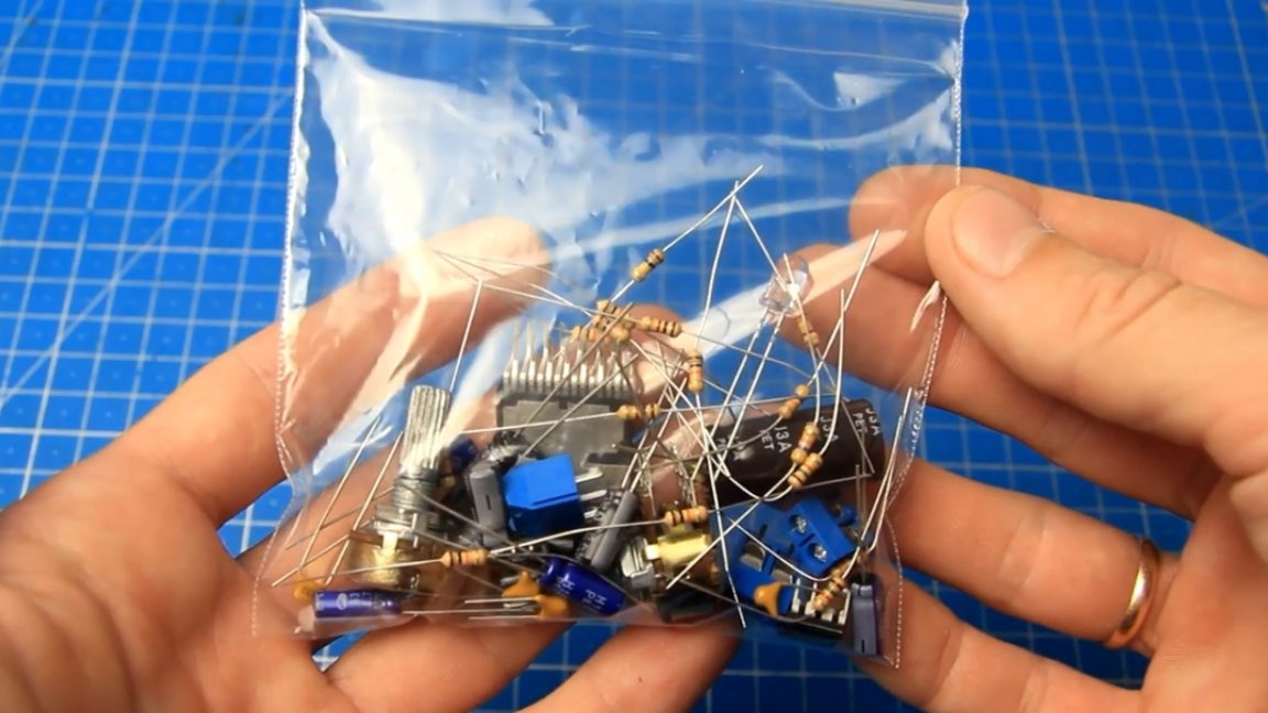
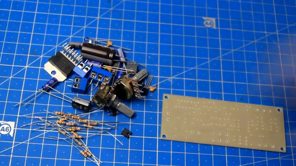
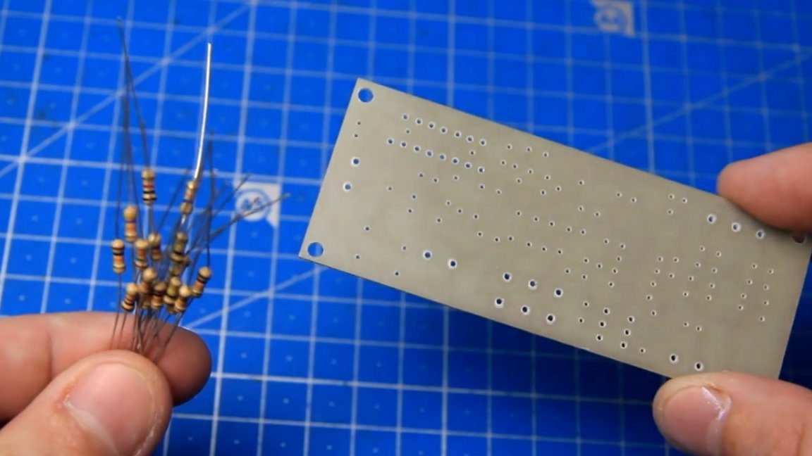
Built on the basis of the amplifier, this is an AV class amplifier. Here are all the necessary parts for assembling the amplifier, there are few of them, but at the same time there are not so few.
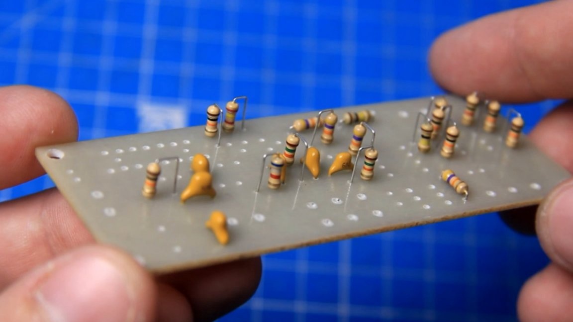
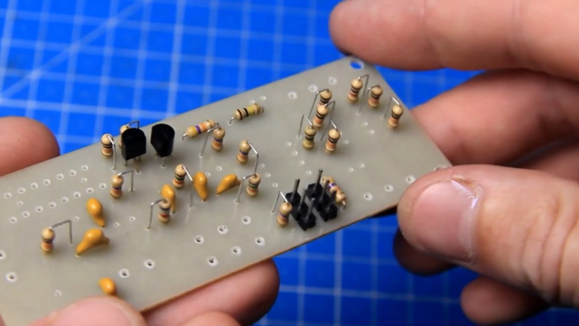
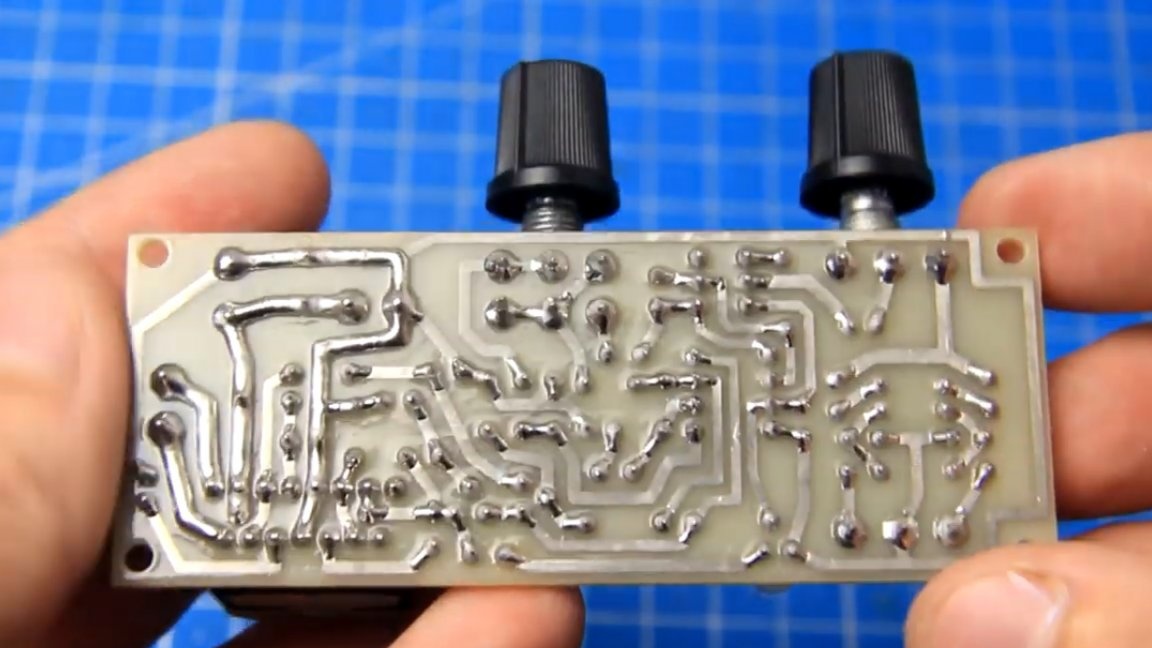
The board is made using photoresist. So, for the assembly, everything is there, let's collect it already. First of all, the author recommends soldering fixed resistors.
In order not to accidentally confuse their face value, you can use this:
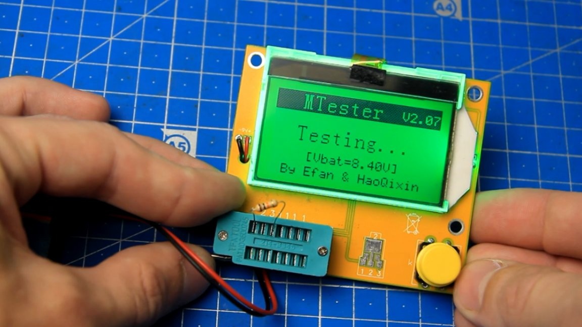
This device is able to measure the nominal value of the part and displays the result on the display. As you can see, it showed 10k, install the resistor in its place and fix the part using a soldering iron.
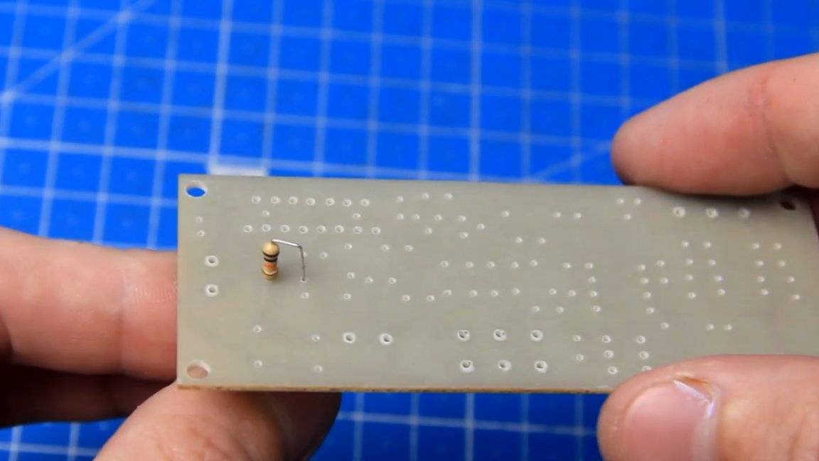
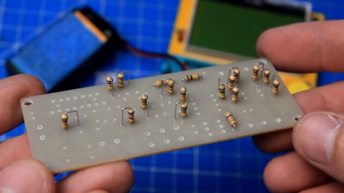
We do the same with the rest of the resistors. It is worth noting that some of them are installed vertically, and part - horizontally.
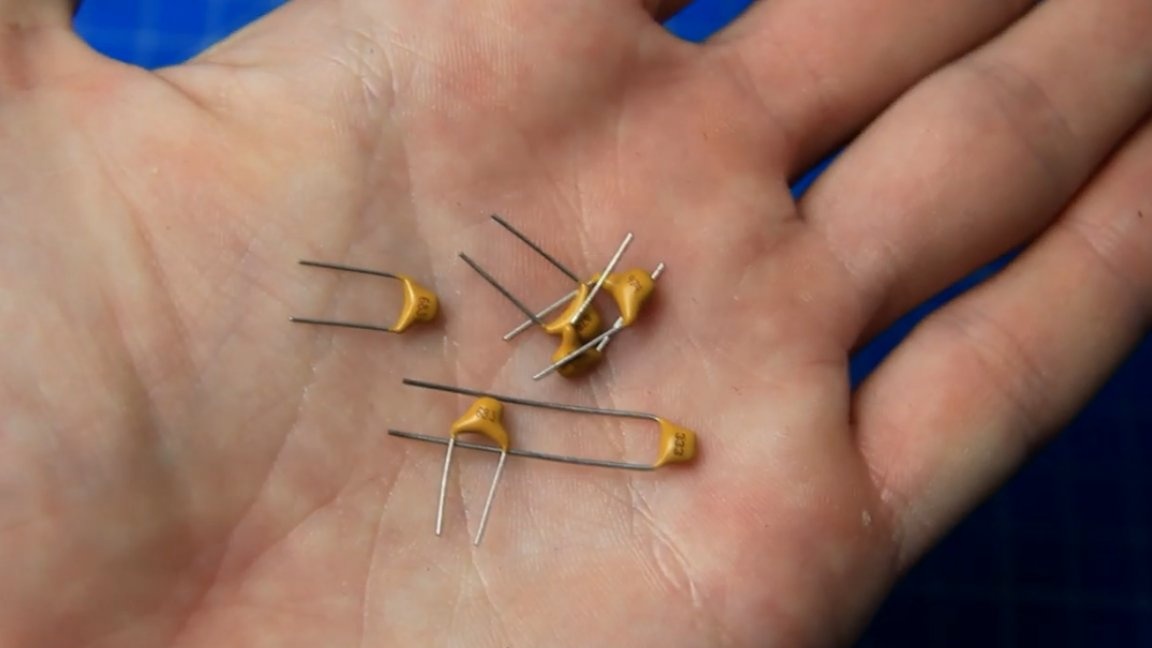
Next, we proceed to the installation of non-polar capacitors. Denominations are written on the case.
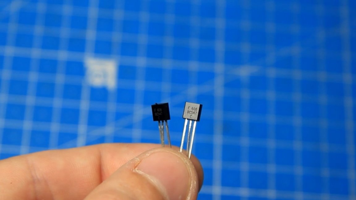
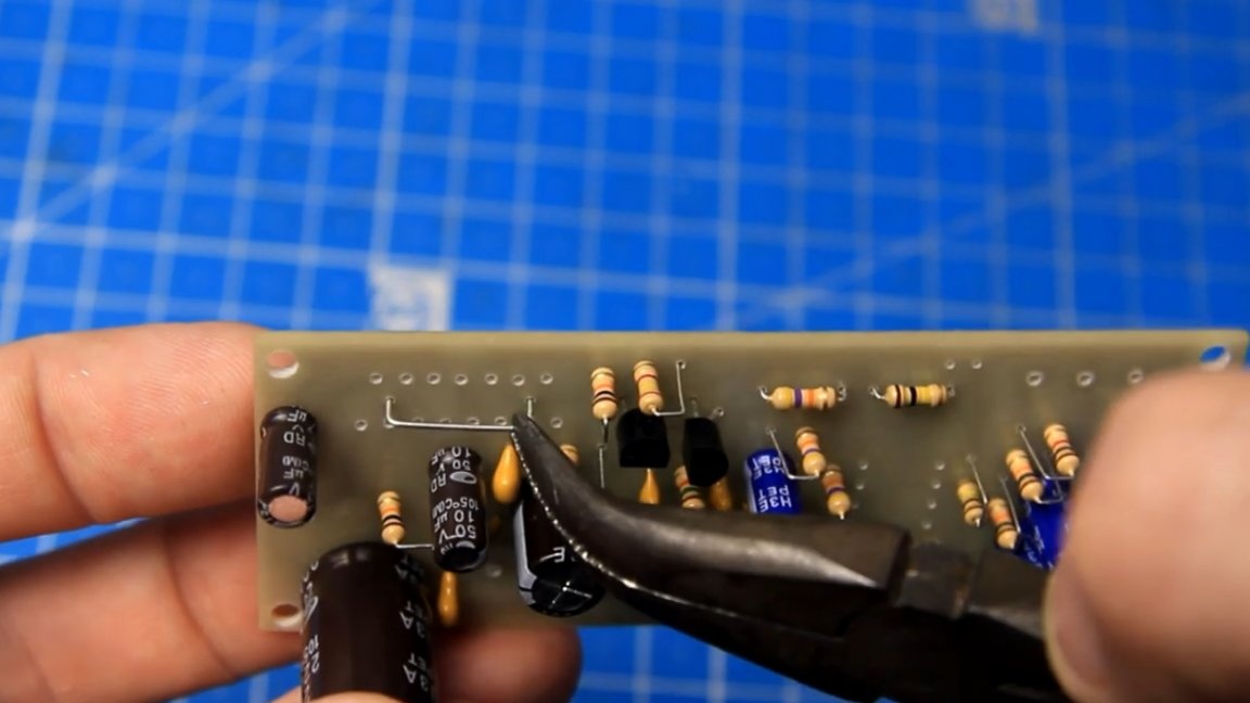
The amplifier has a pair of transistors. We put them on the board, as shown in the drawing, it is important not to confuse here.
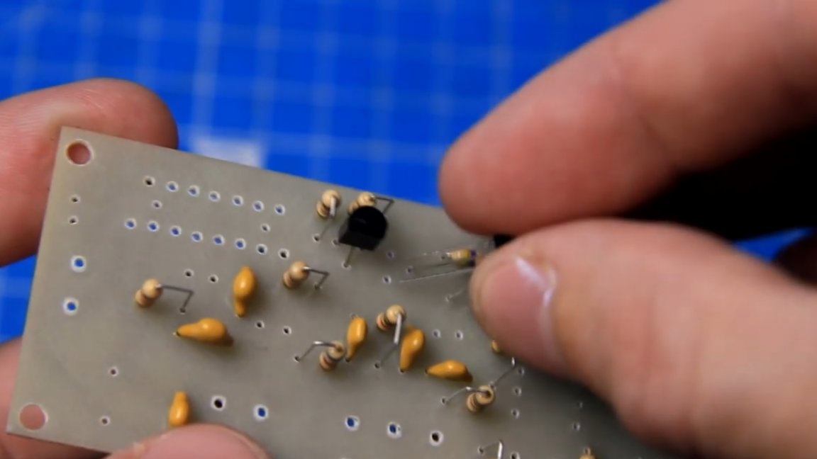
Now we need to solder these pins with a pitch of 2.5 mm.
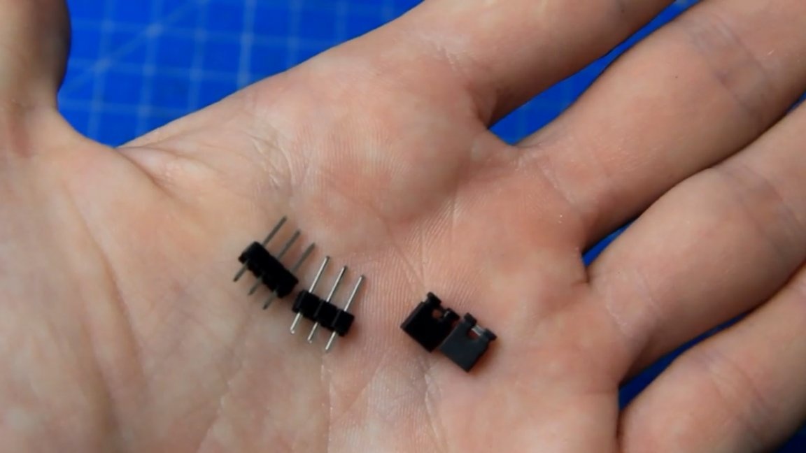
In the future, jumpers will be installed on them. They are sold like this:
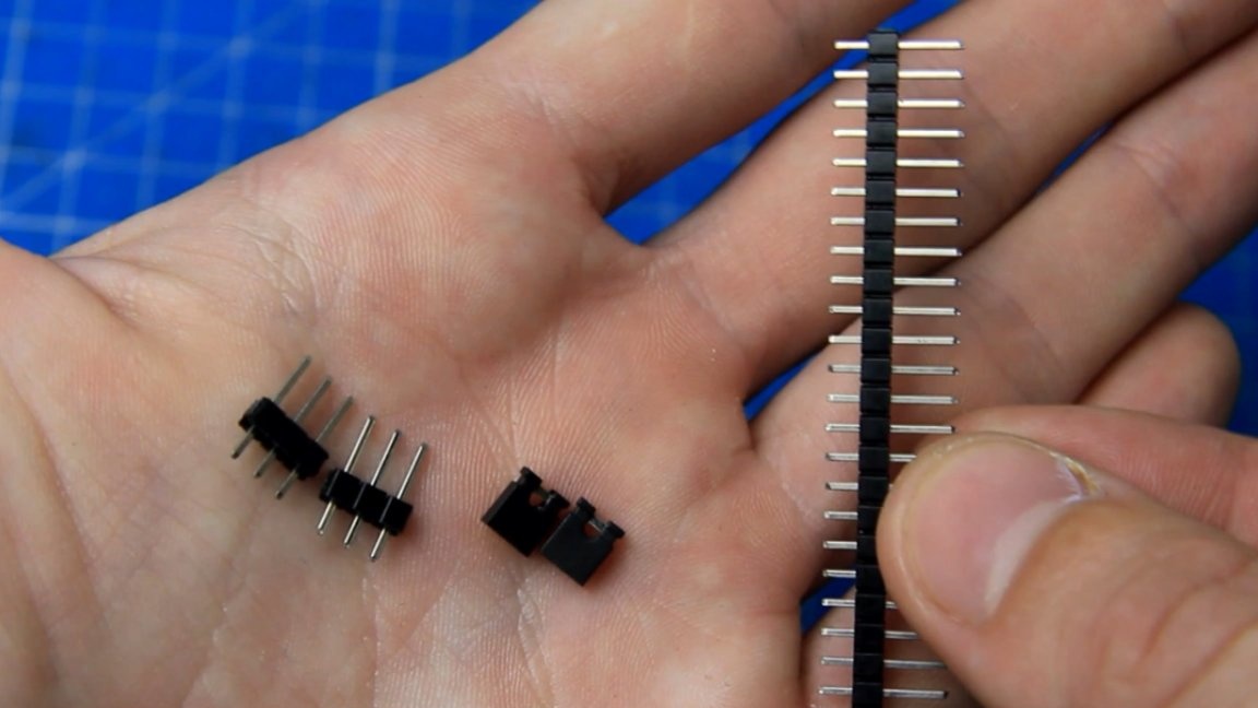
The right amount must be broken off. Next, on the sealed pins closer to the edge, you must put on two jumpers.
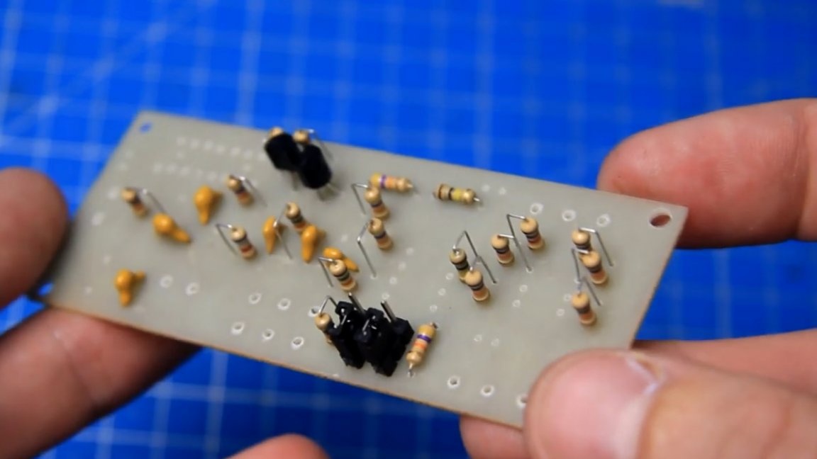
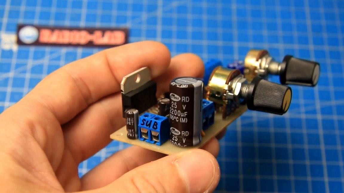
Now we proceed to the installation of polar (electrolytic) capacitors.
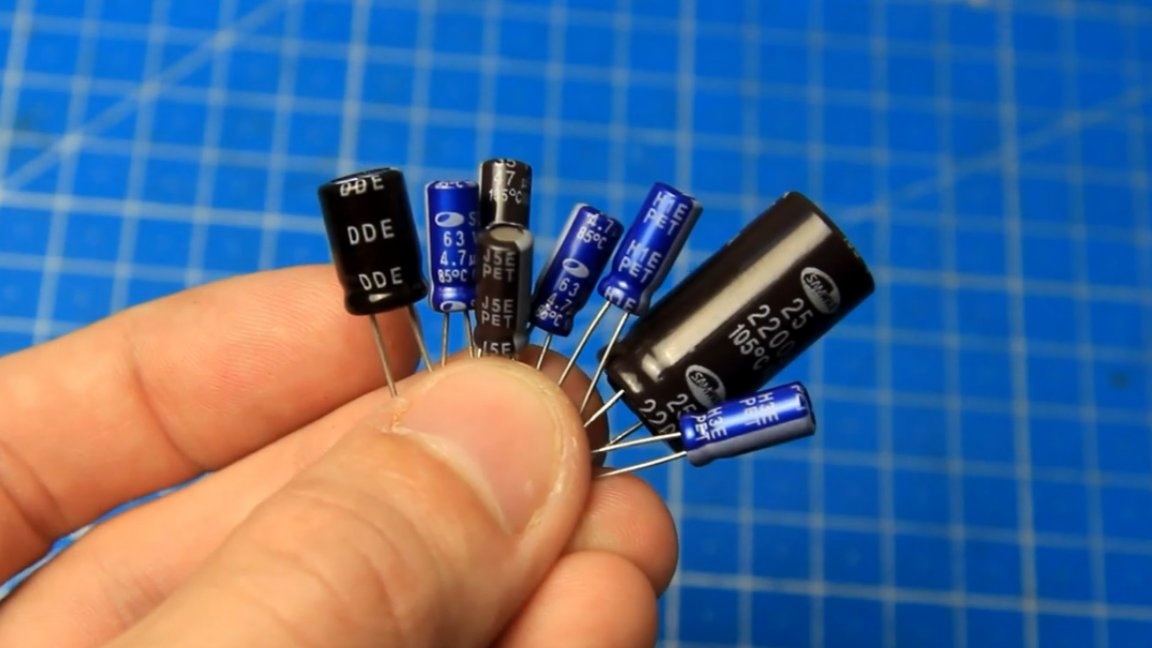
They must be installed carefully, always observing the polarity.The nominal and minus label is necessarily present on the capacitor housing. The voltage of the capacitors in this case is not lower than 25V. There should be one jumper on the board and its place - here:
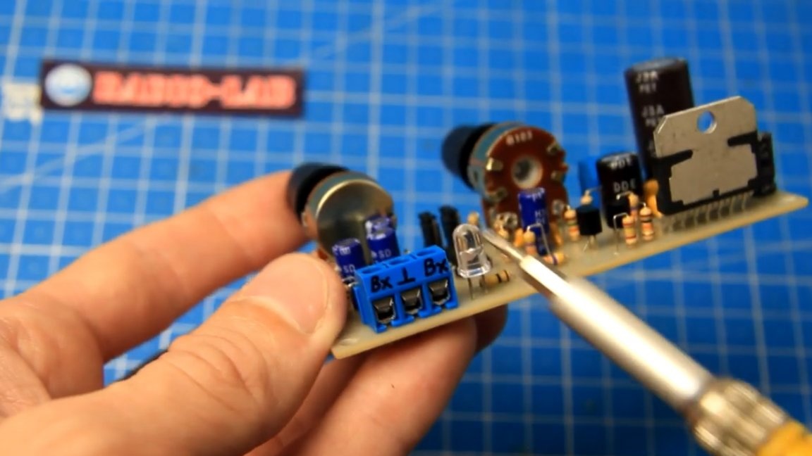
The LED (power indicator) must be installed here:
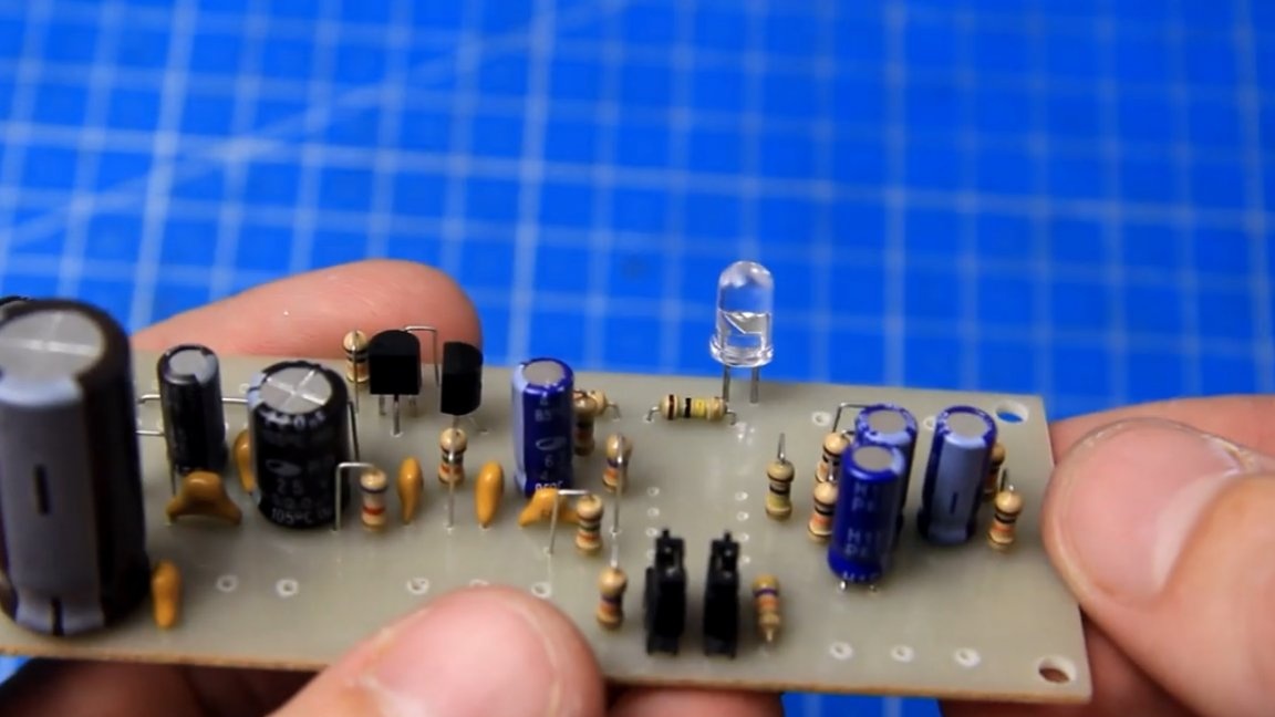
In this case, do not forget about the polarity, the corresponding minus mark is present on the case.
In this case, this operational amplifier is responsible for the cut of high frequencies, it must be installed by the corresponding label (key) on the case.
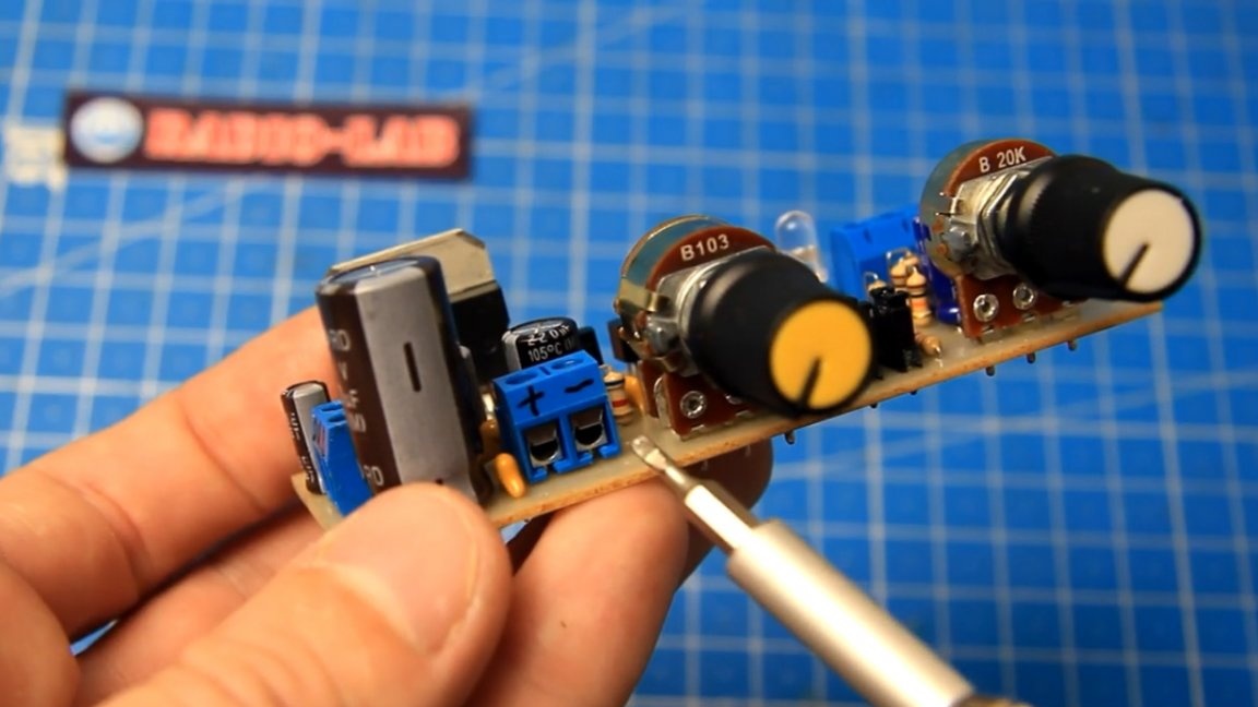
We will have two variable resistors, single and double.
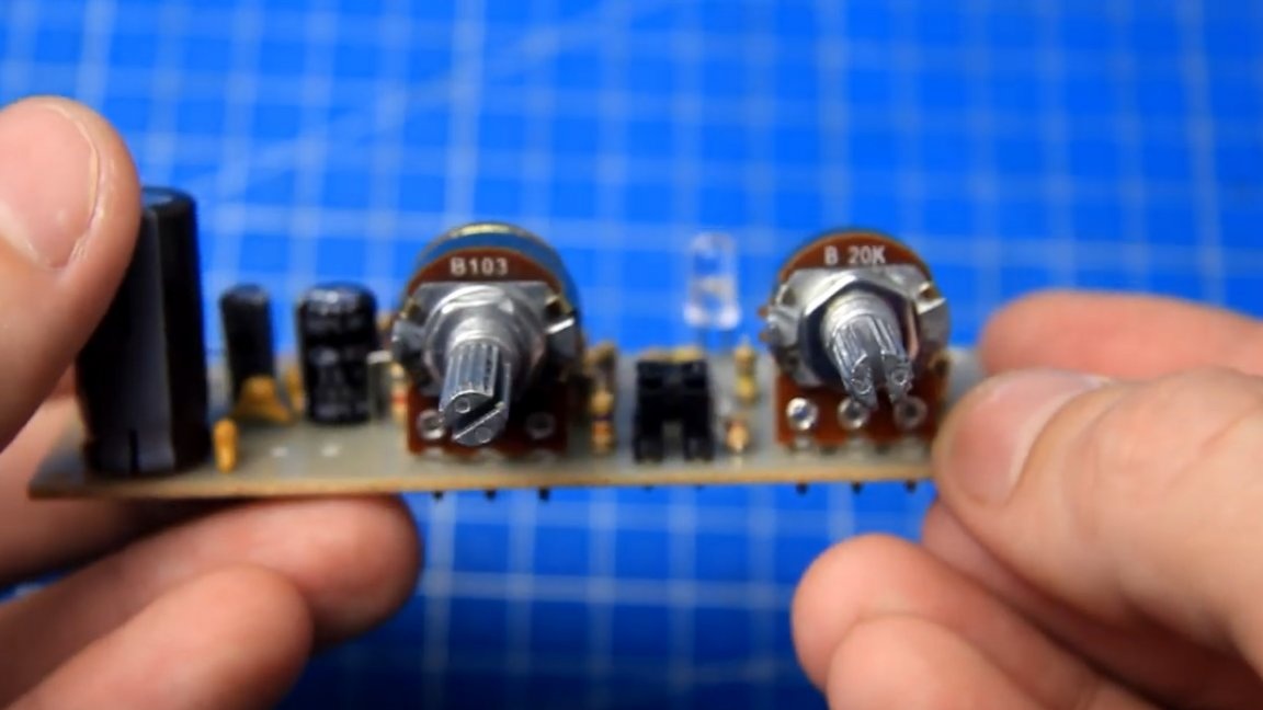
In order not to solder anything, there are screw terminal blocks on the board for connecting power, input and output.
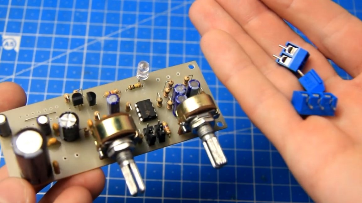
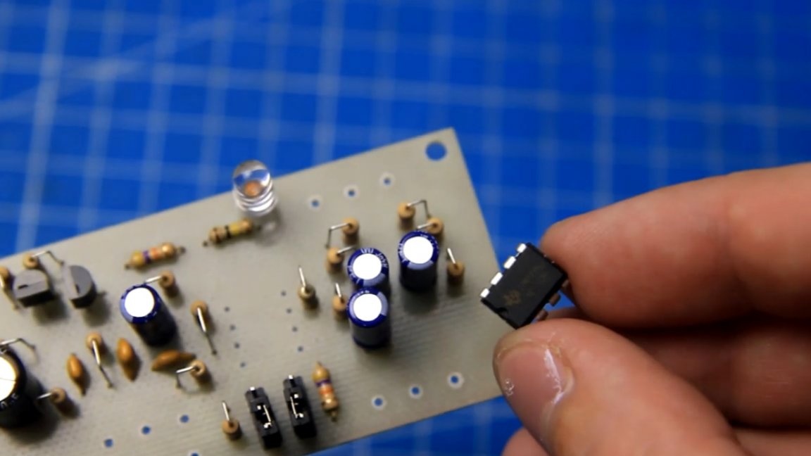
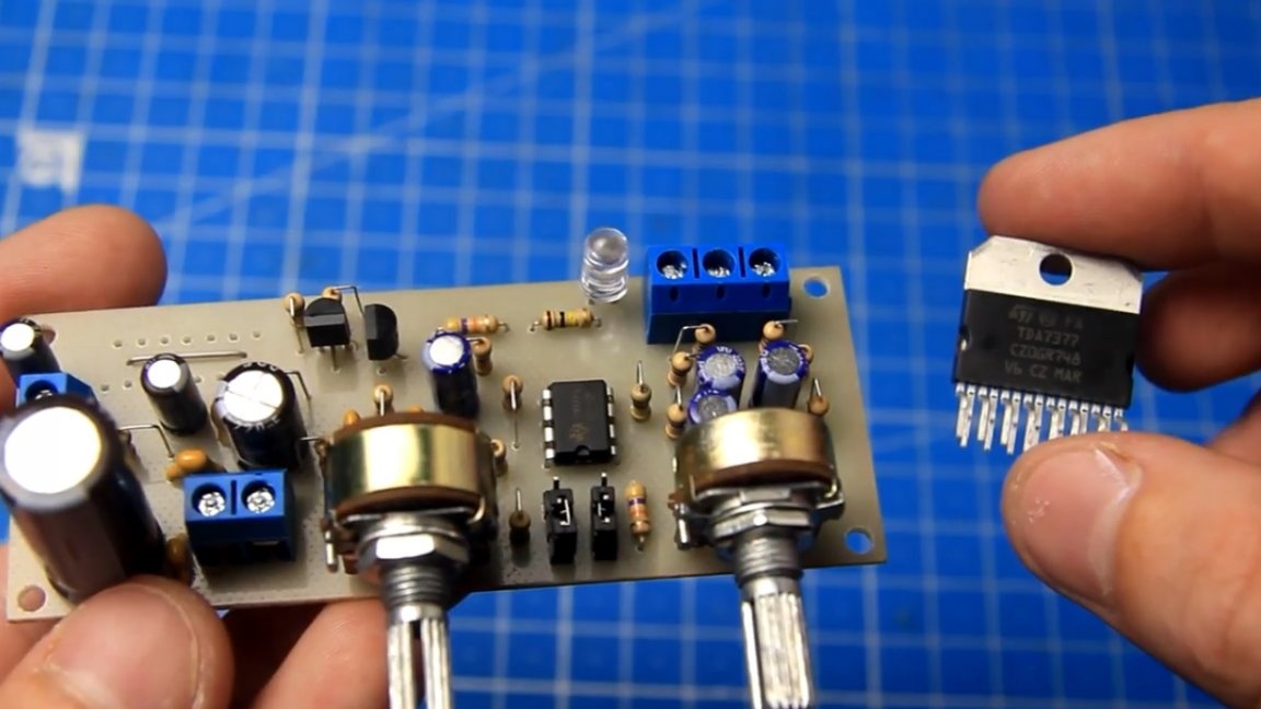
The project is almost ready, it remains to carefully install and solder the amplifier chip itself.
For ease of rotation, the author bought two handles that are worn on variable resistors.
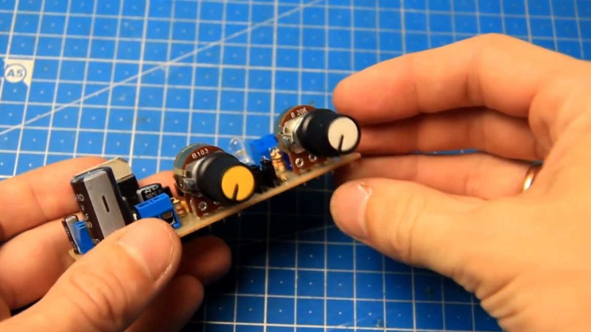
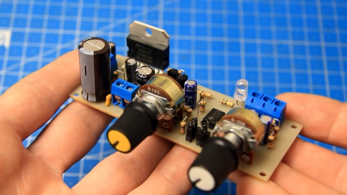
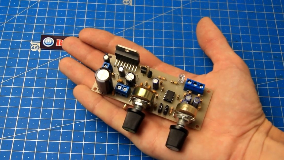
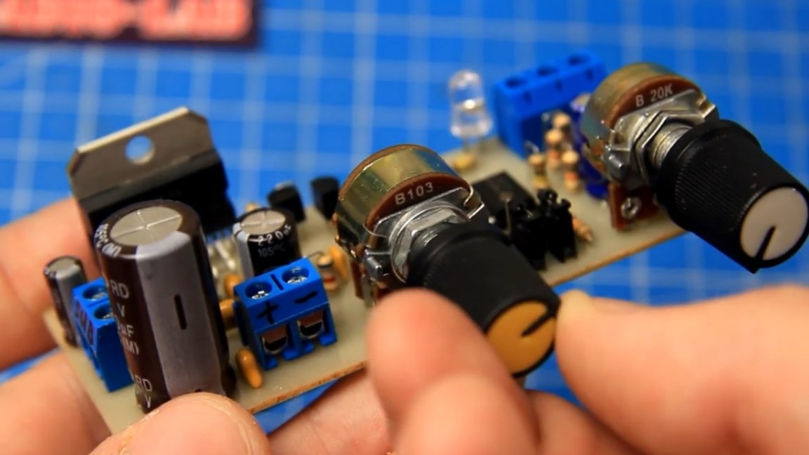
Assembly is fully completed. As a result, we got such a subwoofer amplifier:
The dimensions, as you see, are not large, everything is compact. The board must be washed and varnished.
The power supply and subwoofer output paths, where the largest currents will flow, it is advisable to further strengthen the solder.
The amplifier is assembled and looks like this:
Now for the connection. Here is the terminal block for connecting power, it is necessary to observe the polarity here.
This is the terminal block on which you want to connect the wires of the subwoofer.
And this one, with three contacts, an input terminal block, for supplying an audio signal from the device (phone, player, line-out of car radio, etc.).
Now for the adjustments. Using the first knob, you can adjust the bass volume if necessary.
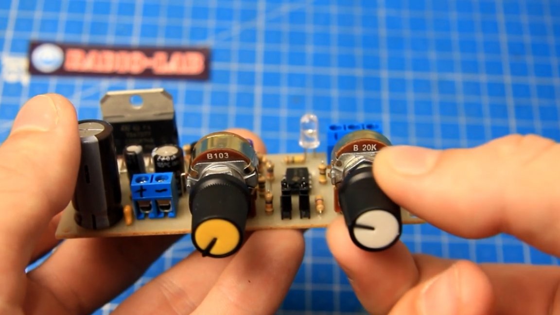
Jumpers allow you to change the phase of the signal by 180 degrees, which makes it possible to synchronize the subwoofer with the main acoustics, again, if necessary. Jumpers must be placed either closer to the edge or closer to the middle of the board. The second knob allows you to adjust the cutoff frequency.
Adjustment is present, but its range is not wide. Conventionally, this board can be divided into three parts: an adder, a low-pass filter and a sound amplifier.
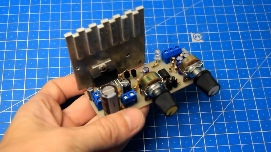
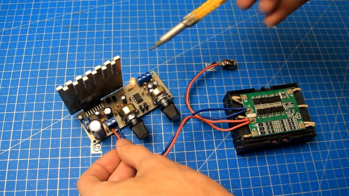
As mentioned above, this AV class amplifier will also heat up during operation. Therefore, it is necessary to add a radiator. For the test, the author took this, not a large radiator, but for normal cooling, of course, a larger radiator is needed.
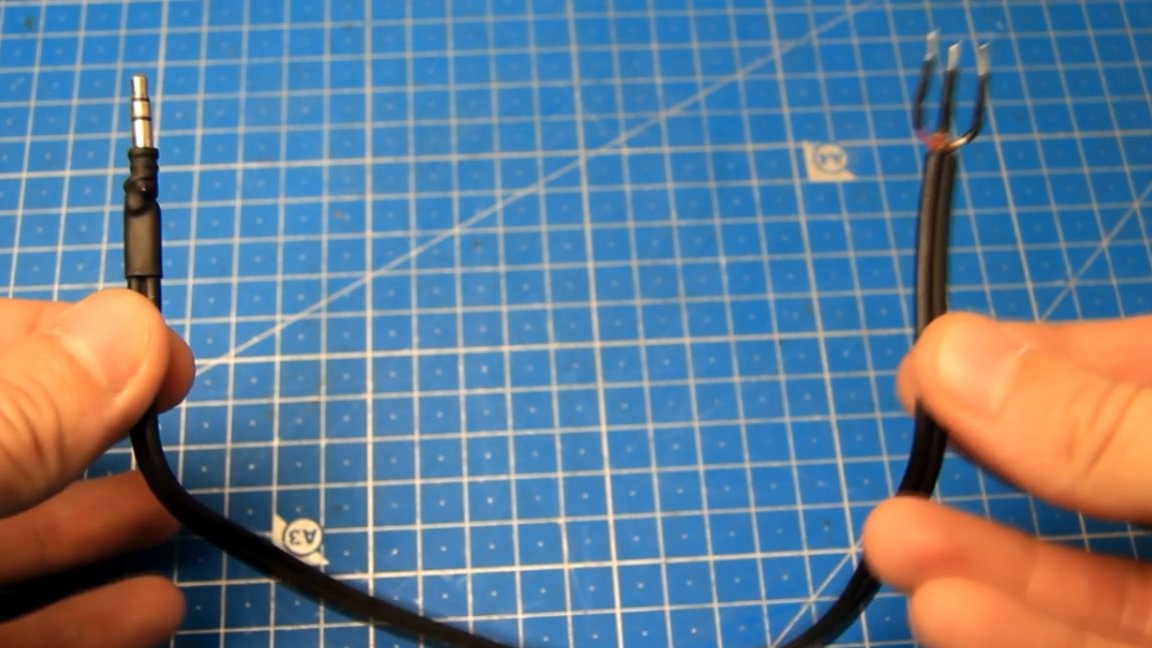
Such a shielded wire with a 3.5mm connector will be used to supply the sound signal.
To power the amplifier, you can use a battery with a voltage of 12V.
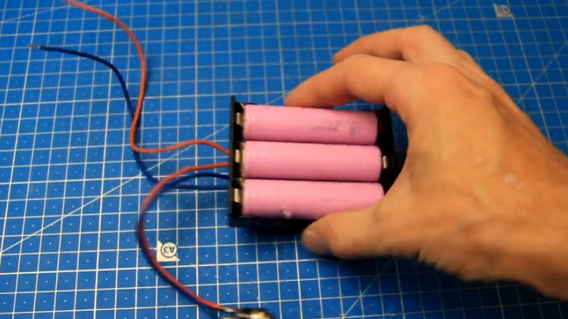
We connect the battery, be sure to observe the polarity.
As you can see, the LED is lit, so there is power. Excellent! Next, connect the input wire.
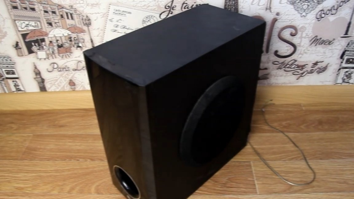
The test subwoofer will be like this, left over from the home theater.
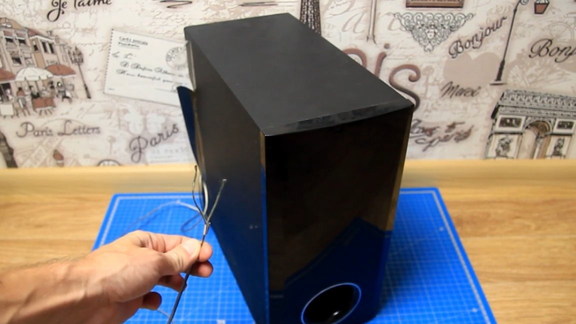
Connect the subwoofer wires to the amplifier output terminal block and connect the battery.
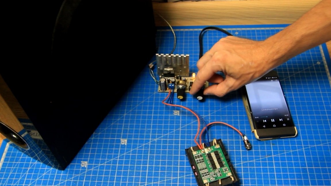
The smartphone will serve as the source of the test signal, connect it to the amplifier input and turn on the test track.
We try to rotate the bass volume level on the assembled amplifier, the subwoofer starts to play, the amplifier is working, it is audible that only low frequencies are playing, the filter on the amplifier is working and, accordingly, only them are left. The cutoff frequency is adjustable, but as mentioned above, the adjustment range is not large.
Further, the author assembled such an audio system 2.1 with a subwoofer:
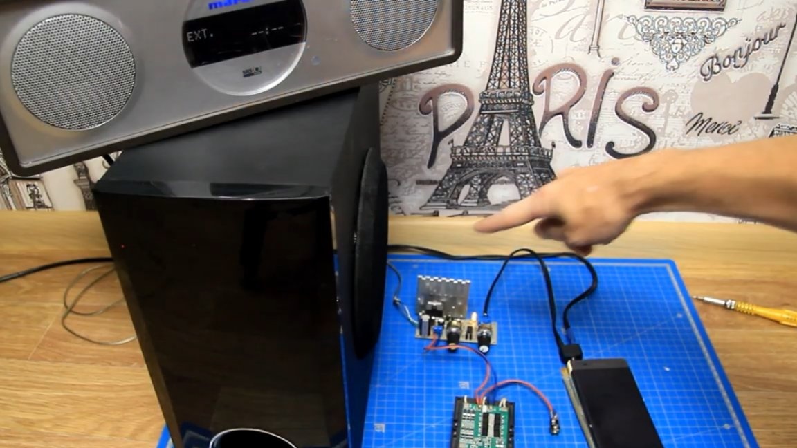
Instead of a battery to power the amplifier, you can use a suitable power supply unit from an AC 220V. We turn on the test track and try to rotate the volume level. More details in this video:
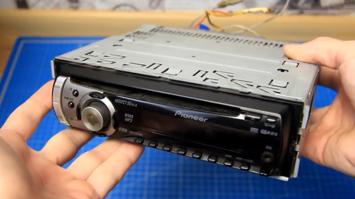
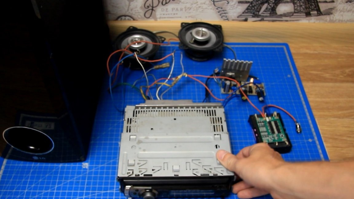
As a result of this connection, the sound has become better and more interesting. And this is one of the applications of this amplifier. Also, this amplifier can be used in conjunction with a car radio. Connection is similar to store amplifiers.To connect to the radio must have a linear output.
Here's the way the view into the thermal imager:
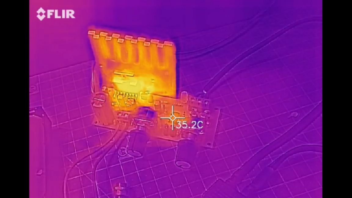
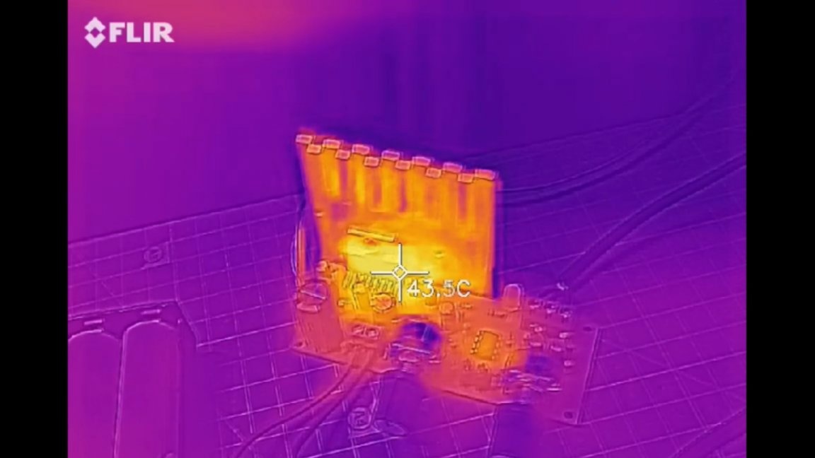
It can be seen that the opamp of the filter warms up a bit, but the main heating is the TDA7377 chip.
In the future, such an amplifier can be installed in a box or subwoofer enclosure, this is optional. That's all. Thank you for attention. See you soon!