
In this article, Roman (author of YouTube channel "Open Frime TV") will show how he do it yourself assembled a simple and reliable source of food on-duty, which anyone can repeat if desired.
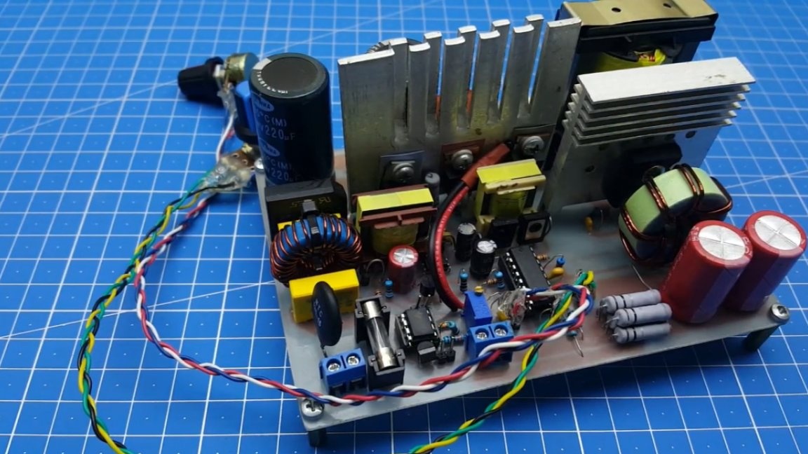
Not so long ago, the author completed one large project of a laboratory power supply unit with adjustment on the high side. It had to use a standby power supply unit, since it is impossible to do self-locking on regulated power supplies.
In the first version of the circuit, Roman used the duty room on the chip.
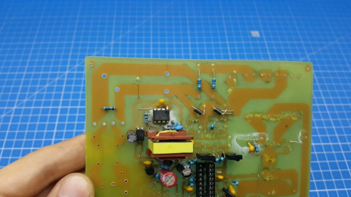
But such a solution created some problems. Firstly, not everyone has the opportunity to buy such a chip, and secondly, there is a risk to buy not an original component, in other words, run into a fake. Therefore, it was decided to find on the World Wide Web and test the standby power supply circuit in operation.
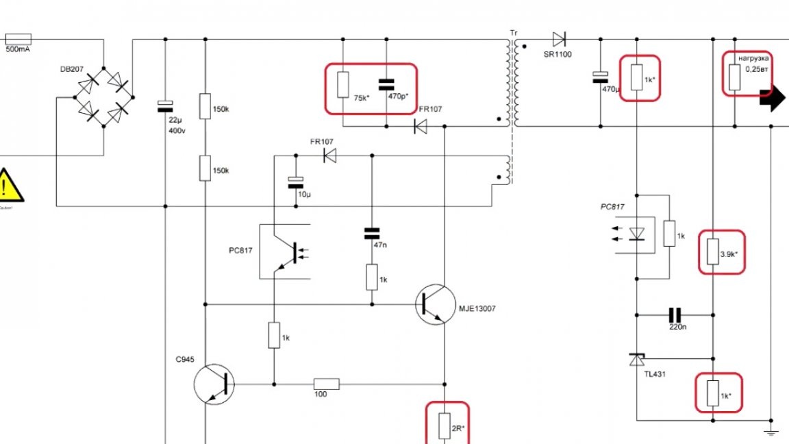
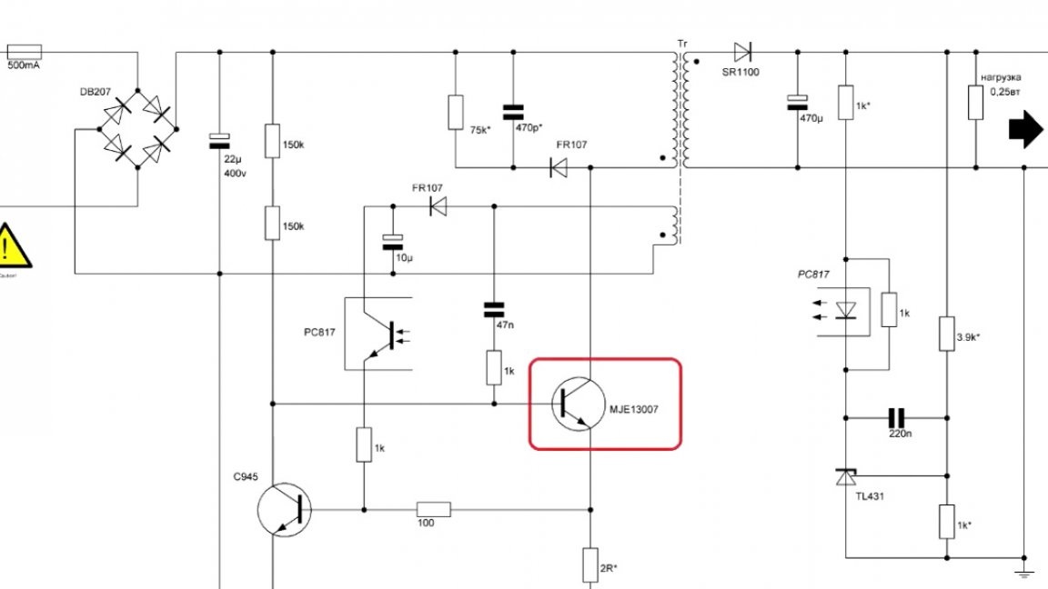
Such was found on the site "RadioKot" by Starichok (Starichok51):

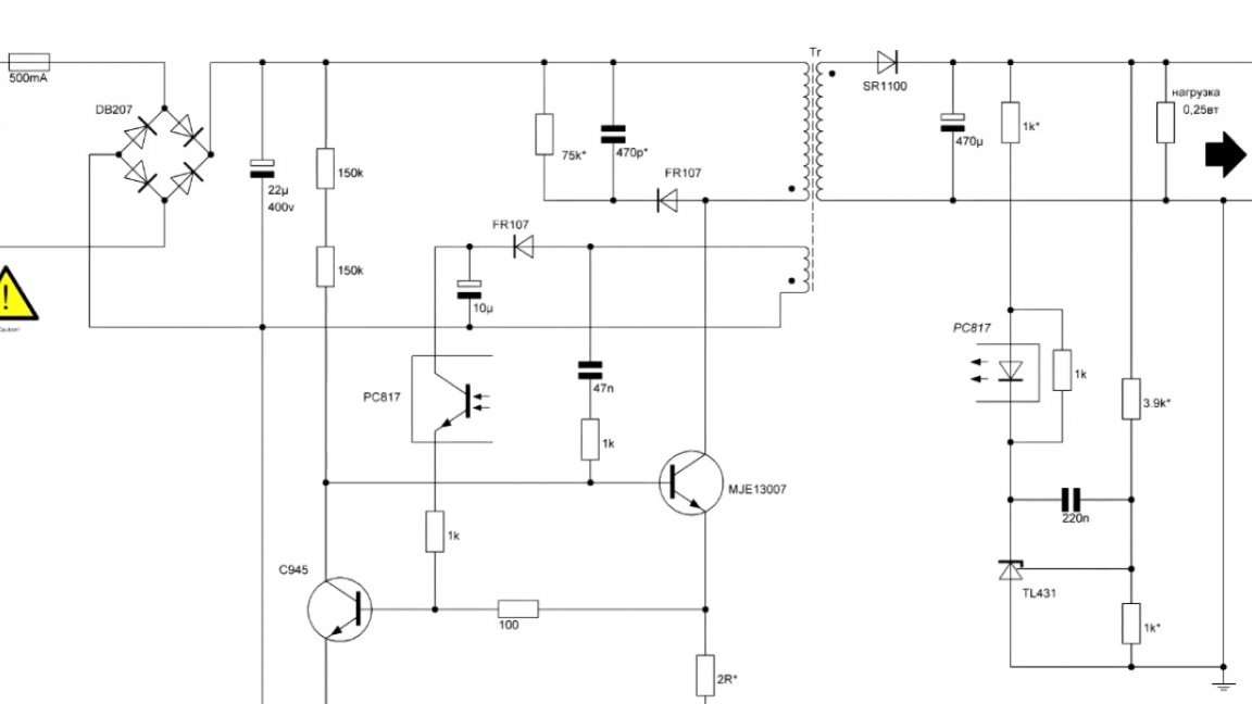
The presented circuit does not contain scarce parts and they can always be removed from the old unnecessary computer power supply, which can be found in almost every radio amateur.
For all its simplicity, this circuit has high reliability, has output voltage stabilization and is not afraid of output short circuit. In general, as they say, a complete set. The maximum current at a voltage of 12V should not be more than 500mA. But even such a current will be quite enough to power the control system, indication and cooler.
Of course, this scheme can be used for other needs. Some elements of the circuit will vary depending on the parameters of the output voltage and current. Such elements in the diagram have a special designation (with an asterisk) and are valid only for an output voltage of 12V.
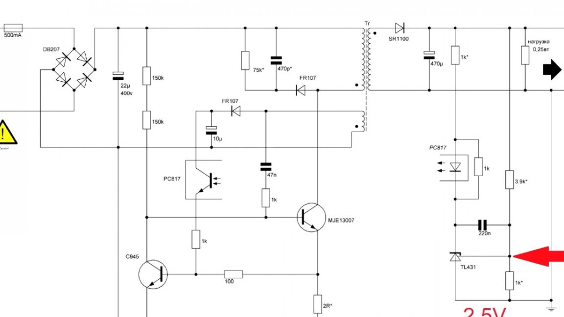
Next you will see all the necessary calculations. The simplest thing here is the calculation of the divisor by.
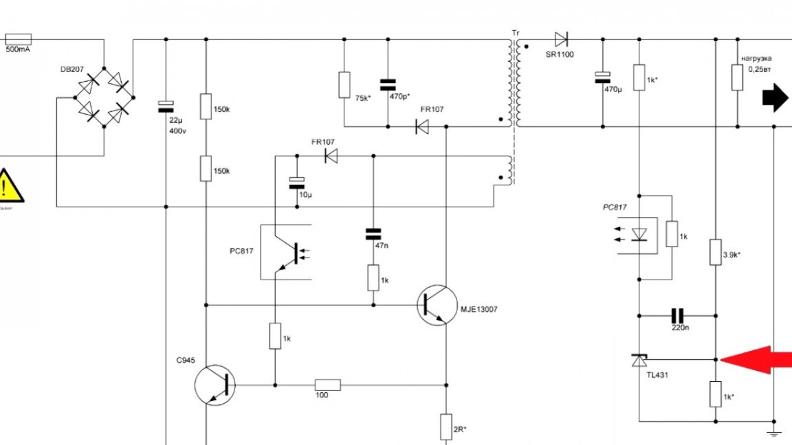
At rated output voltage, the indicated point should be exactly 2.5V.
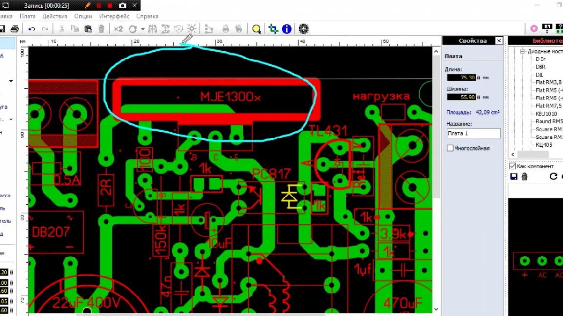
It is also worth noting some elements of the scheme. Firstly, it is a power transistor.
In this case, you can use it here.
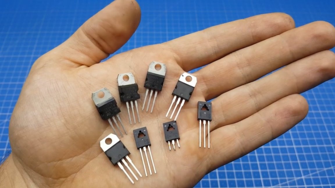
Transistors with this marking are usually used in the watch room and in the power part of computer power supplies.
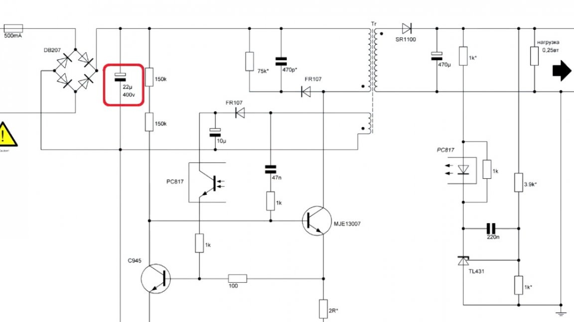
The input capacitance of the source can be from 22 microfarads to 47 microfarads with a voltage of 400V.
Next Schottky diode output.
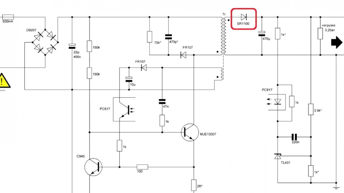
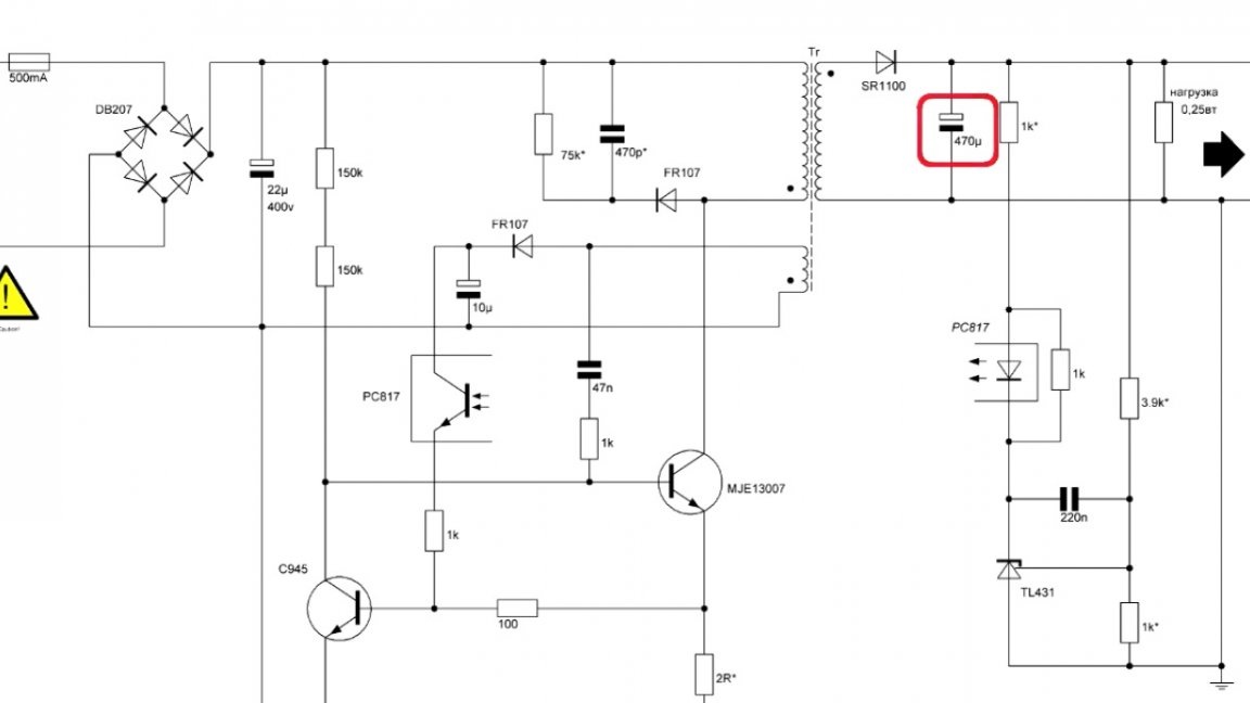
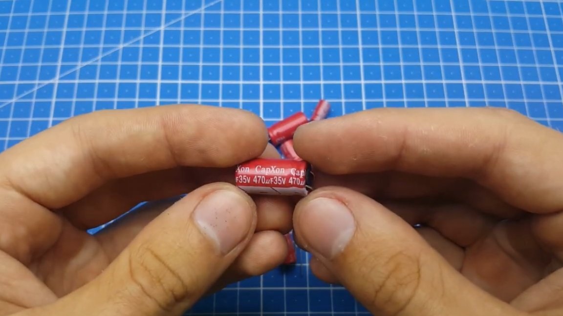
Here it is necessary to use a 1A diode and a voltage of 100V, this will be the most optimal option.You choose the output capacity for your tasks, it should be, moreover, the larger its capacity, the correspondingly less will be ripples in the output.
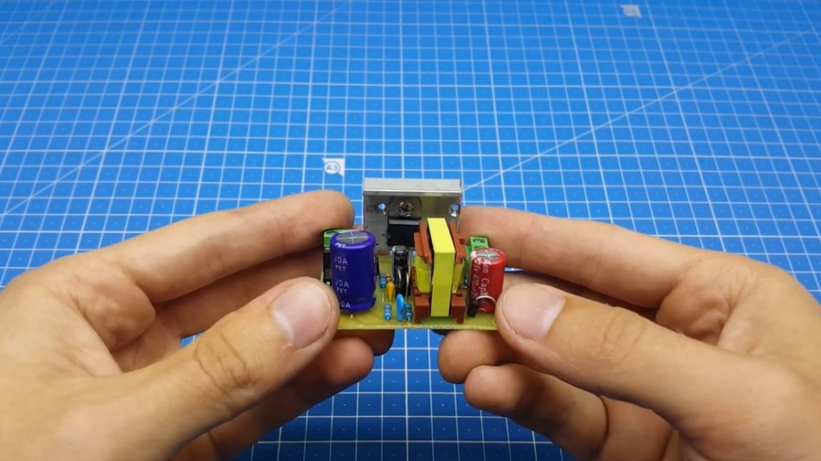
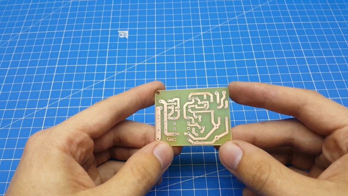
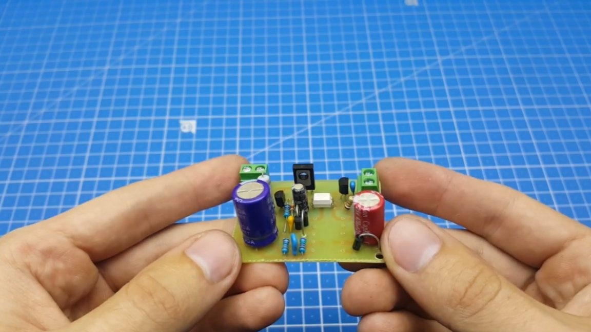
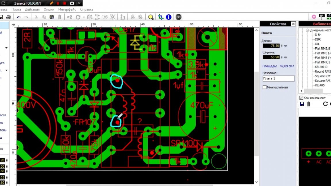
Now you can begin to manufacture the prototype. To do this, the first thing the author drew here is a printed circuit board:
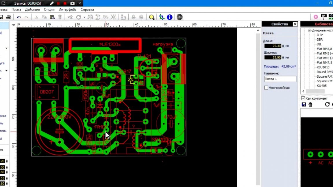
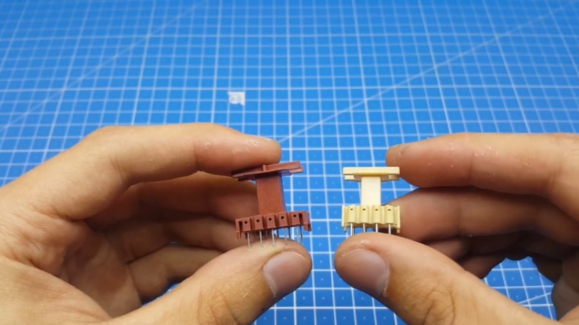
As you can see, the board is quite compact in size. The transformer size was used E20, since only such were at hand.
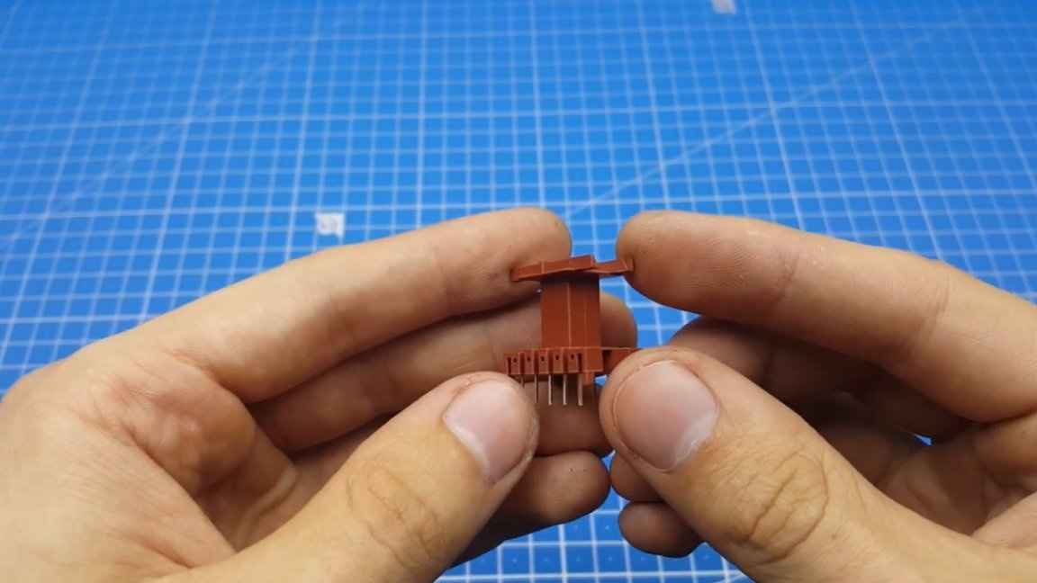
Of course, E16 can also be used for this project, then the board will be even more compact.
The author left a place for the radiator here, such an arbitrary one, since each one will have his own.
Since this is our prototype, it is possible to manufacture a board using the LUT method, and in the future it will be possible to order boards at a Chinese factory.
So, the board is made, now you can begin to solder it.
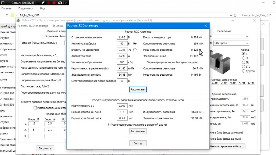
There is practically no difficulty in this, they come further when it will be necessary to calculate and manufacture a transformer. But before its manufacture, it is necessary to determine the voltage at the output. Next, using the program of the same Old Man widely known to radio amateurs, we will make the necessary calculations.
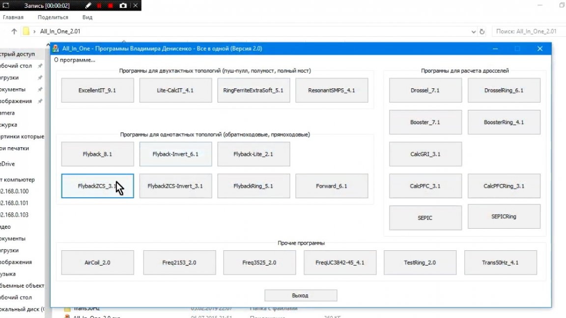
Enter the data in the appropriate fields.
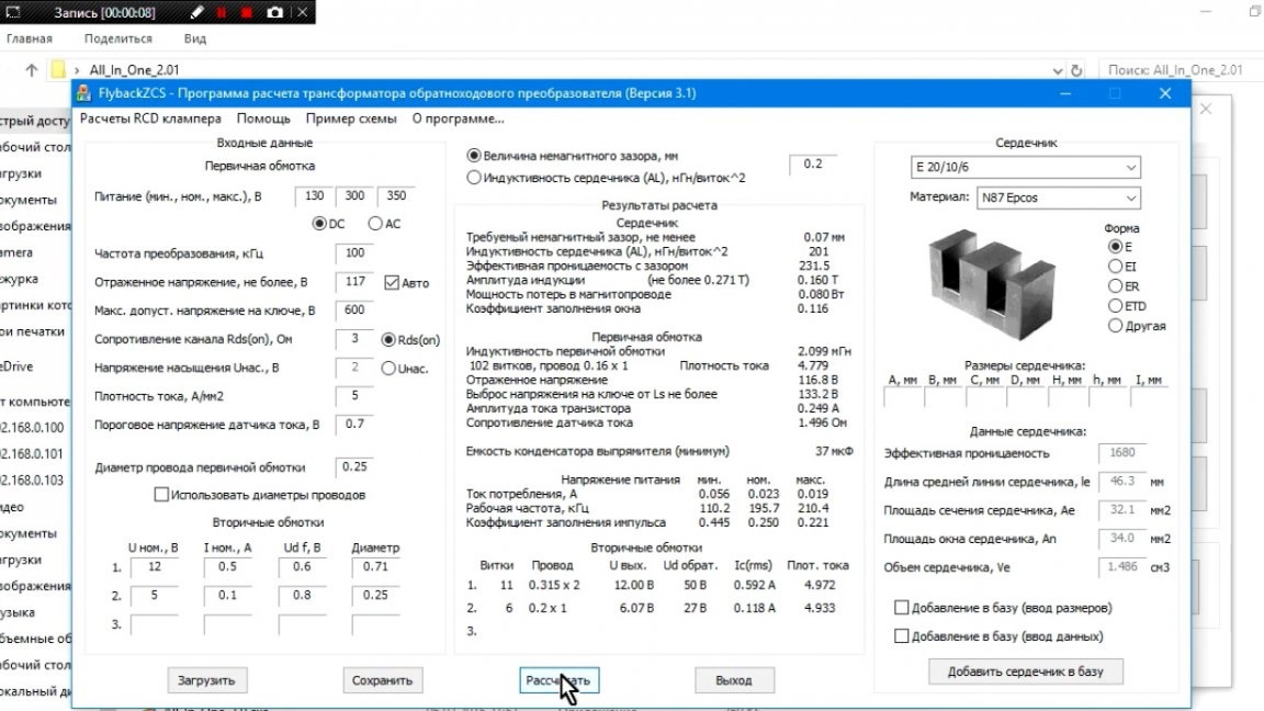
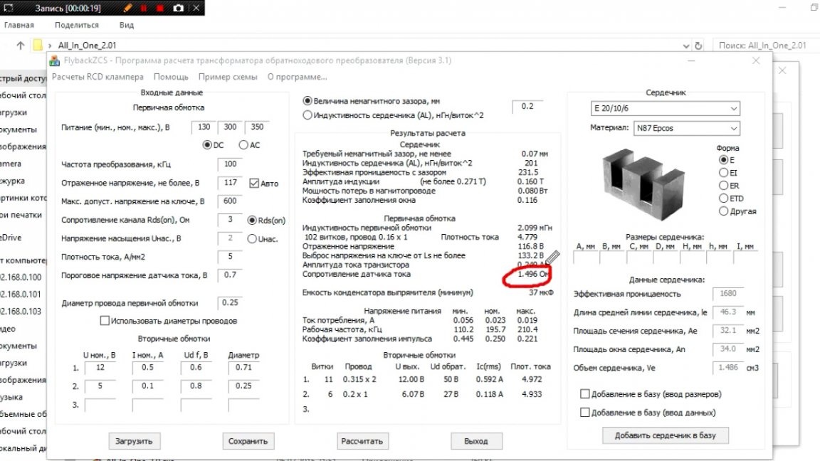
Since this is a flyback topology, the transformer must have a gap. In addition, this computer program will calculate the resistance of the current sensor resistor and snubber.
Now all we have to do is simply buy all the necessary details according to the results issued by the program, and, accordingly, solder them to the board. I don’t know what we would do without a respected Old Man.
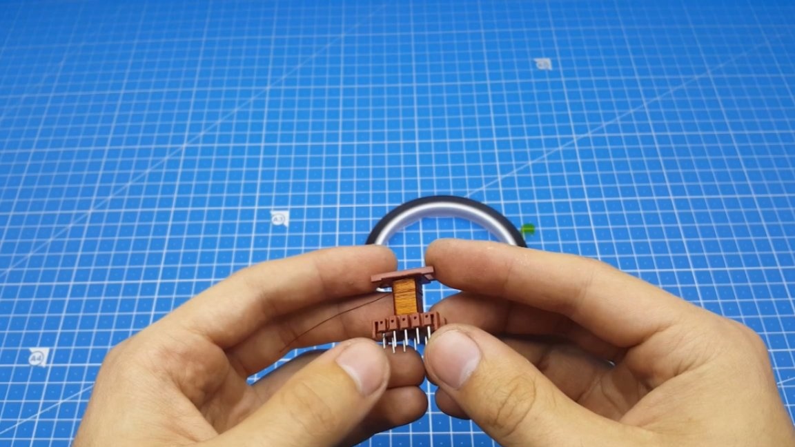
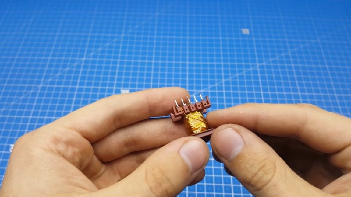
Next, you can begin to manufacture a transformer. This time, let's try to do everything as correctly as possible, dividing the primary into two parts to reduce the leakage inductance.
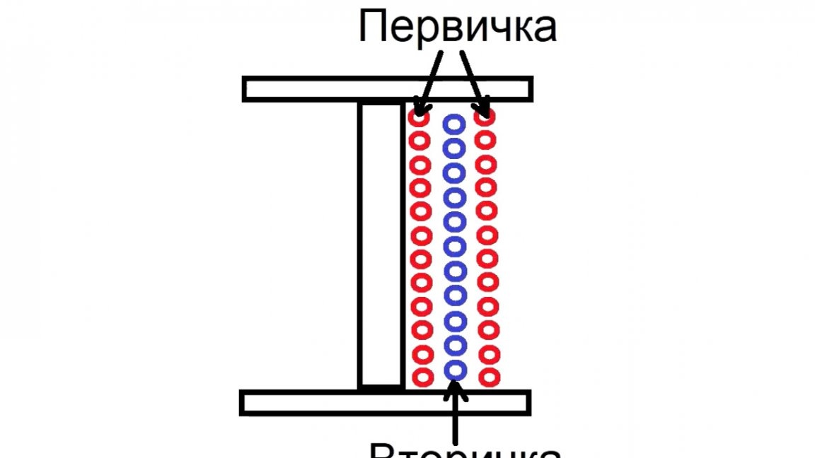
We wind all the windings in one direction, the beginning and end are shown on the printed circuit board.
The first step is to wind half of the primary.
Next, isolate it with a thermal tape. This action must be repeated for each winding.
The next step we wind the secondary. In this case, it is highly desirable that it fit in one layer.
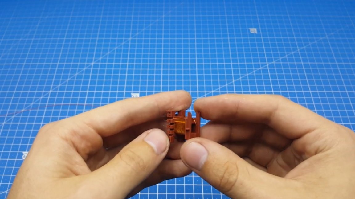
Then there is another layer of insulation and you can start winding the second half of the primary. It is necessary to wind the coil as neatly as possible, if this is not done, then instead of a transformer we will get a warming brick.
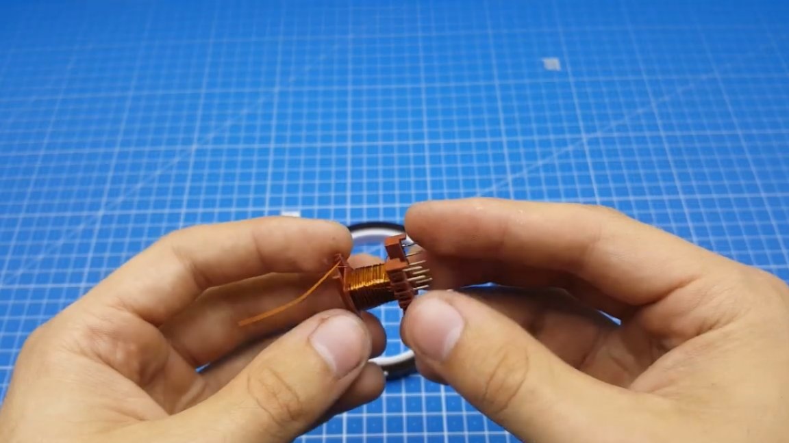
The last step is to win self-winding, since it is not so important.
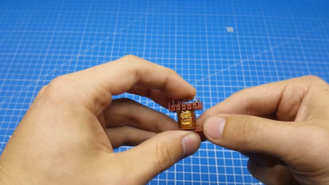
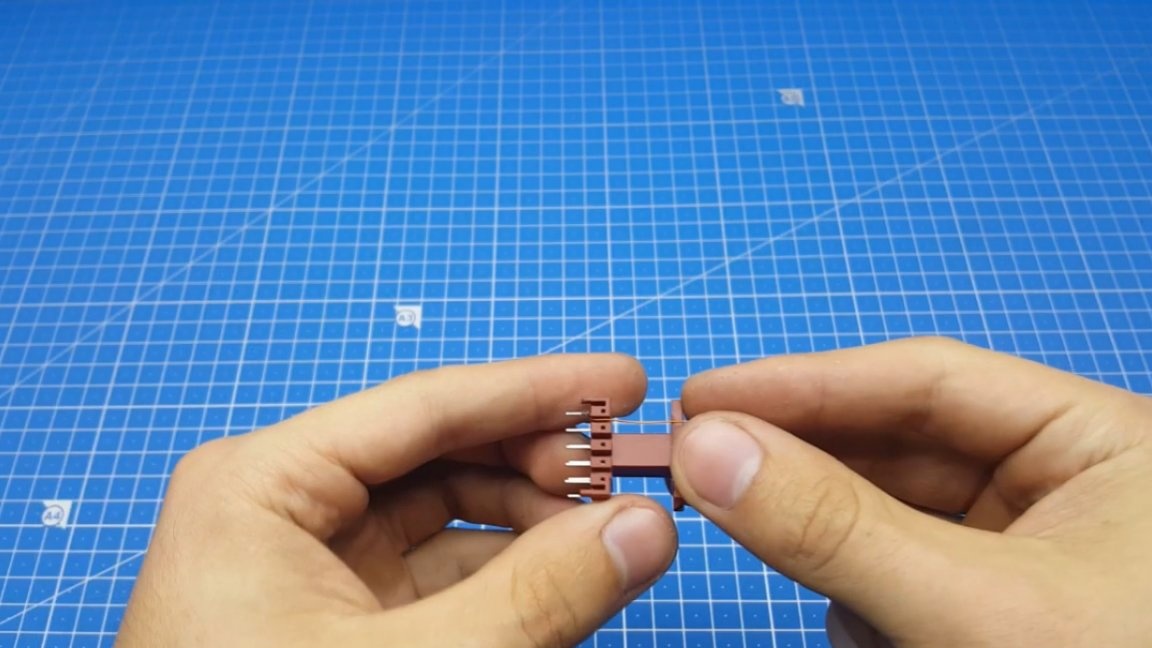
As mentioned above, this transformer needs clearance. You can either buy a core with a ready gap, or make a gap yourself with your own hands. The gap itself, as we know, is necessary to reduce the inductance of the winding. If there is no gap, then the core will go into saturation.
The gap can be made literally from everything at hand. The author used A4 paper sheet for this.
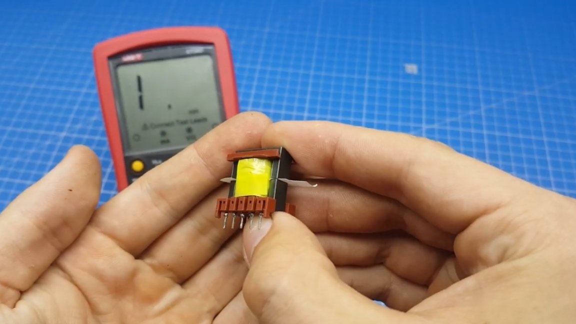
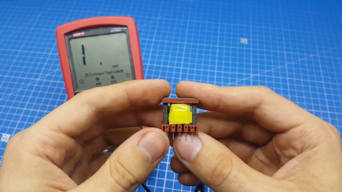
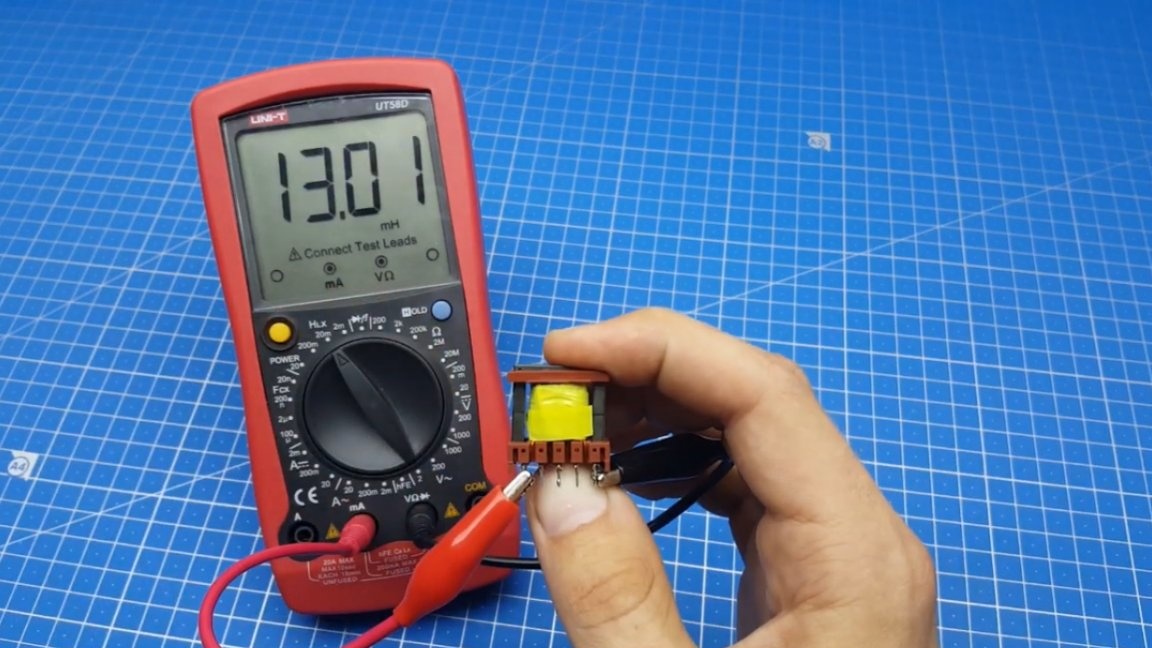
And now you can visually see how the inductance has changed, compared to a core without a gap.
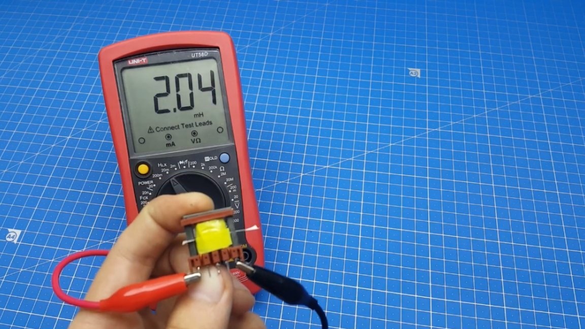
In conclusion, it is necessary to compare the obtained inductance value with the calculated Starichka program.
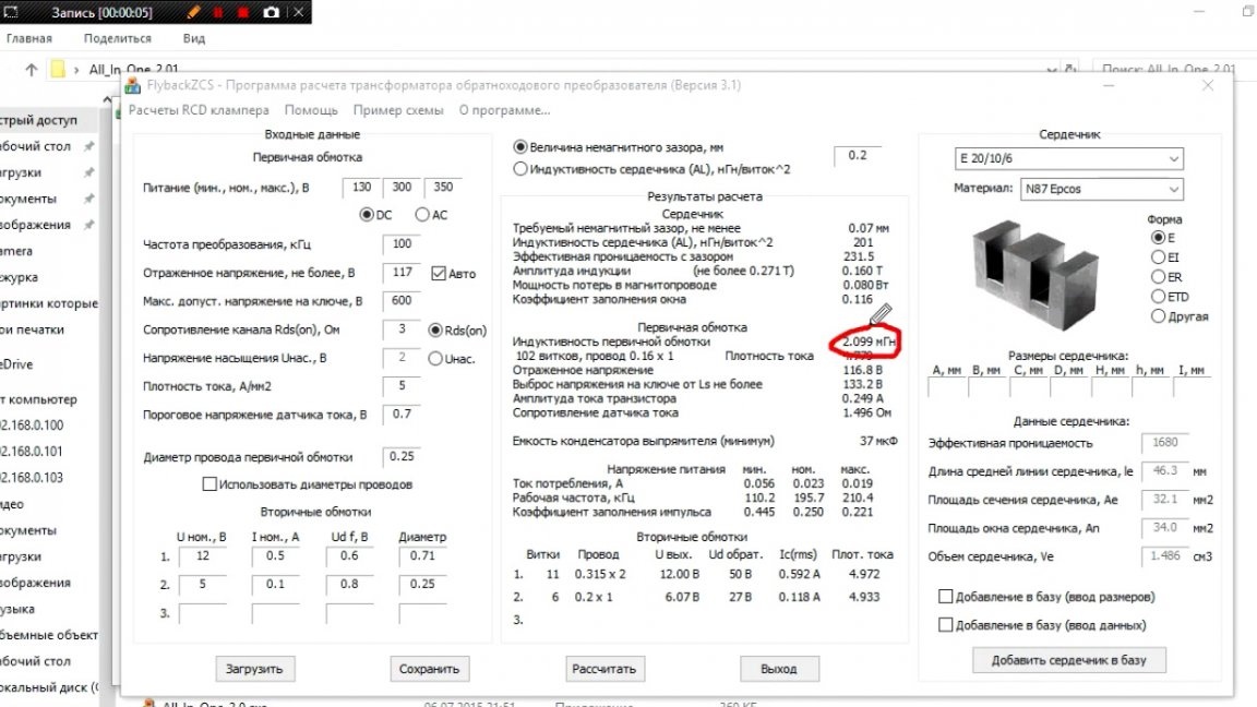
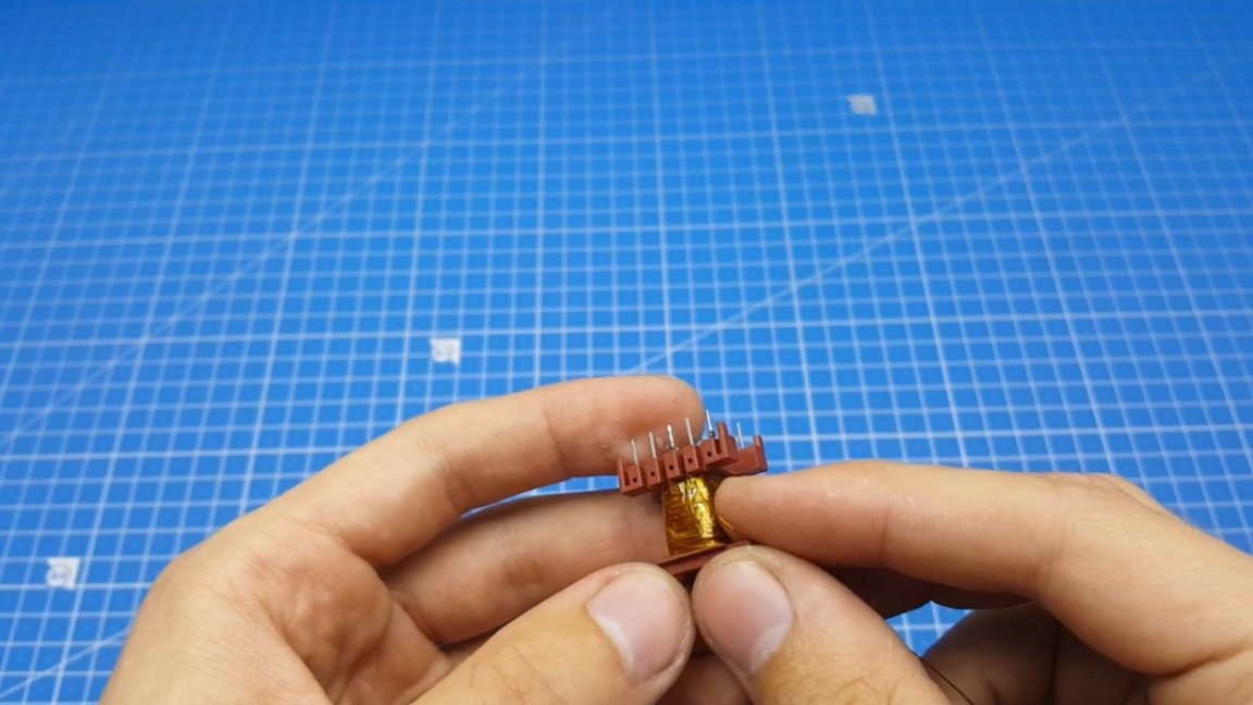
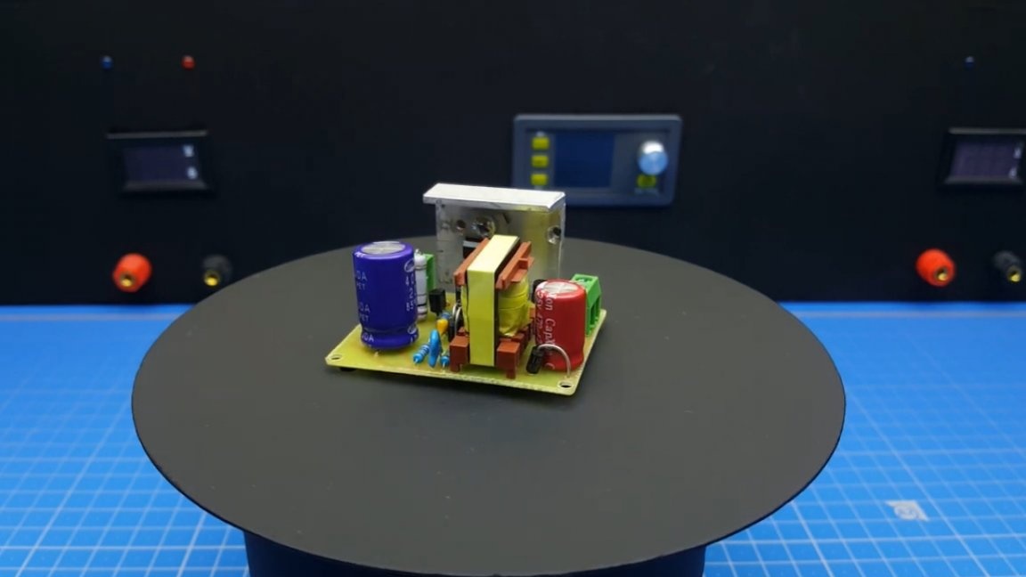
As you can see, the values practically coincide. The transformer is completely ready, you can install it on the board.
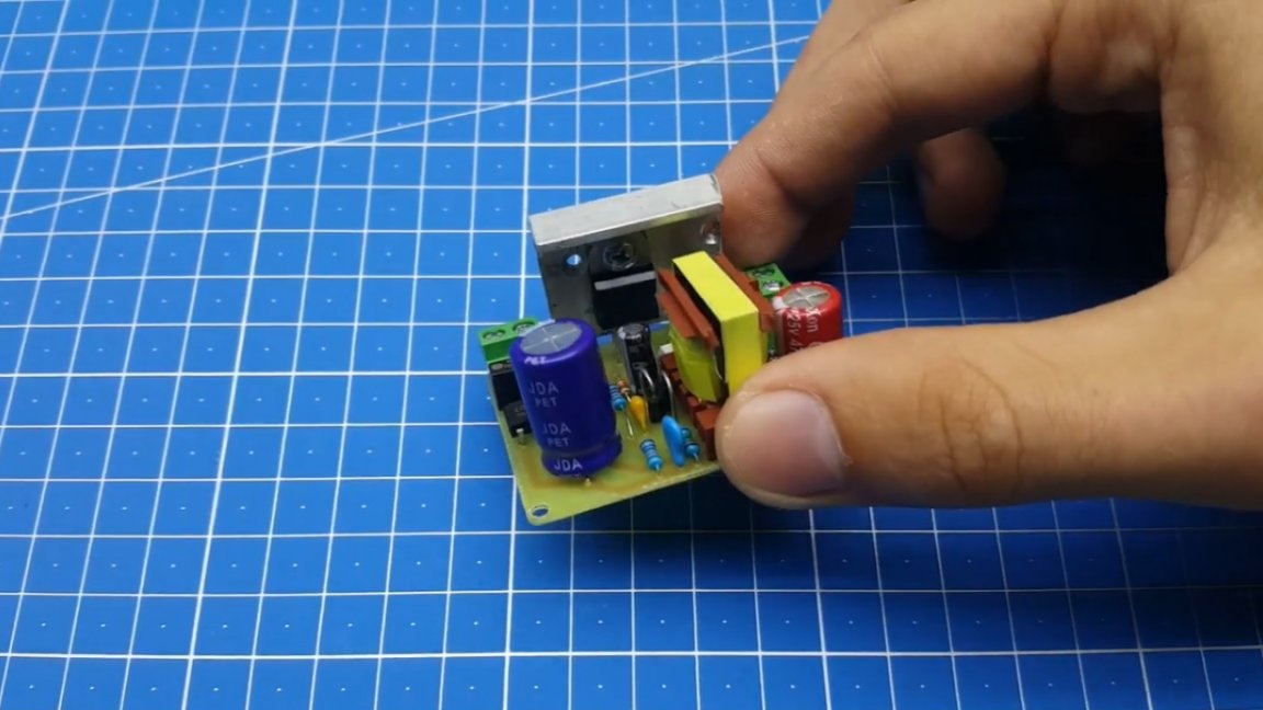
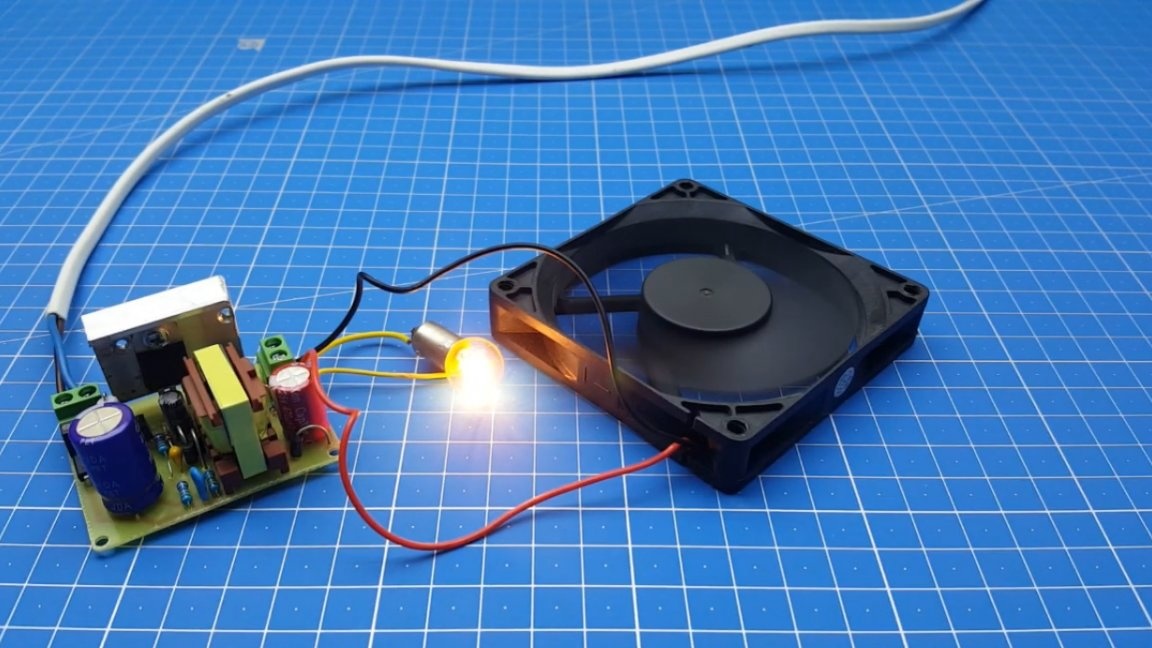
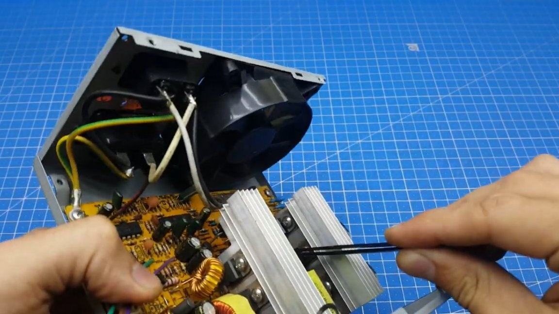
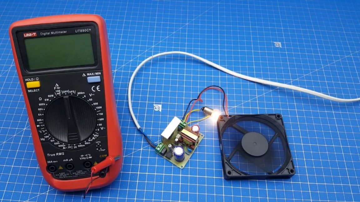
That's all, our duty room is ready. Now let's check our homemade power supply in operation. To do this, we turn on the power supply in a network with a voltage of 220V, while the first connection is preferably made through a miniature incandescent lamp.
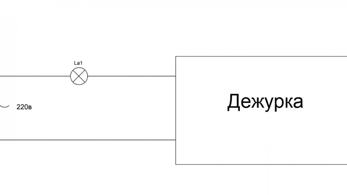
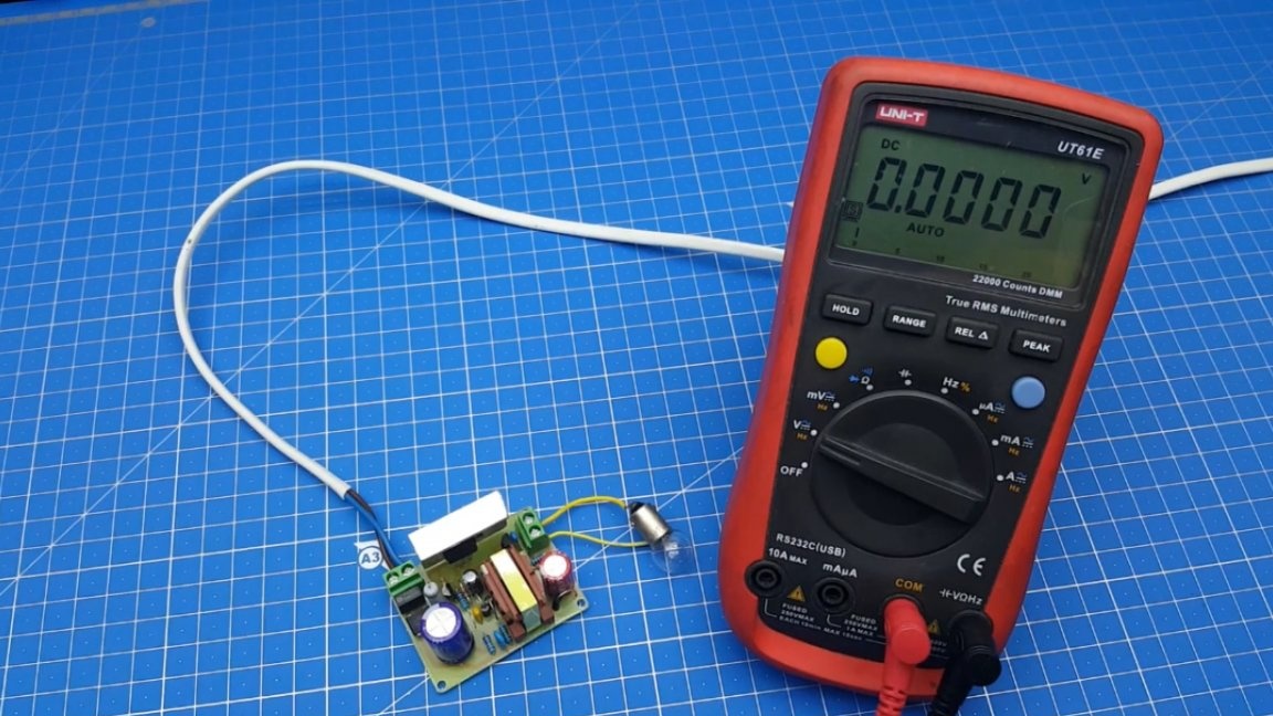
If all is well and nothing explodes, we check the output voltage, in this case it should be 12V.
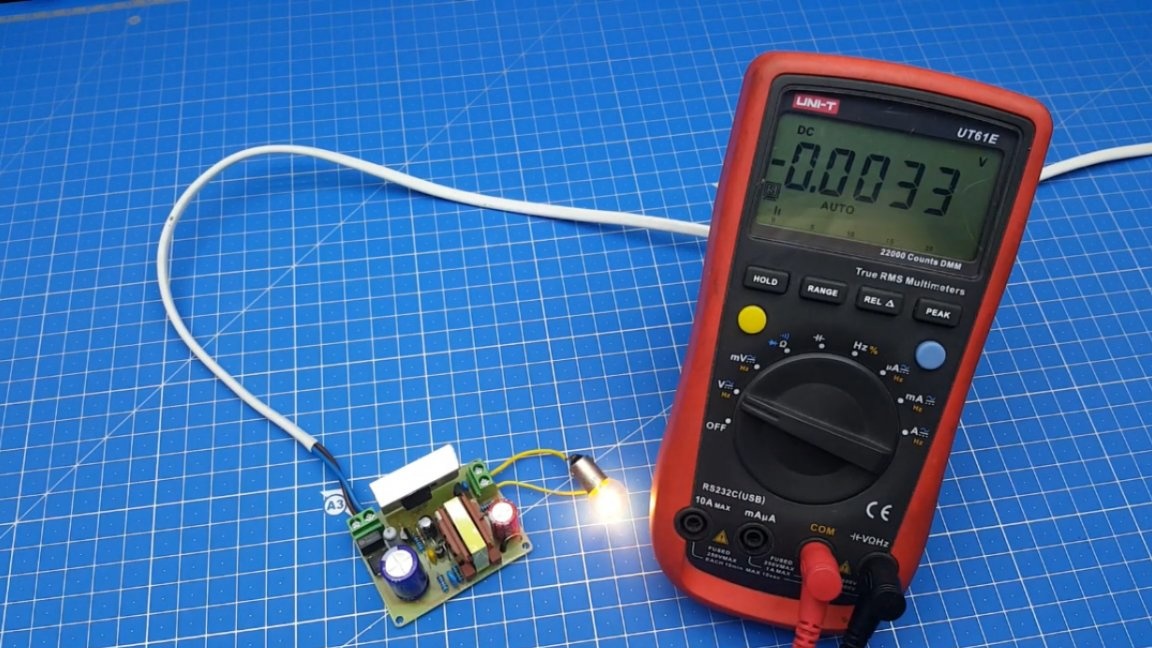
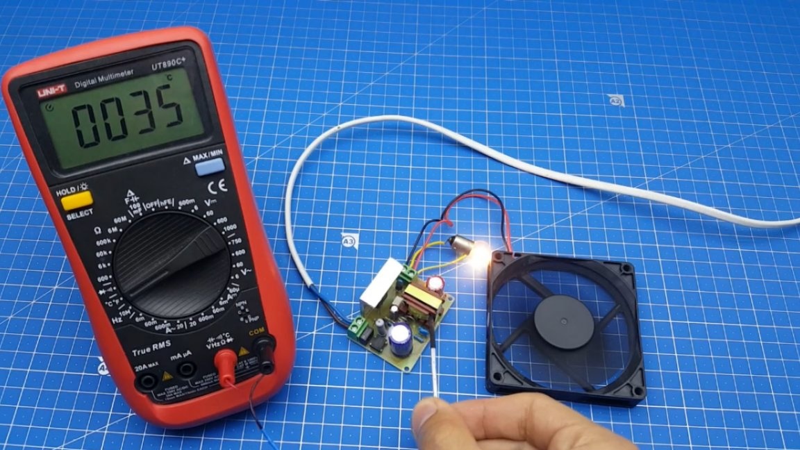
Great, now you can remove the light bulb and turn on the homemade network directly. As a load, the author connected two elements: a cooler and an incandescent lamp.
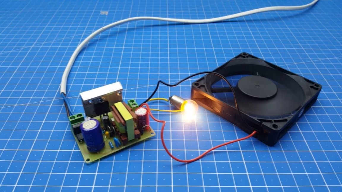
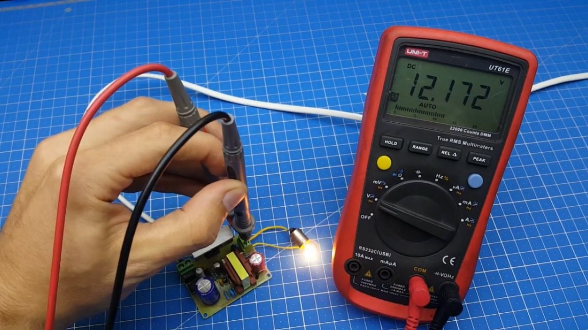
Let's look at stabilization without load and with load.
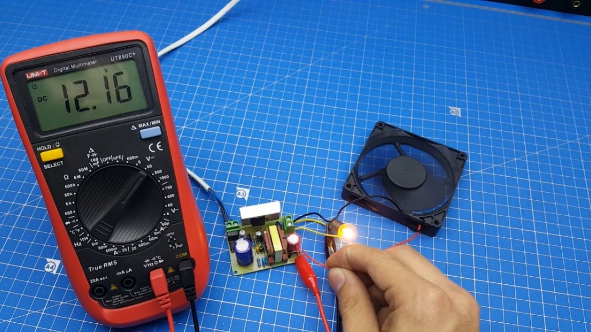
As you can see the readings of the multimeter have not changed, which means feedback is responding adequately.Further, the author decided to leave the power supply turned on for a while in order to check the heating.
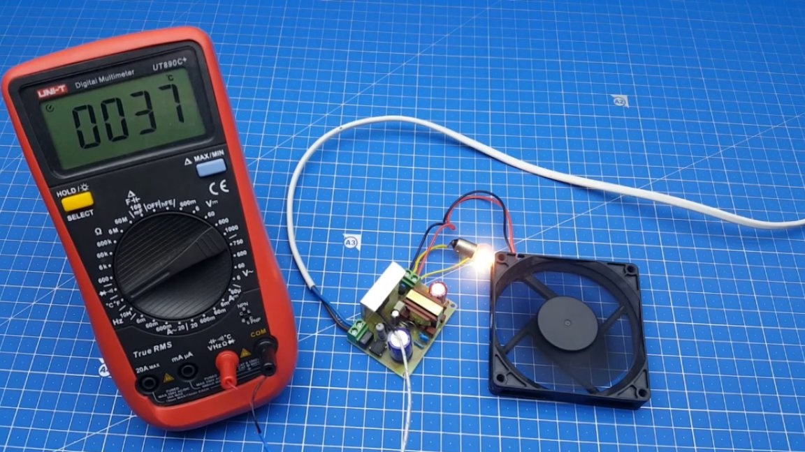
In the image above you can see the temperature measurements after an hour of operation of the device. In principle, this is not a bad indicator, especially since in the real block the author will have a cooler for blowing. As a result, we got a pretty good standby power source.
That's all. Thank you for attention. See you soon!
Author's video: