» Electronics »Timer for photo printing

Timer for photo printing


Since the author of Instructables under the nickname ElectroGuruji liked the fact that I translated his article, I decided to translate another one. Old-timers will remember how the time relay for photo printing was once popular. Any self-respecting periodical for masters has published at least three schemes of such homemade in year. Today, film photography is being revived, which means that the sky comes again in these assistant devices, which allow to obtain better photo prints with less labor.

The time relay is made on a 555 timer chip (KR1006VI1), a feature of which is the immutability of the shutter speed when the supply voltage changes within acceptable limits. But since the relay switching the enlarger is taken with a 12-volt winding, the supply voltage of the device should be chosen close to this value. Too little - the relay will operate uncertainly, too much - will overheat or even burn out. Automotive relays are unsuitable - they do not provide sufficient insulation.

Chip 555 can operate in the modes of the Schmitt trigger, multivibrator and single vibrator. The mode is determined by the switching circuit, in the proposed time relay, the microcircuit is included as a single vibrator. At the moment of starting the single-shot, the time-order capacitor is discharged to a voltage below 1/3 of the supply voltage, and the shutter speed begins. The capacitor is slowly charging at a speed determined by the resistance of the timing resistor. As soon as the voltage across the capacitor reaches 2/3 of the supply voltage, the shutter speed stops. The device diagram is shown below:


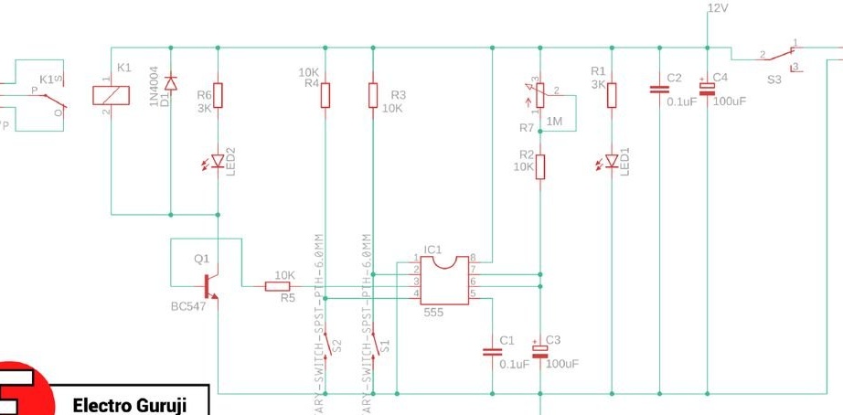
While the shutter speed lasts, a logical unit is present at the output of the timer. If the load is turned on between the plus and the output, it turns off, and at the end of the exposure it turns on again. If between the output and the common wire - on the contrary, which is required in the time relay for photo printing. The current consumed by the load can reach 200 mA. Although this is enough to control the relay directly, the master decided to add an intermediate key on the transistor. It also includes a resistor to limit the base current and a protective diode connected in parallel with the relay coil in the opposite direction.

The button connecting the common wire to pin 2 of the microcircuit serves to start the shutter speed, and connecting the common wire to pin 4 - for its early termination. When the buttons are depressed, the resistors pull the corresponding pins up.

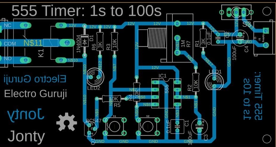
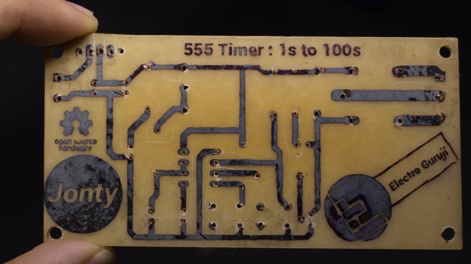
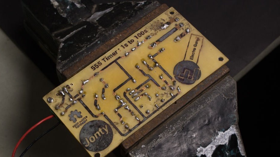
The author makes a printed circuit board LUT. Files: source code (diagram, board) under GPL v3, direct link on pdf for print. This is how the board looks in theory and in practice:


Video about the manufacture of the board:


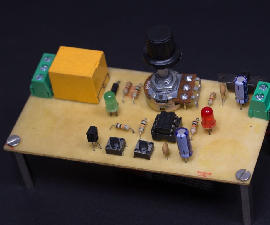
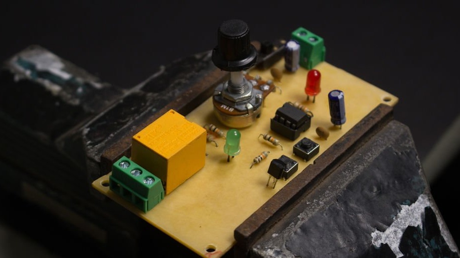
When assembling, the master again, as in the previous article, uses a vise as a "third hand". Of course, doing so is recommended only if you can accurately calculate the clamping force. Assembled board on both sides:


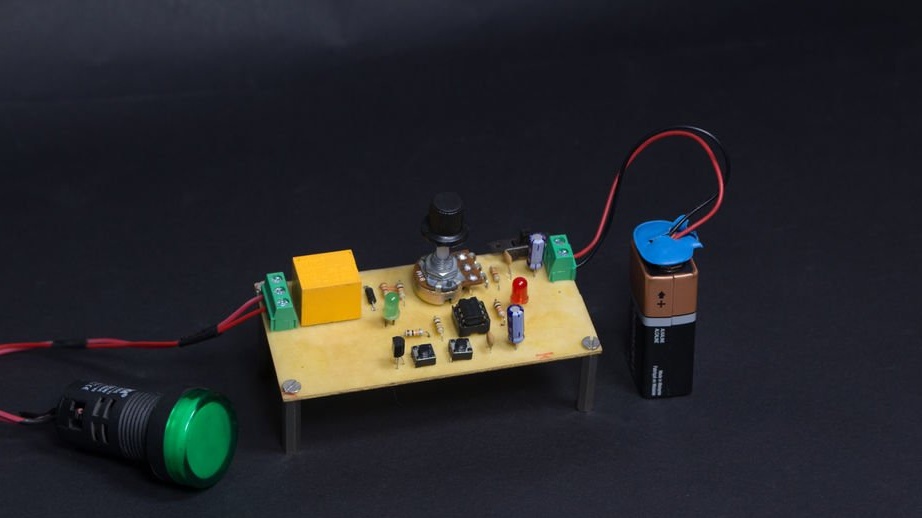
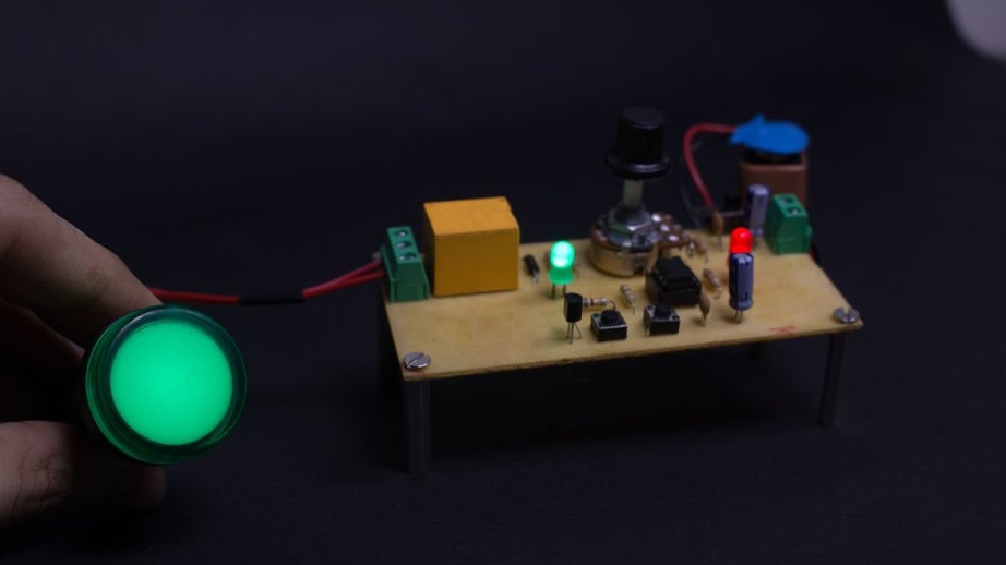
When checking, the master uses a standard LED indicator lamp similar to the AD22DS as a load. The numbers 22 indicate the diameter of the bore hole - 22.5 mm There are also AD16DS lamps for holes of the corresponding diameter.


The wizard sets the shutter speed:


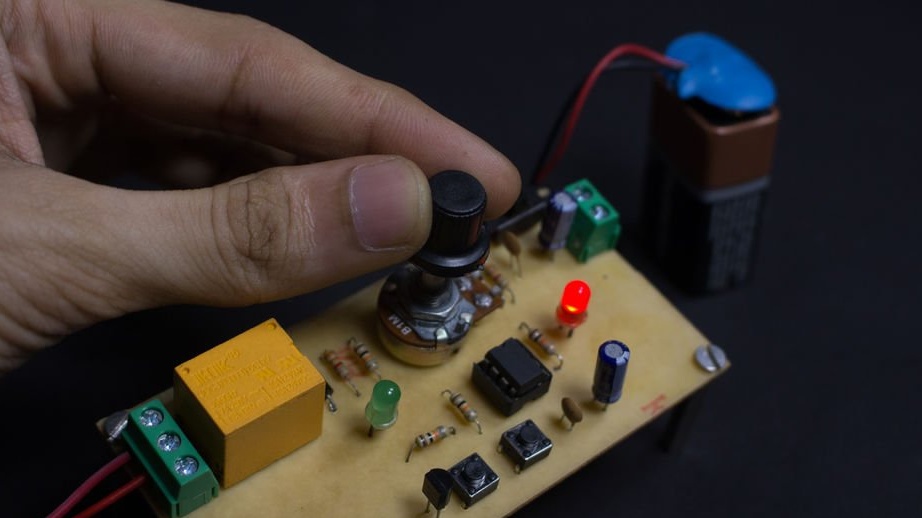
Starts the time relay:
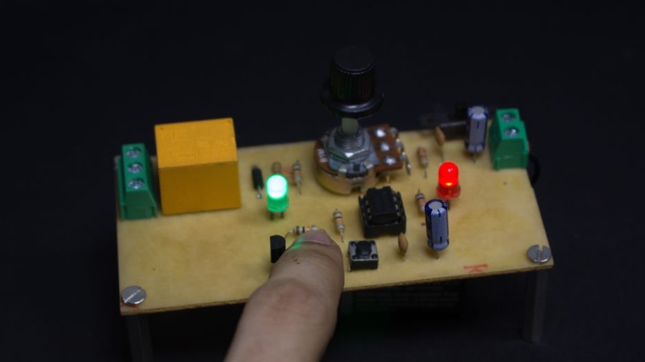


The lamp is on:


Video about using the time relay, the action of the start and early reset buttons is shown:


The master does not show the addition of a fuse or circuit breaker to protect the power supply and the enlarger lamp, the manufacture of the housing and scale for the variable resistor, as well as its calibration. But for all this you need to spend time necessarily. And on the table of the photographer-filmmaker will be comfortable electronic assistant device.
4.3
6
5.3

Add a comment

    • smilesmilesxaxaokdontknowyahoonea
      bossscratchfoolyesyes-yesaggressivesecret
      sorrydancedance2dance3pardonhelpdrinks
      stopfriendsgoodgoodgoodwhistleswoontongue
      smokeclappingcraydeclarederisivedon-t_mentiondownload
      heatirefullaugh1mdameetingmoskingnegative
      not_ipopcornpunishreadscarescaressearch
      tauntthank_youthisto_clueumnikacuteagree
      badbeeeblack_eyeblum3blushboastboredom
      censoredpleasantrysecret2threatenvictoryyusun_bespectacled
      shokrespektlolprevedwelcomekrutoyya_za
      ya_dobryihelperne_huliganne_othodifludbanclose
14 comments
Guest Alex
And where did you get that film photography is reborn? Now do not find any film or photo paper?
Guest Vita
By appointment I suggest. idea: I’ve been dreaming for a long time and there was even an attempt to make a relay that would work automatically when the gas stove was turned on, with a time adjustment of the signal and the button, if you want to continue. The primary signal from the gas electric igniter.
That's okay. However, it will be necessary to significantly redesign the design.
Author
It is, however, very suitable for printing film photos the classic way with enlarger. It produces stable intervals not depending on Vcc.
The person who translated Your article think up with the wrong title.
What is it about that this is just a classic time switch, not tied to photo printing.
Electro guruji
As I have mentioned in other comments, I made this timer to be used as a Motion triggered timer switch and NOT for photography.

The project simply demonstrates a simple application of the 555 timer in the Monostable mode.

It seems like the main purpose of the project got lost in translation.
Electro guruji
The purpose of the timer was to act as motion triggered timer. I didn't make it with the intention of using it in photography.

I think the main purpose of the project got lost in translation.
Electro guruji
I made this timer not for photography but instead to be used as a motion activated timer.

For example, one can connect a PIR sensor to the trigger input of the 555. If a person passes the sensor, the relay is activated for a certain amount of time (determined by the position of the switch). A night light could be connected to the relay.

The project demonstrates a simple application of the 555 in it's Monostable mode.

I think this article has got a few translation errors. Hopefully you can correct them.
And also replace the green LED with red. Although there is a slight flare from him, but why do it badly, if you can do better. And break the variable resistor into coarse and accurate.
Also, if we are not talking about an abstract timer, but specifically for photo printing. Ergonomics are not given any attention at all, and for working in the dark, almost to the touch, this is very important.
Maybe I misunderstand something, but if this relay is for photo printing, then the relay contacts should withstand the magnifier lamp and the red light as a load. Accordingly, there should be two standard outlets operating in antiphase (when the magnifier lamp is turned on, the red light goes out, and vice versa). It is also necessary to calibrate the exposure time scale. With color photo printing, it is desirable to have something like a sound metronome. scratch
The appointment may be different. And what is the bad performance, what are not SMD components? So if the author has a stock of old components, then what - throw it away? For the time relay, special compactness is not required, and 555 is an “evergreen” beautiful IP, old, but not canceled by anyone.))
As for the renaissance of film photography, it is very limited. PMSM, this is either a temporary mode for the rich "Pinocchio", which will soon pass, or the reluctance of the old "prisoners" to switch to the "digital".
Guest knnk007
It seems to me alone that this is out of date as if by appointment. and on performance for 20 and 10 years?

We advise you to read:

Hand it for the smartphone ...