» Electronics » Sound and Acoustics »Amplifier transistor 13002

Transistor Amplifier 13002


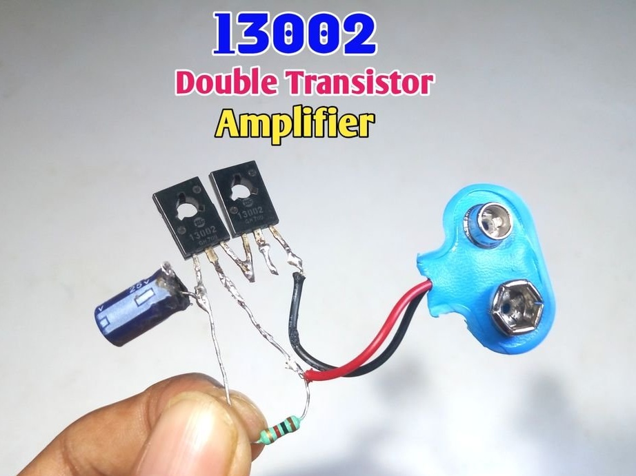
Although compact fluorescent lamps are already unpopular, many craftsmen have accumulated boards from them. Among other components, there are transistors of types 13001, 13002, 13003. Although they are considered key, it is not difficult to transfer them to linear mode in the generally accepted way, while the output power is, of course, small. So, for example, the author of Instructables under the nickname Utsource123 assembled a composite of two such transistors (it is also called the Darlington transistor, which made the corresponding invention in 1953) and built on it a simple single-ended audio-frequency power amplifier (UMZCH).

Since the master decided not to make an amplifier circuit, the translator had to restore it from the description and photos. The result was the most ordinary UMZCH circuit on a composite transistor without any features. On old MP transistors, it would look exactly the same. Given the opposite structure, of course.


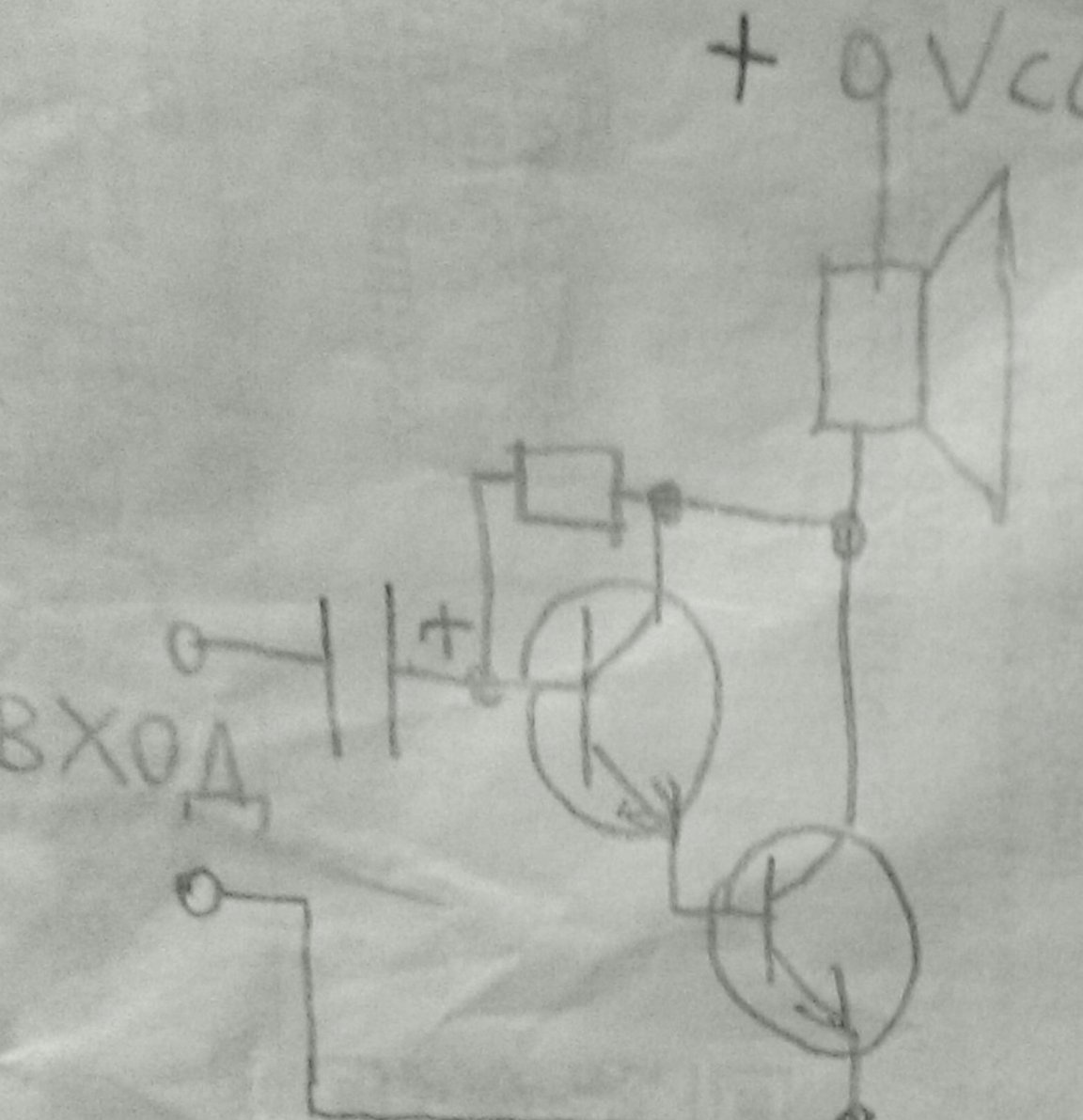
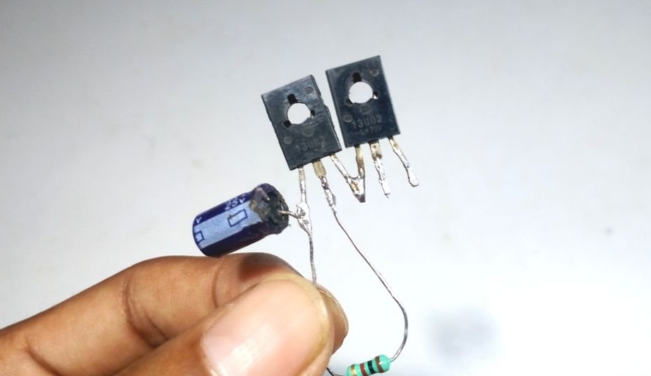
The bias to the base by the resistor, the capacitor, so that this bias does not get into the signal source - everything is as usual. 100 uF capacitor, 25 V, 1 kOhm resistor.

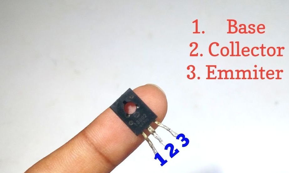
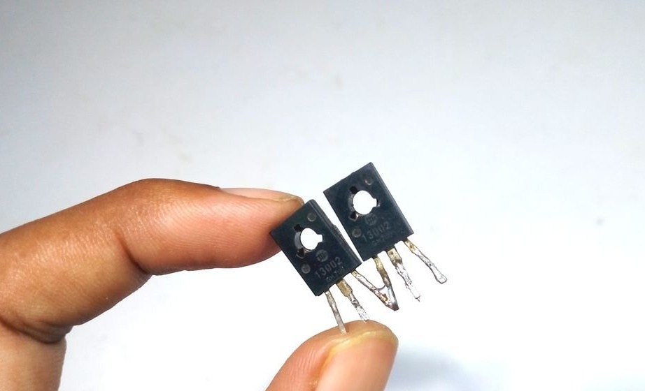
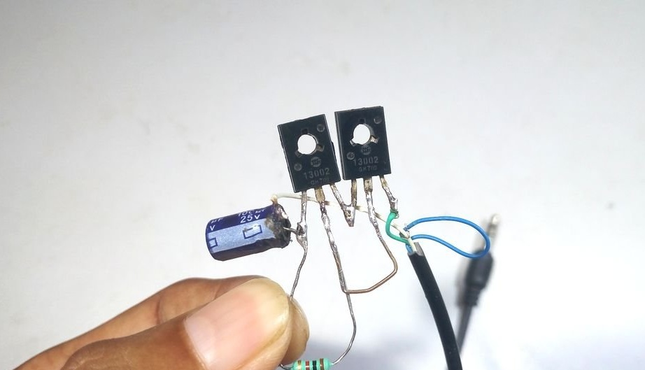
First of all, the master acquaints readers with the pinout of transistor 13002:


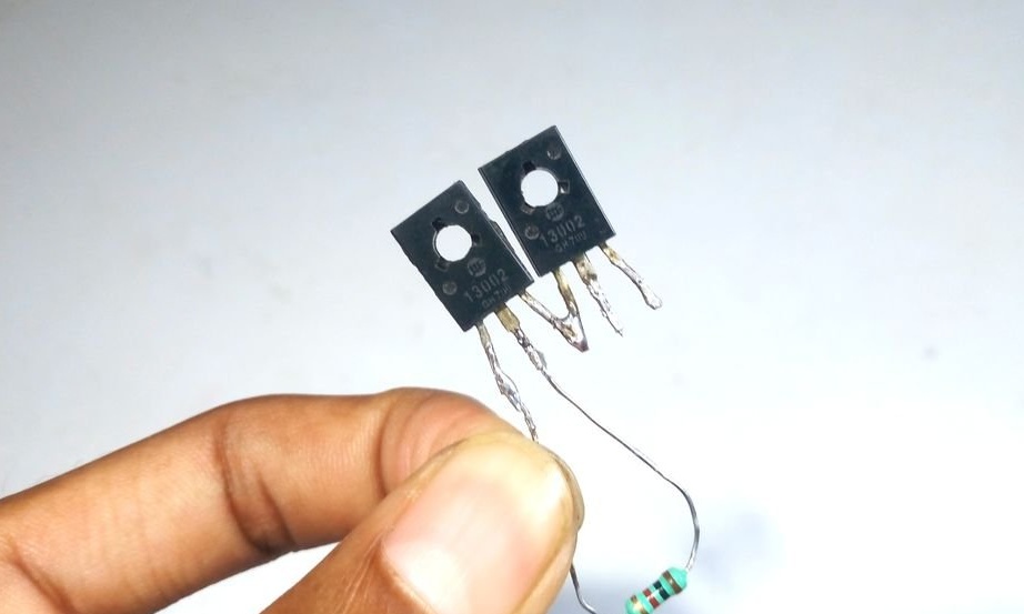
Then, as it should be when assembling two transistors of one composite, it connects the emitter of the first transistor with the base of the second. Well, they are just located nearby.


Solder the bias resistor between the collector and the base of the first transistor. Thanks to him, both transistors will work in linear mode.


Connects to the base of the first transistor the positive output of the capacitor:


Connects the collectors of both transistors with a jumper:


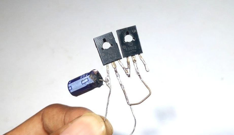
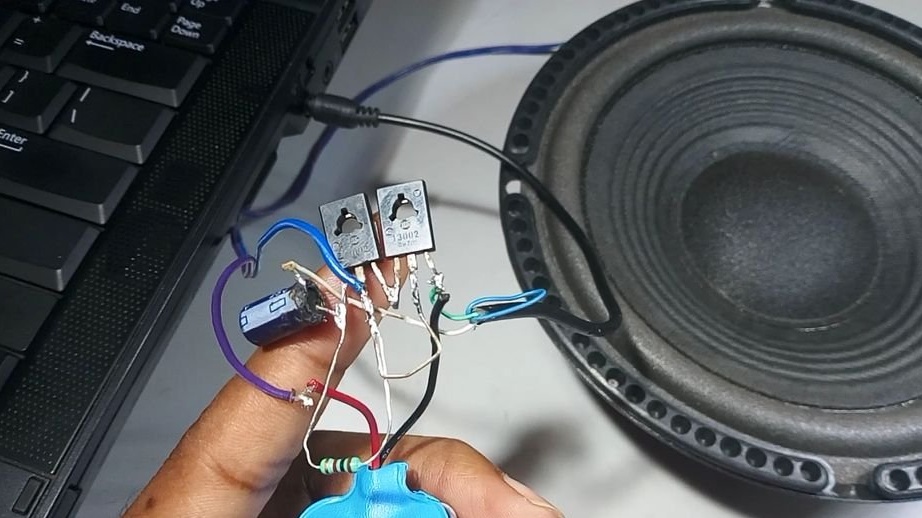
Connects a signal cable: the common wire is soldered to the emitter of the second transistor, and the output of any of the stereo channels to the negative terminal of the capacitor:


One terminal of the dynamic head connects to the power plus, the second - with the collectors of both transistors connected together. Less power is supplied to the emitter of the second transistor.


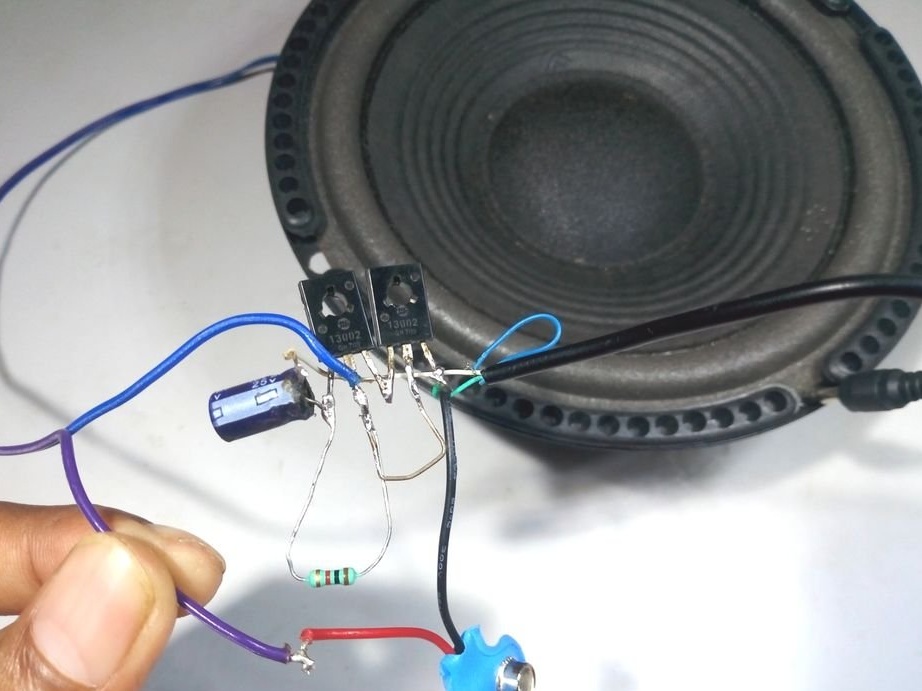
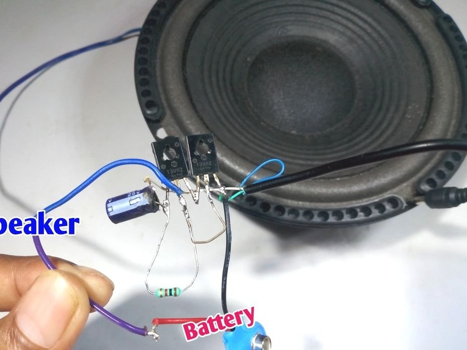
The amplifier is ready to go. If you do not add a volume control to it, you will have to take a signal source in which there is a corresponding control.And you can listen.


Gathering a second amplifier of the same type and applying a signal from another stereo channel to it will give you a stereo effect.
4.1
4.7
3.9

Add a comment

    • smilesmilesxaxaokdontknowyahoonea
      bossscratchfoolyesyes-yesaggressivesecret
      sorrydancedance2dance3pardonhelpdrinks
      stopfriendsgoodgoodgoodwhistleswoontongue
      smokeclappingcraydeclarederisivedon-t_mentiondownload
      heatirefullaugh1mdameetingmoskingnegative
      not_ipopcornpunishreadscarescaressearch
      tauntthank_youthisto_clueumnikacuteagree
      badbeeeblack_eyeblum3blushboastboredom
      censoredpleasantrysecret2threatenvictoryyusun_bespectacled
      shokrespektlolprevedwelcomekrutoyya_za
      ya_dobryihelperne_huliganne_othodifludbanclose
24 commentary
Quote: Ivan_Pokhmelev
It is impossible to imagine a demonstration model of the Darlington transistor operation as a homemade product, besides - an incorrect model. ((If we were to demonstrate the principle, we had to tell how the operating point is selected and set.
As already mentioned above, it has no practical application, it is not recommended for repetition.

Wailing and spitting is easy ..
It is much more difficult to give an example with a description, than it is better ..
do not pay attention to abstainers stop
more designs simple and easy to repeat good
and it’s better to describe in more detail .. for example - what are the options for improving and replacing parts with Soviet goodgood
and come up with a box is easy .. or pick up
ok ... for beginners, everything is simple and clear .. the rest is a file, if you have hands
Grisha
Morons (© Lavrov)
Author
I didn’t have an iron, but I scored with pliers, quite conveniently.
Author
I did not deal with regenerative receivers, knowing about their moodiness. I just did a direct gain, they didn’t act up, they just worked. And what is Mahifi? Is there something like My HiFi? Foreign magazine?
Hammer nails with an iron, carry a pack of cigarettes in the back of a KAMAZ truck, make an ULF at 13002 - from the same series. IMHO
Of course, I began to use composite transistors as soon as I had MP39 and early modifications of the Sovdepovskie, Czech TESLA, which I knew all about from the magazines MAHIFI, UT, RADIO, Ineta.
Until a million times I received gain, but, you see, it’s extremely difficult to keep a working point.
Did you assemble a super regenerative receiver? You keep on the verge of excitement - super-amplification, I picked up transistor instances from one package.
Reached the sensitivity of the receiving part of the army walkie-talkie serious. With triple frequency conversion which.
Author
Yes, not everything is so scary, I once made a similar amp. It was on a composite transistor, made only of Soviet ones. And it is on an 8-ohm head loaded, without a transformer. And I picked up such an offset so that it was not particularly warmed up and not particularly hoarse. It worked for a long time, until it was sorted out; details were needed for something else.

And here is the point: what is possible on modern 13002 as well. They give out several watts in the key mode, are they really feeble that some feeble ones will not give out 0.2 watts in the linear mode.
I do not know to which class this power amplifier is assigned. I mean A - D, who is in the subject, I'm talking about impulses.
The quiescent current will magnetize the speaker, nonlinear distortion of 10 percent ...
The best part is that the speaker will burn, the operating point of the Darlinkton transistor at a low-impedance load cannot be kept without a radiator, as in the video.
Do not repeat such an amp !!!
Nemo Ivanoff
I wonder what kind of distortion coefficient he has.
The publication of the description of this layout is contrary to paragraph 1 of the "Requirements and Nuances of the Design and Selection of Homemade Products of All Kinds"
1) Homemade should:
• be performed more difficult than the average;
• to be useful (for devices);
• look beautiful and aesthetically pleasing;
• have a finished (completed) look.
Author
Hush, hush, fixies read about ConMari and minimalism and equip the amplifier in a new way. :)
ozi
Kindergarten scheme of the 70s. For an earphone perhaps. For XXI, this is nonsense and degradation of plagiarists.
Author
In different ways, low-impedance also came across.
tormozedison
Yes, and in Soviet literature such schemes are not uncommon
In such schemes, the load was high resistance! scratch
Author
There is a quiescent current in any amplifier, but not all go through the load. But in the simplest single-cycle amplifiers with the passage of the quiescent current through the load, they are reconciled, and such a circuit is not so rare.
Guest Vita
I don’t know what to do with the quiescent current (it is in any amplifier), but I used the amplifier of such a radio for a flash player.
Author
In the simplest single-cycle amplifiers, the quiescent current often goes through the load. For example, in a radio amplifier with two Scan and Reset buttons. Yes, and in Soviet literature such schemes are not uncommon.
Guest Vita
In principle, relevant in the presence of a flash music player. In any stall.
Philemon
And what will we hear?
It is impossible to imagine a demonstration model of the Darlington transistor operation as a homemade product, besides - an incorrect model. ((If we were to demonstrate the principle, we had to tell how the operating point is selected and set.
As already mentioned above, it has no practical application, it is not recommended for repetition.
Insanity grew stronger!
Guest Vladimir
To the author, learn the basics of radio engineering, the quiescent current will go through the speaker.

We advise you to read:

Hand it for the smartphone ...