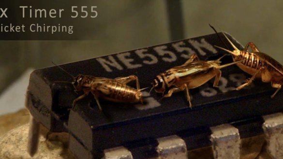
The grasshopper chirping simulator proposed by the author of Instructables under the nickname payam_sbr is made on two microcircuits: 556 and 555. The first of them is two 555 timers (KR1006VI1) in one case, so you can run homemade and on three single chips, only the board will have to be redone.
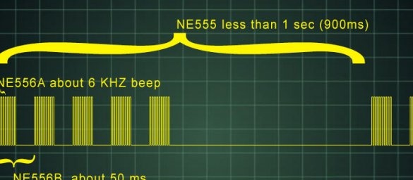
The master draws up a diagram consisting of three multivibrators that differ from each other in the values of the components. Each previous multivibrator controls the next, if you count them from the bottom up. The first sets the frequency of repetition of the packs, the second sets the frequency of repetition of tonal messages in a packet, and the third sets the tone frequency of these packages. The first multivibrator is connected to the second through an inverter on the transistor, the second to the third directly. The signal from the third multivibrator goes to the key power amplifier, and from it to the dynamic head. The key and dynamic head can be replaced with a ready-made module for Arduinocontaining the same components.

The signal generated by the simulator is shown schematically in the graph:
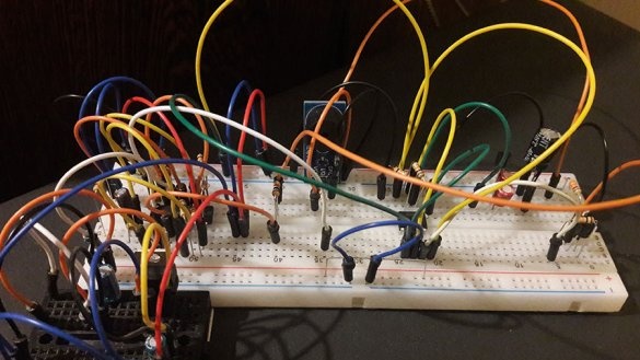
The wizard assembles the circuit on a breadboard type breadboard. Also suitable perfboard, volumetric, surface mounting, depending on your preferences and capabilities.
Then the master performs the same simulator of grasshopper sounds on a printed circuit board. First, design the board itself (source - here):

Then he makes a visualization with components, and most importantly - jumpers, so that when repeating it was clear where they are located:
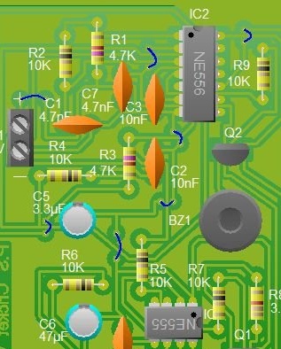
And without them:
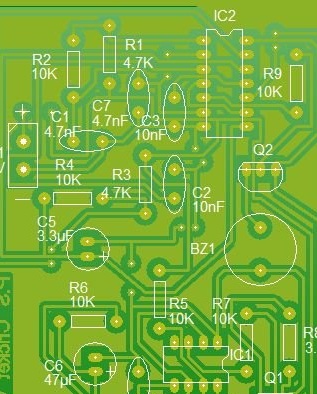
The master does not give a photo of the finished second version of the simulator.
In this video, the simulator in the first version (i.e., on the breadboard) is not configured correctly: the tonal sendings are too long, which makes it look not so much like a grasshopper as an alarm clock. It is easy to guess that reconfiguration requires the second of three generators.

