
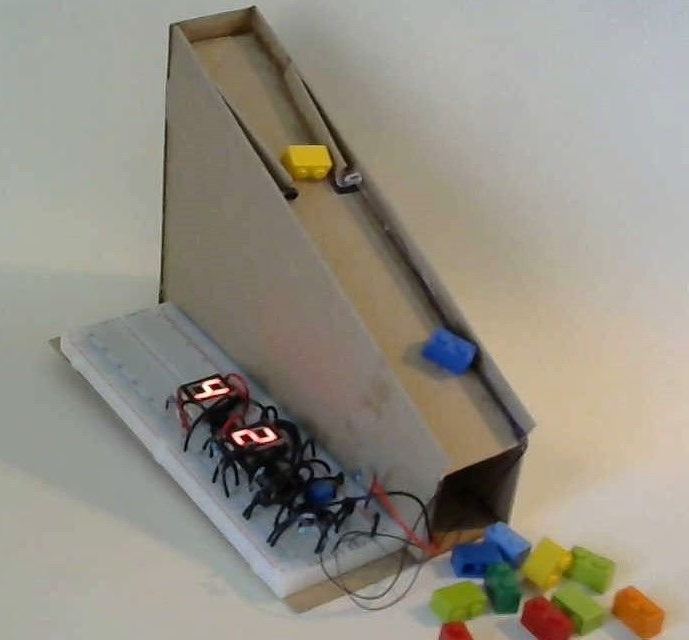
The author of Instructables under the nickname Nawielectron proposes to build an existing model a counter of objects similar to those used on conveyors, conveyors. It contains all the nodes of real object counters with optical sensors: an emitter, a photodetector, a comparator, and an actual counter, which is made two-digit in the model for simplicity.
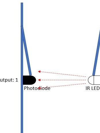
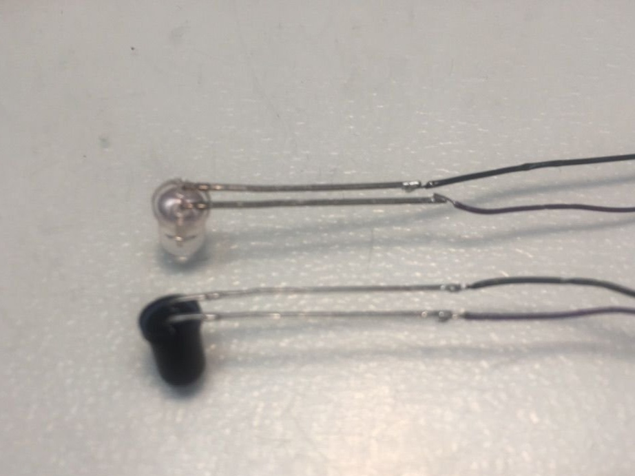
The device’s sensor is an optocoupler with an open optical channel. Such optocouplers can work on reflection and beam overlap. The second option is selected here:
Scheme homemade shown below:
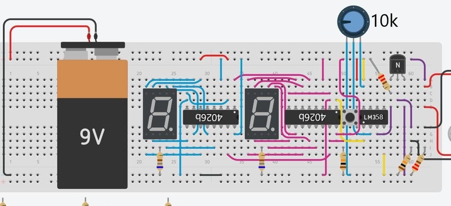
The IR diode is connected to the power source through a 220 Ohm resistor. Photodiode - through a 10 kΩ resistor. Together with this resistor, the photodiode forms a voltage divider. When the photodiode is lit, it “drags” it, when it is darkened, as shown in the following figure, it “drags” the resistor.
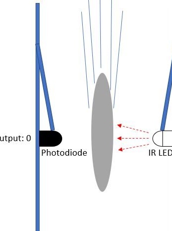
Since the photodiode is located in the upper arm of the divider, when it is darkened, the voltage at the midpoint decreases. Therefore, before applying to the comparator, this voltage is passed through an inverting amplifier on a transistor marked with the letter N. It can be any NPN transistor with parameters and a pinout like 2n2222, BC547, etc. The signal from the output of the divider goes to the base of the transistor, its emitter is connected directly to the minus of the power source, and the collector is connected to the plus via a 220 Ohm load resistor. From the junction of the resistor with the collector of the transistor, the inverted signal is fed to the non-inverting input of the comparator. The inverting input of the same comparator receives voltage from the moving contact of a variable resistor of 10 kOhm. This allows you to adjust the threshold of the comparator.
At the output of the comparator, the signal is no longer analog, but discrete. It is fed to the input of the low-order counter. From the overflow output of this counter, the signal goes to the input of the high-order counter. The reset button is pulled 10 kΩ down by the resistor. When it is depressed, a logic zero is applied to the reset inputs of both counters.When pressed - one, which leads to their reset. Also, the counter is reset without pressing a button when overflowing both digits.
The indicators were used with a common cathode, to simplify the circuit, the master included one 680 Ohm resistor in the cathode circuit of each of the indicators. This made it possible to reduce the number of resistors by 7 times, but the brightness depends on the number of simultaneously connected segments.
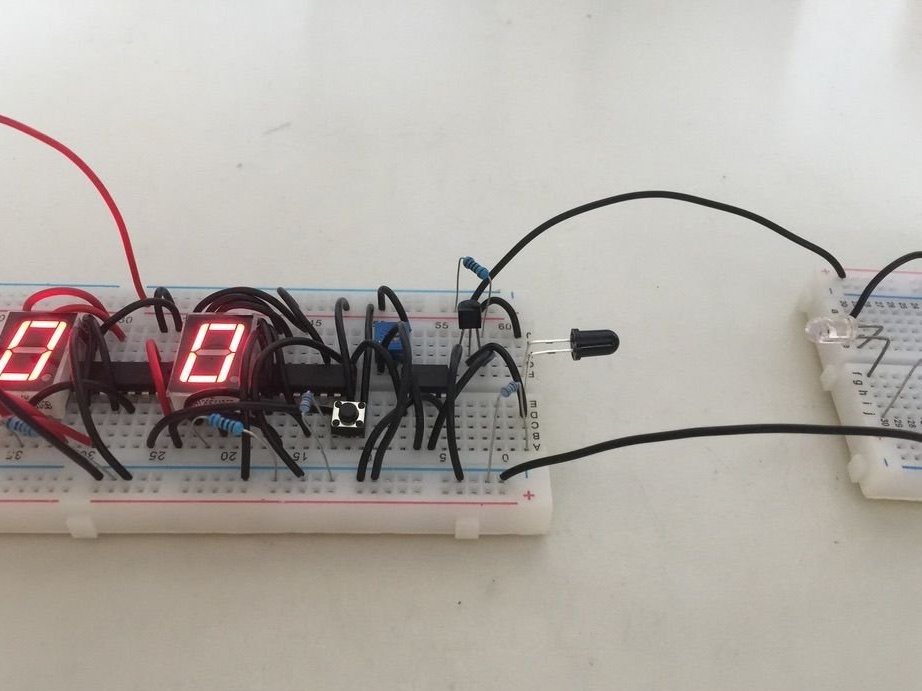
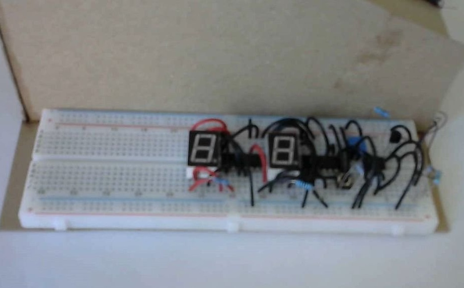
The wizard collects the circuit:
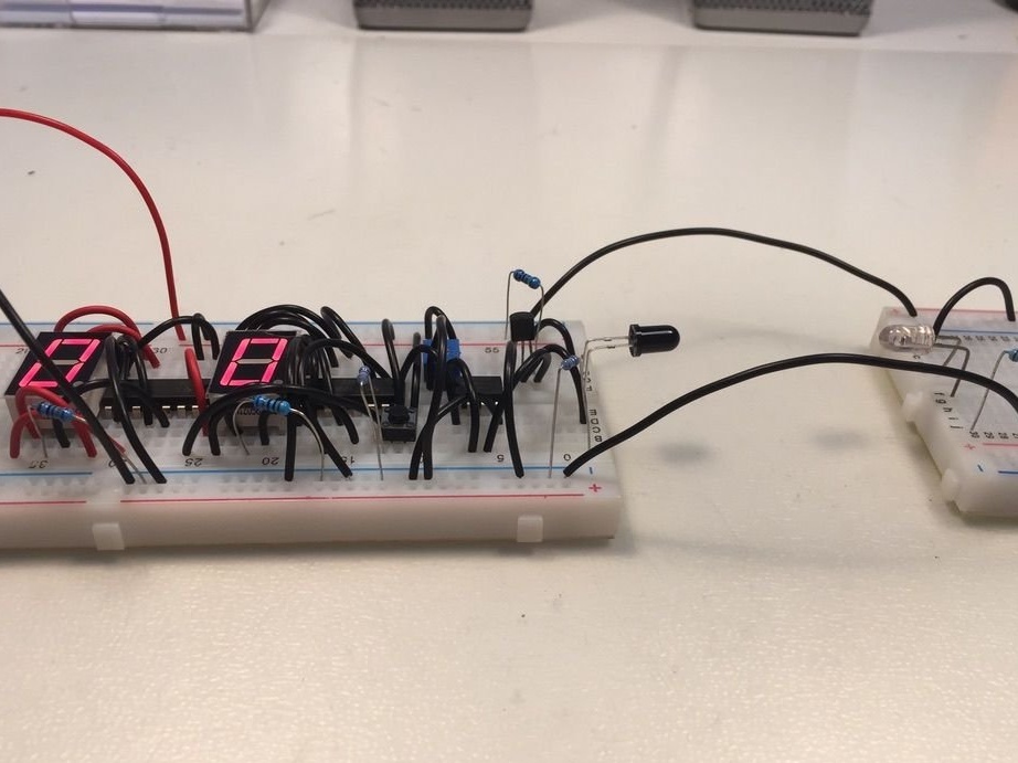
Includes:
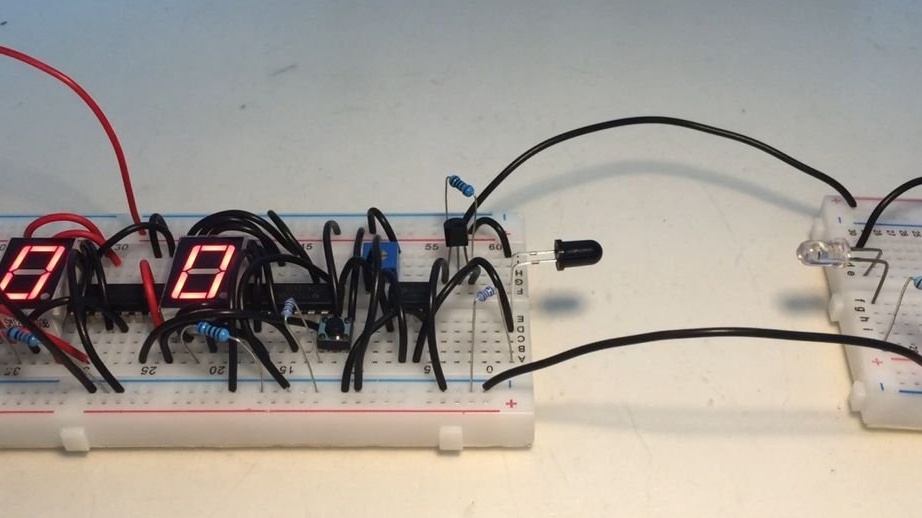
Checks its response to the overlap of the optical channel of the optocoupler:
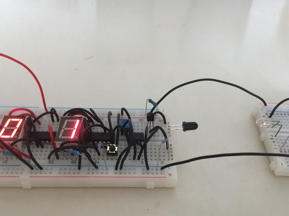
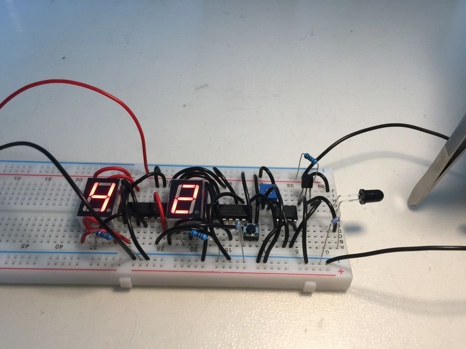
And at the press of a reset button:
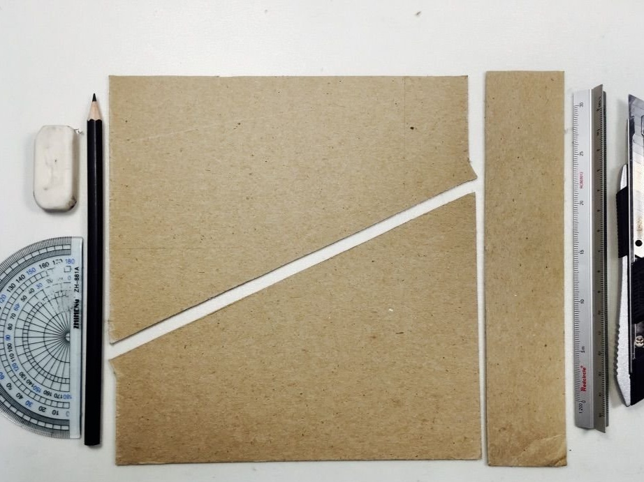
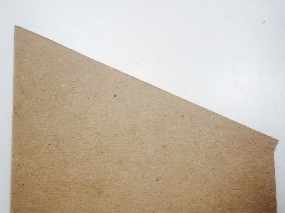
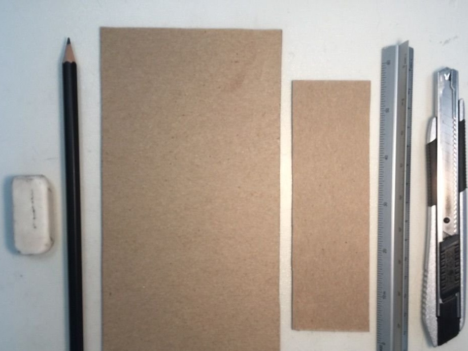
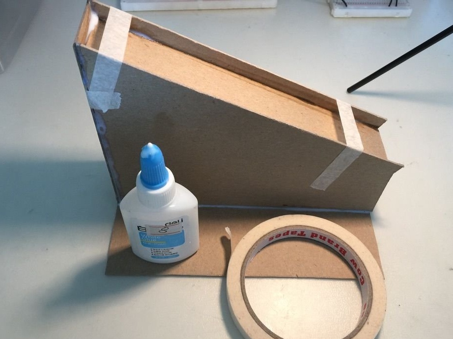
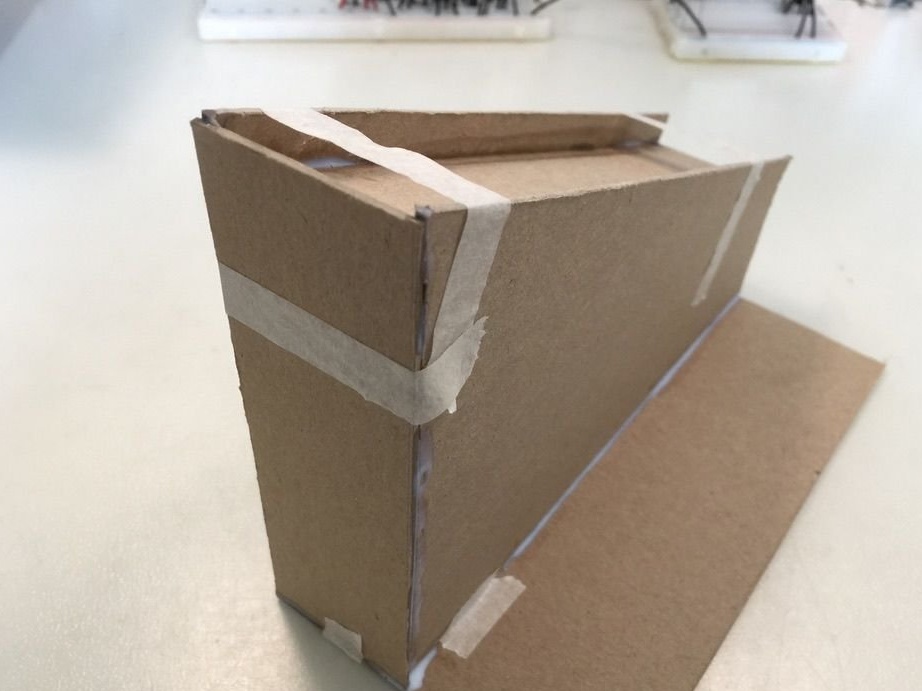
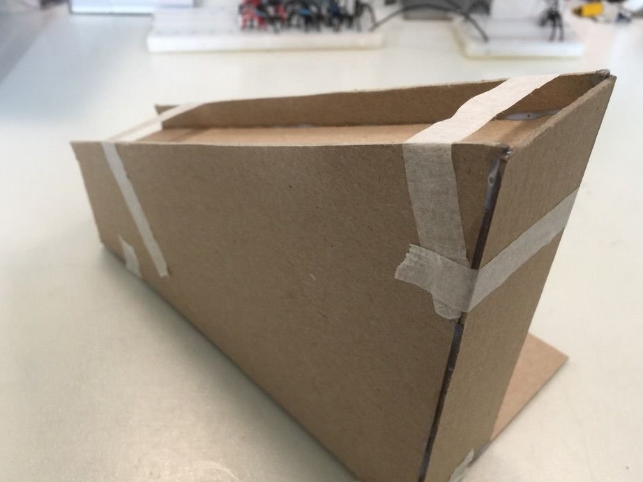
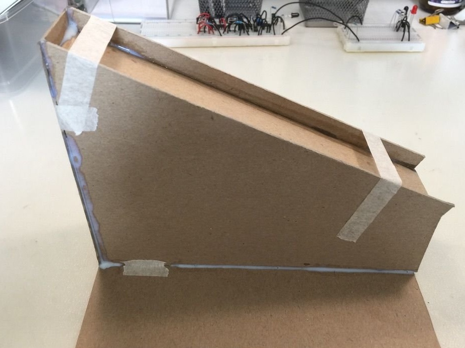
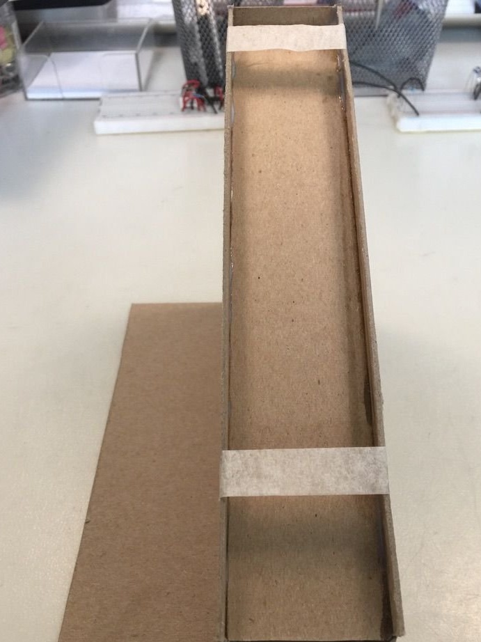
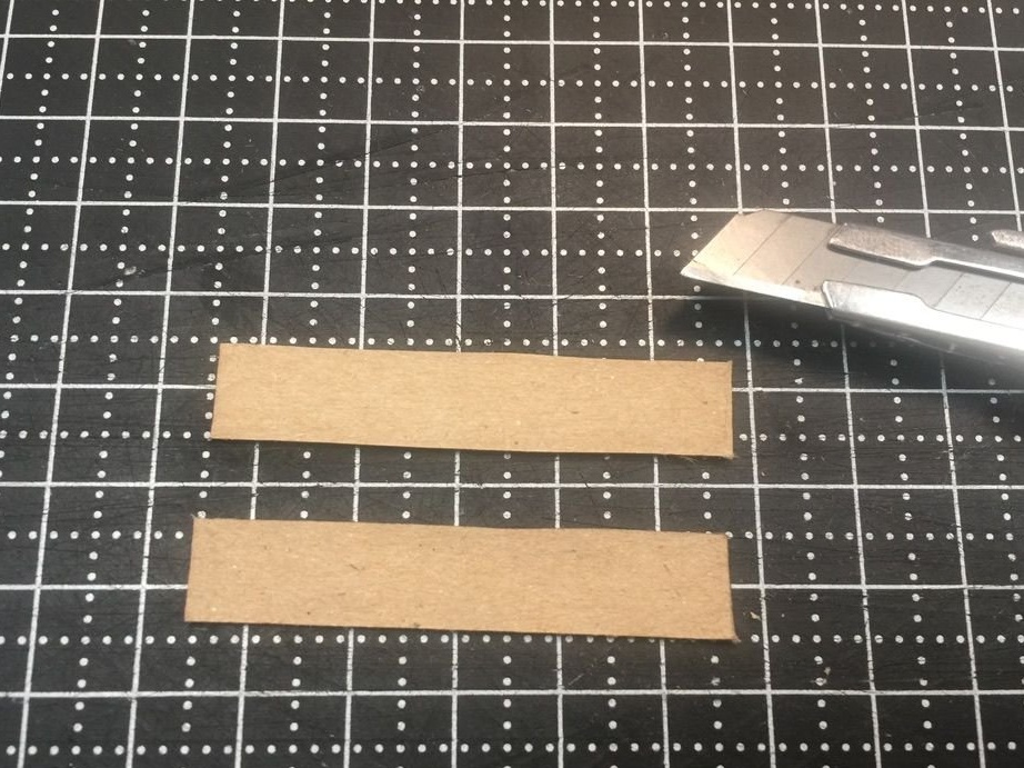
Making sure that electronics works as expected, the master cuts out the details for the inclined plane, on which the counted objects will roll:
Glues the inclined plane with PVA glue, during the hardening of which it additionally fixes everything with masking tape:
After that, remove the masking tape and glue the breadboard to the shelf provided for it:
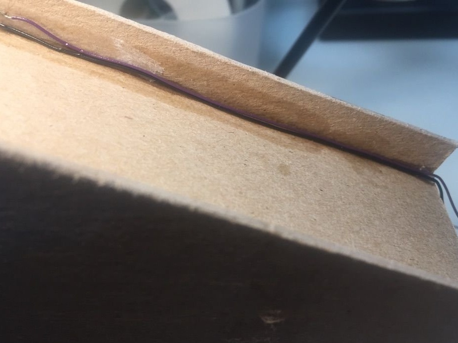
Solder the conductors connecting them to the IR diode and photodiode:
Installs them in the places intended for them:
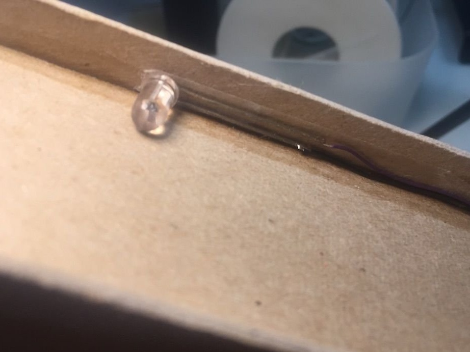
Conductors displays so that the counted objects do not touch them:
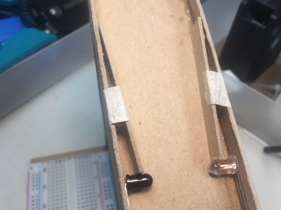
And so that these objects do not touch the IR diode and photodiode, it makes guides:
Which places on an inclined plane as follows:
If even when the optical channel of the optocoupler is blocked, a little reflected radiation is incident on the photodiode, black paper can be glued around the IR diode. View of the finished meter:
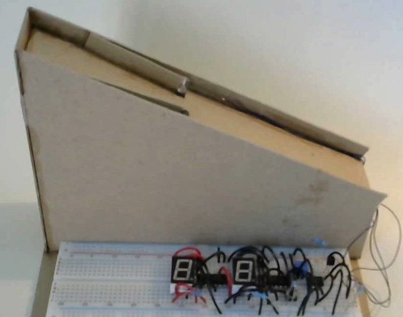
He is in action: