

Recently, I became interested in the assembly of linear voltage stabilizer circuits. Such schemes do not require rare details, and the selection of components and tuning also does not cause any special difficulties. This time I decided to assemble a linear voltage stabilizer circuit on the "regulated zener diode" (microcircuit) TL431. TL431 acts as a reference voltage source, and the power role is played by a powerful NPN transistor in the TO -220 package.
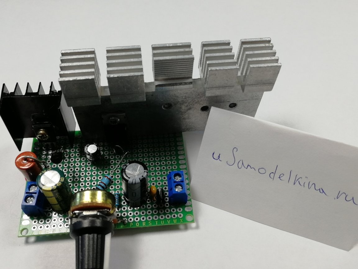
With an input voltage of 19V, the circuit can serve as a source of stabilized voltage in the range from 2.7 to 16 V at a current of up to 4A. The stabilizer is designed as a module assembled on a breadboard. As follows:
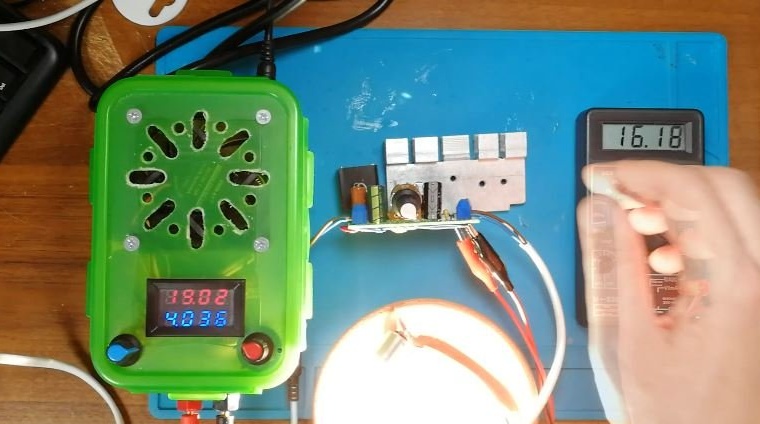
Video:
The stabilizer requires a DC power supply. It makes sense to use such a stabilizer with a classic linear power supply, consisting of an iron transformer, a diode bridge and a large capacitor. The voltage in the network can vary depending on the load and as a result, the voltage at the transformer output will change. This circuit will provide a stable output voltage with a varying input. It must be understood that the stabilizer of the lowering type, as well as in the circuit itself, drops 1-3 V, so the maximum output voltage will always be less than the input.
In principle, switching power supplies can be used as a power supply for this stabilizer, for example, from a 19 V laptop. But in this case, the role of stabilization will be minimal, because factory switching power supplies and so on output stabilized voltage.
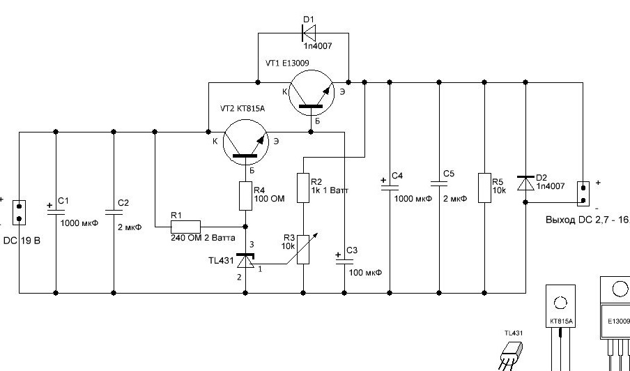
Scheme:
Selection of components
The maximum current that the TL431 chip can pass through itself, according to the documentation, is 100 mA. In my case, I limited the current with a margin to about 80 mA using the resistor R1. It is necessary to calculate the resistor according to the formulas.
First you need to determine the resistance of the resistor. At a maximum input voltage of 19 V, according to Ohm's law, the resistance is calculated as follows:
R = U / I = 19V / 0.08A = 240 Ohm
It is necessary to calculate the power of the resistor R1:
P = I ^ 2 * R = 0.08 A * 0.08 A * 240 Ohms = 1.5 Watts
I used a Soviet 2-watt resistor
Resistors R2 and R3 form a voltage divider that “programs” TL431, and the resistor R3 is variable, which allows you to change the reference voltage, which is then repeated in a cascade of transistors. I used R2 - 1K ohm, R3 - 10K ohm. The power of resistor R2 depends on the output voltage. For example, with an output voltage of 19V:
P = U ^ 2 / R = 19 * 19/1000 = 0.361 watts
I used a 1 watt resistor.
Resistor R4 is used to limit the current based on the transistor VT2. It is better to select the rating experimentally, controlling the output voltage. If the resistance is too large, this will significantly limit the output voltage of the circuit. In my case, it is 100 Ohms, any power is suitable.
As the main power transistor (VT1), it is better to use transistors in the TO - 220 or more powerful case (TO247, TO-3). I used transistor E13009, purchased on Ali Express. Transistor for voltage up to 400V and current up to 12A. For such a circuit, a high-voltage transistor is not the most optimal solution, but it will work fine. The transistor is most likely fake and 12 A will not stand, but 5-6A is quite. In our circuit, the current is up to 4A, therefore, suitable for this circuit. In this scheme, the transistor must be able to dissipate power up to 30-35 watts.
The power dissipation is calculated as the difference between the input and output voltage multiplied by the collector current:
P = (U output -U input) * I collector
For example, the input voltage is 19 V, we set the output voltage to 12 V, and the collector current is 3 A
P = (19V-12V) * 3A = 21 watts - this is a completely normal situation for our transistor.
And if we continue to reduce the output voltage to 6V, the picture will be different:
P = (19V-6V) * 3A = 39 watts, which is not very good for a transistor in a TO-220 package (you also need to take into account that when the transistor is closed, the current will also decrease: by 6V the current will be about 2-2.5A, and not 3). In this case, it is better to either use another transistor in a more massive case, or reduce the difference between the input and output voltage (for example, if the power supply is transformer, by switching the windings).
Also, the transistor must be rated for a current of 5A or more. It is better to take a transistor with a static current transfer coefficient of 20. The Chinese transistor fully meets these requirements. Before sealing in the circuit, I checked it (current and power dissipation) on a special stand.
Because TL431 can produce a current of not more than 100 mA, and to power the base of the transistor requires more current, you will need another transistor, which will amplify the current from the output of the TL431 chip, repeating the reference voltage. For this, we need a transistor VT2.
Transistor VT2 must be able to supply sufficient current to the base of transistor VT1.
It is possible to roughly determine the required current through the static current transfer coefficient (h21e or hFE or β) of the transistor VT1. If we want to have a current of 4 A at the output, and the static current transfer coefficient VT1 is 20, then:
I base = I collector / β = 4 A / 20 = 0.2 A.
The static current transfer coefficient will vary depending on the collector current, so this value is indicative. Measurement in practice showed that it is necessary to supply about 170 mA to the base of transistor VT1 so that the collector current is 4A. The transistors in the TO-92 package start to warm up noticeably at currents above 0.1 A, so in this circuit I used the KT815A transistor in the TO-126 package. The transistor is designed for current up to 1.5A, the static current transfer coefficient is about 75. A small heatsink for this transistor will be appropriate.
Capacitor C3 is needed to stabilize the voltage on the basis of the transistor VT1, the nominal value is 100 μF, the voltage is 25V.
Filters from capacitors are installed at the output and input: C1 and C4 (electrolytic at 25V, 1000 μF) and C2, C5 (ceramic 2-10 μF).
The diode D1 serves to protect the transistor VT1 from reverse current. Diode D2 is needed to protect against a transistor when supplying collector motors. When the power is turned off, the engines spin for a while and in the braking mode work as generators. The current generated in this way goes in the opposite direction and can damage the transistor.The diode in this case closes the motor to itself and the current does not reach the transistor. Resistor R5 plays the role of a small load for stabilization in idle mode, a nominal value of 10k Ohm, any power.
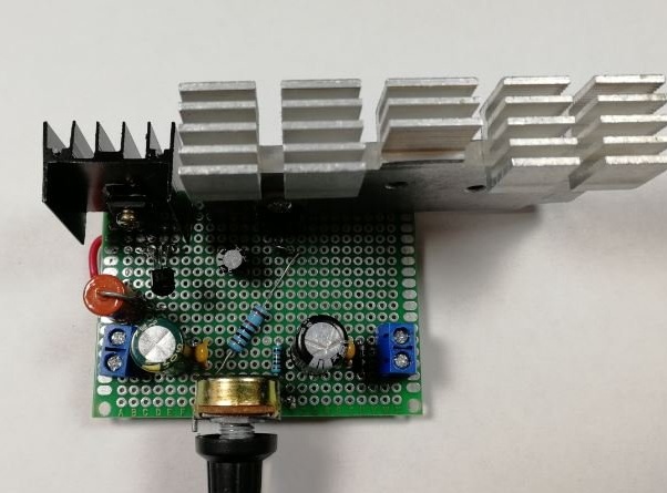
Assembly
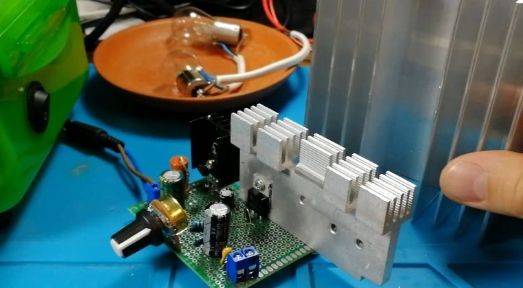
The circuit is assembled as a module on a breadboard. I used a radiator from a switching power supply.

With a radiator of this size, you should not load the circuit as much as possible. With a current of more than 1 A, it is necessary to replace the radiator with a more massive one, blowing with a fan will also not hurt.
It is important to remember that the greater the difference between the input and output voltage and the greater the current, the more heat is generated and the more cooling is needed.
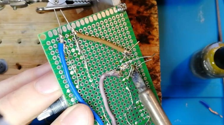
It took about an hour to solder. In principle, it would be a good form to make a board using the LUT method, but since I only need a board in one copy, I did not want to waste time designing the board.
The result is such a module:
After assembly, I checked the characteristics:
The circuit has virtually no protection (meaning that there is no short circuit protection, reverse polarity protection, soft start, current limitation, etc.), so you need to use it very carefully. For the same reason, it is not recommended to use such schemes in "laboratory" power supplies. For this purpose, ready-made microcircuits in the TO-220 package are suitable for currents up to 5A, for example, KR142EN22A. Or at least for this circuit, you need to make an additional module for protection against short circuit.
The circuit can be called classical, like most linear stabilizer circuits. Modern pulse circuits have many advantages, for example: higher efficiency, much less heating, smaller dimensions and weight. At the same time, linear circuits are easier to master for beginner hams, and if the efficiency and dimensions are not particularly important, they are quite suitable for supplying devices with stabilized voltage.
And of course, nothing beats the feeling when I powered some device from a home-made power source, and linear circuits for beginner hams are more accessible, whatever one may say.