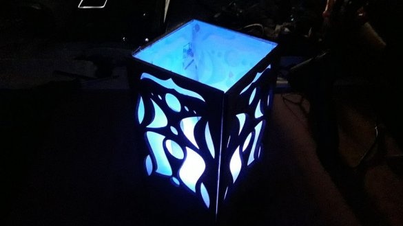
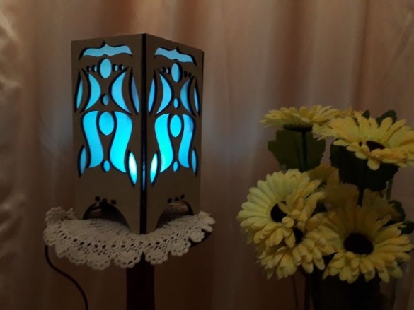
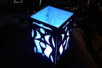
The author made a flickering flashlight in a case from parts cut out by a laser. Inside, a flame simulator is installed, consisting of a fan and pieces of light fabric, as well as a device for smooth color change on the Digispark board and RGB LEDs. If you only need to simulate a flame without changing colors, just white LEDs with a color temperature of 2700 K will do.
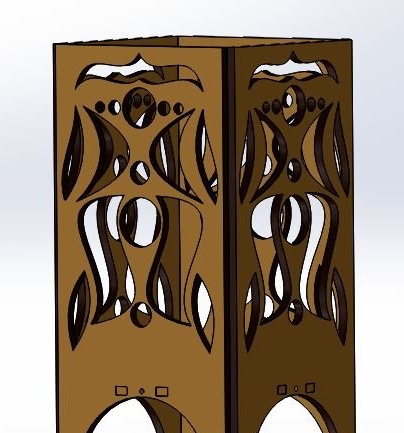
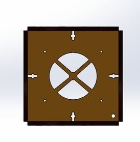
Work on homemade the wizard starts with designing the case. It saves the result in DXF format, intended for the exchange of information between various CAD systems, packs it in a RAR archive and uploads it here. The versatility of the format allows you to apply for laser cutting in almost any company that provides this service. In the author's version, the body parts are cut from fiberboard 5 mm thick, but plywood and painted plexiglass will do. Here are some renderings of the future case:

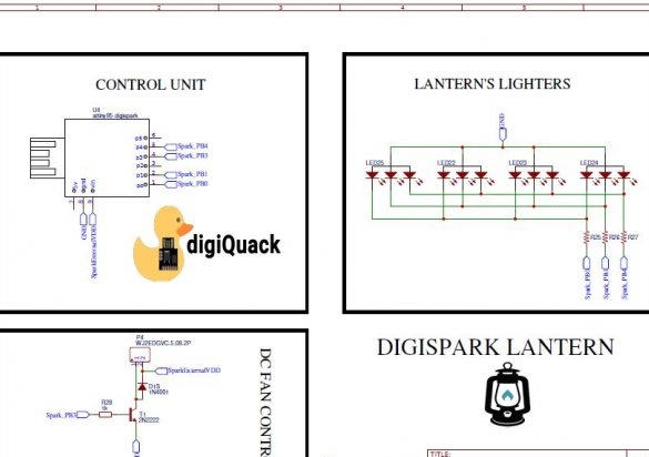
Having decided on the case, the master takes up electronic part of the lantern. It consists of the Digispark board itself, four parallel-connected RGB LEDs with three resistors, as well as a fan control key, consisting of a transistor, a resistor to limit the current of its base and a protective diode connected in reverse polarity:
In fact, a diode is not needed here, since the motor in the fan is not a collector, its windings are switched by an integrated microcircuit with Hall sensors, transistors and self-induction protection elements. In old fans, transistors are external, but this does not change the essence.
Components located outside Digispark are placed by the wizard on the board ordered in JLCPCB. Gerber format files necessary for its production are also in the RAR archive hereso that the reader can order the board anywhere, but at least make the house LUTom. You can do without it, connecting everything that is outside the Digispark'a, mounted or volumetric installation. But the board is prettier:
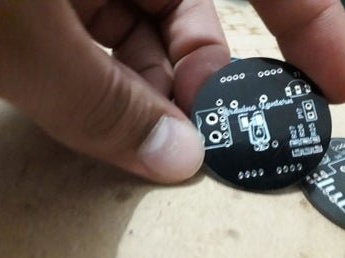
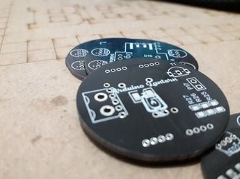
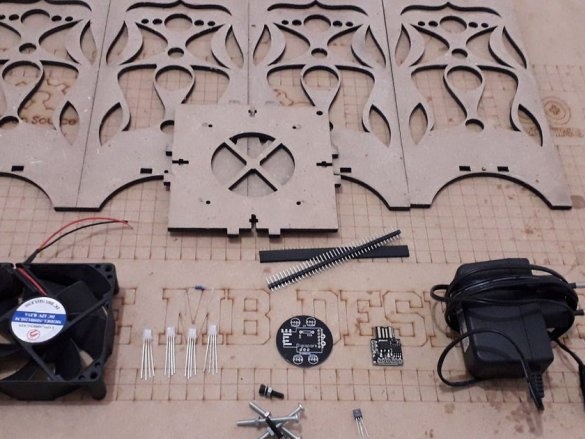
So, everything necessary for the assembly of the lamp arrived: parts of the case, and a fan, and electronic components, and a power supply.
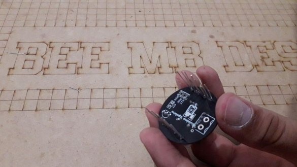
The wizard takes over the assembly of the board connected to Digispark.Please note: the entire flashlight is powered by 12 V, so on Digispark you need to choose the one of the power inputs that is designed for unstabilized voltage from 7 to 35 V.
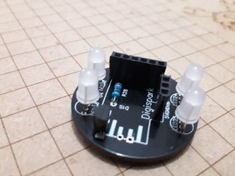
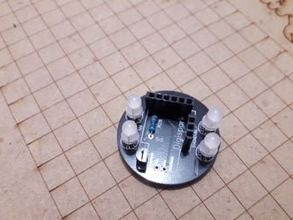
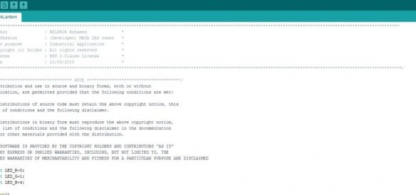
Now the master recalls that he is also a programmer, and takes up Arduino IDE This screenshot shows the beginning of the program with the text of the BSD license (option of two conditions) in the comments:
Well, all the firmware, again packaged in the RAR archive, lies here. Her master pours into Digispark, then collects from it and ext. boards with the help of two combs located at right angles, a "sandwich":
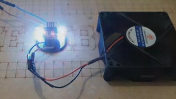
It connects the fan and power supply, checks how everything works:
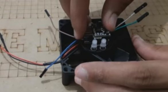
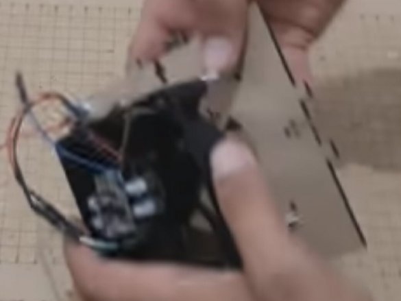
Glues a “sandwich” from the circuit boards to the fan motor:
And all this screws to the bottom of the case cut by the laser so that the fan blows air up, and the LEDs shine there. It is important to provide a small gap between the bottom and the fan with washers so that nothing prevents the blades from rotating.
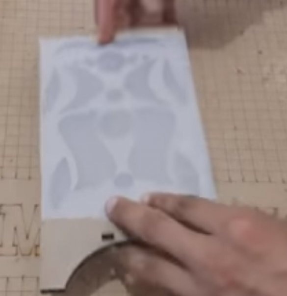
Tape the walls of the case from the inside with a thin, well-transmitting paper:
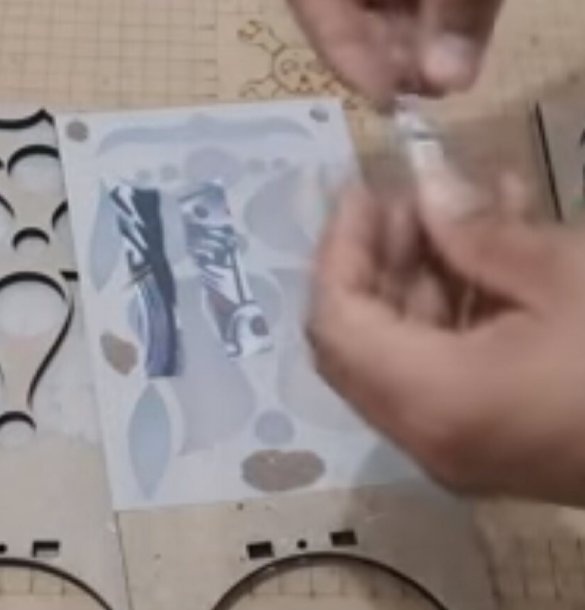
And to it glues pieces of light tissue, which have to oscillate in the air stream:
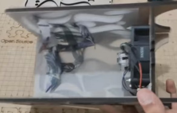
Assembles the body. Its design is such that the bottom is raised above the table so that the fan can take in air, and the recesses below on the side walls contribute to this:
Result:
The assembly process and the operation of the device on video:
This design can be simplified in two ways. The first is to abandon a smooth color change, leaving only a mechanical flame simulator. Then Digispark becomes unnecessary. The second - on the contrary, implement software and imitation of the flame, which will make it possible to abandon the mechanics.

