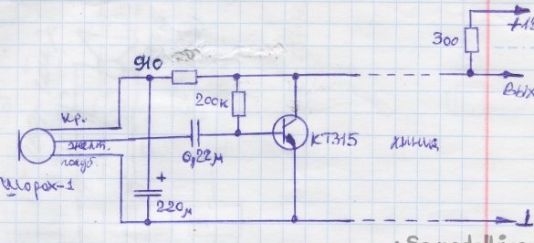
It may be necessary to transmit the signal from the microphone without interference over a long distance, using an unshielded, inexpensive wire.
I designed and manufactured a large number of microphones with an amplifier on one board. These products have proven themselves in work.
On two wire lines of inexpensive wire such as "noodles" and the like, I was able to transmit high-quality sound to a distance of 1 km. In this case, the device was powered by the same wire. Often used by someone - the previously laid wires of telephone lines, alarm lines that were no longer needed.
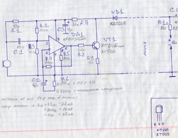
Circuit diagram.
Description of the circuit.
The supply voltage from the source through the line and the diode overvoltage protection diode VD1 is supplied to the collector of the output transistor VT1, an economical operational amplifier DA1 and an electret microphone.
The R7C3 filter is included in the positive power cable, it is needed for the proper operation of the microphone and operational amplifier. The output transistor, which is a current amplifier, is turned on before the filter. Thus, it is possible to separate the sound signal and the power supplied by the same wires.
The electret microphone is powered as standard through resistor R1. From it, the signal is fed to the non-inverting input of the operational amplifier through an isolation capacitor C1. This capacitor slightly attenuates possible mains interference. The board does not need a metal shielding case. Often put in any suitable plastic box, such as those used in electrics. The voltage from the divider on the resistors R2 R3 equal to half the supply voltage is also supplied here.
The amplifier is covered by negative feedback. R4 R6 C2. It sets the mode for direct and alternating current, gain and frequency response, weakening possible pick-ups of 50 Hz. Resistor R5 sets the micropower operation mode of the operational amplifier for minimal current consumption.
From the output of the microcircuit, an audio signal is supplied to the base of the output transistor.
The circuit can work in different ways.
1 to low impedance headphones
2 per speaker 50 ohms.
3 to the recording device, for this an additional circuit is provided from the resistor R10 and the capacitor C4.
In case 3, the signal transmission range is the longest.
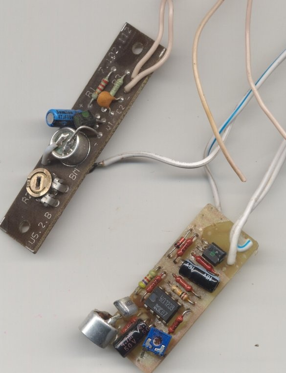
In practice, I compared the characteristics of my product with industrial designs. All of them were inferior.For example, by transmission distance. Caught some microphones with automatic gain control. At the slightest loud sound, the microphone “locked” for a few seconds, this is bad. In the photo next to my microphone and the factory microphone, which I dismantled from the cab of the decommissioned elevator. It is larger in size, the gain is less, the elevator can only be called when you get stuck.
Consumption depending on the line resistance at a supply voltage of 12 volts is indicated in the diagram. The range of transmitted frequencies is sufficient for very high-quality voice transmission. The transmission distance is up to one kilometer. No interference, no interference at the output (often a line was laid next to power cables). In the circuit, various electret microphones of different types and sizes are tested. They all worked, the difference was in sensitivity. It can be adjusted by selecting R1 and R6. In the board shown not a photo, there is a tuning R6.
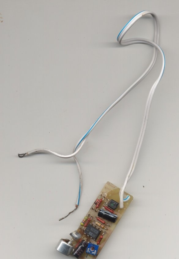
Photo of the finished board from above
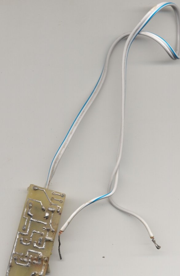
Photo of the finished board below
PCB drawing
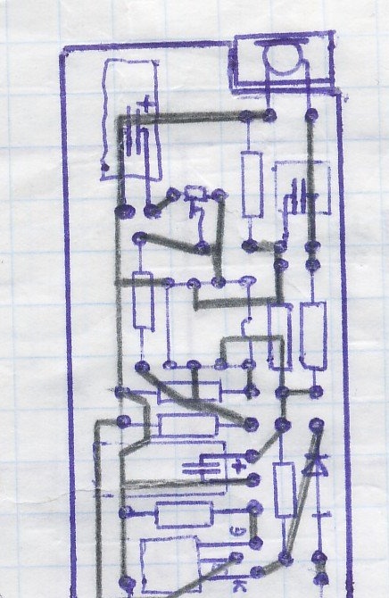
Examples of application of this device.
To control the sound environment in the room when the guard is in another room.
For alarm systems based on the sound principle.
For voice announcements in broadcast systems when the amplifier is in another room.
I also made a simplified version of the product, but its characteristics are much worse.

