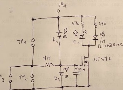
Name of this e candles made by the author stands for flame, IR and touch. How to ignite and extinguish it, you can use a real lighter, an infrared remote control, a special home-made infrared lamp, as well as a touch on the touch pads. As can be seen from the diagram, homemade represents a single cell of an electrically erasable ROM:

Such a cell consists of a capacitor and a MOS transistor. Due to the huge input impedance of such a transistor, a capacitor, once charged, may not discharge for a very long time. The state of the cell can be reversed at any time by discharging or recharging the capacitor. This circuit contains fewer components than, for example, an RS trigger.
For touch control in an electronic candle, pairs of pads TP1, TP2 and TP3 are provided. In this case, TP is not a test point, but a touch point. When you touch the first of the pairs of pads, the capacitor is charged through the resistor R1, when you touch the second or third, it is discharged through it. When controlled by infrared rays, the sensors are infrared diodes used as photodiodes. If under the influence of such rays the diode D3 opens, the capacitor is charged, if D4 is discharged.
The MOS transistor controls two LEDs, one of which is infrared, and inside the second there is a control chip that provides flicker. It should not be confused with similar LEDs that smoothly or abruptly change color. The LED, simulating the flickering of a candle, the master placed under the matte cap in the form of a flame from the finished LED candle, from which this diode was taken. And the infrared LED, which turns on simultaneously with the flickering one, shines on the same LED used as a photodiode that receives the turn-on signal, which compensates for the gradual discharge of the capacitor, albeit very slow.
Two parallel pairs of sensor pads are needed so that one of them can be placed on the board next to the cap. At this electronic candle you can put out a fake "flame" by grabbing it with your fingers, which is impossible with a real candle.Let's look at the video how the wizard controls the device in all provided ways:
For the manufacture of the structure, the master takes the following components:
1 transistor IRF512
3 IR diodes
2 resistors at 470 Ohms - to limit the current through an LED that simulates the flame of a candle, and an IR diode to keep the device turned on
1 resistor per 1 megohm - to protect the transistor when touching the touch contacts
1 capacitor per 100 nF - for a memory cell
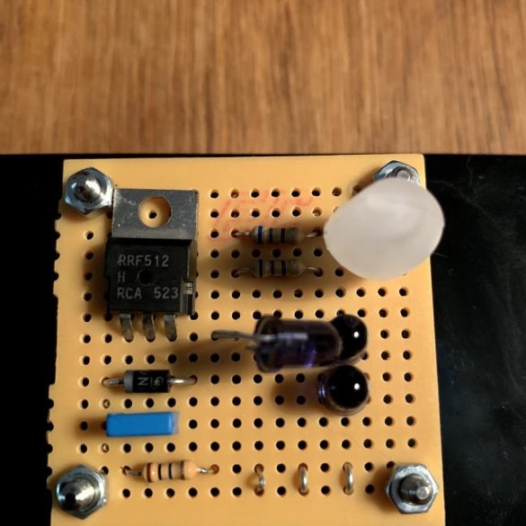
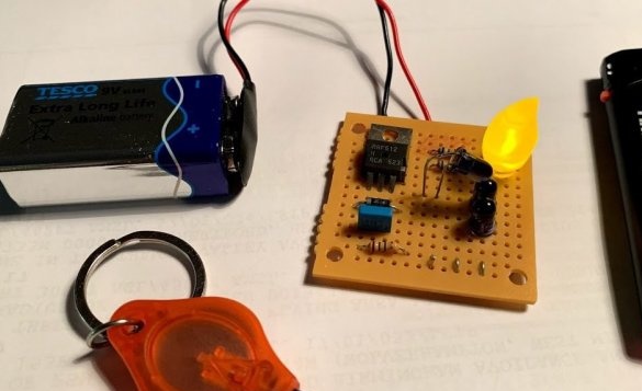
The master collects the circuit on a breadboard such as a breadboard and connects the battery, observing the polarity. A silicon diode is shown on the board, not shown in the diagram, its purpose is not disclosed, but it is clear that it is needed to protect against reverse polarity. Nearby in the photo are two sources of infrared rays for controlling a candle: a lighter and an infrared lamp. You can also use the remote control.
To make an infrared lamp, the master takes a ready-made flashlight, in which of the two batteries leaves only one, and the white LED changes to infrared, observing the polarity. The IR diode has a lower opening voltage, so one battery is more than enough. When reassembling the flashlight, it is important to ensure that the battery is not shorted in the depressed or depressed position.
In order to blow out an electronic candle like a real one, you need to connect a simple flow sensor consisting of a point contact and a flexible metal plate in parallel to the lower touch contacts. If you blow on the plate, it will bend, come into contact with the point contact, and the capacitor will be discharged.


