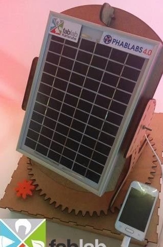
A heliostat, this device is able to rotate a mirror (in this case, the solar panel) so as to direct the sun's rays constantly in one direction, despite the visible daily movement of the Sun.
In this article, we will get to know how such a device works and how it can be manufactured. This heliostat is able to accumulate solar energy, which can then be used, for example, to charge a mobile phone.
Tools and materials:
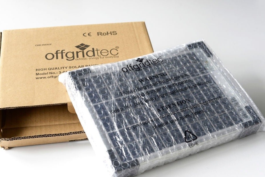
- Solar panel Offgridtec 5W 12V;
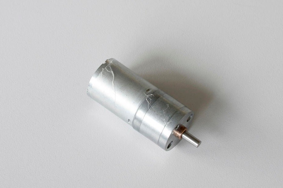
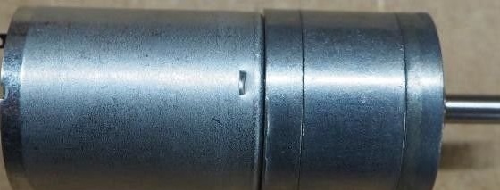
- DC motor V-TEC 6V Mini 25D with gear 177 rpm;
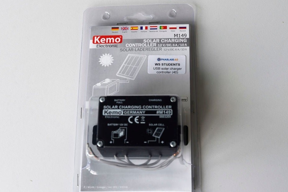
- Adjustable power module;
-USB-micro;
-Printed circuit board;
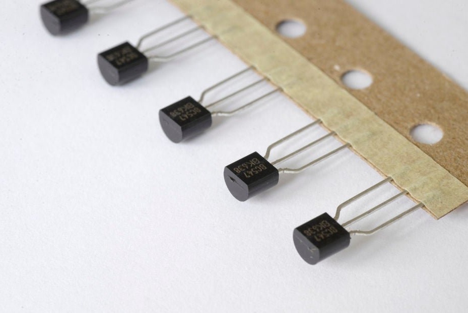
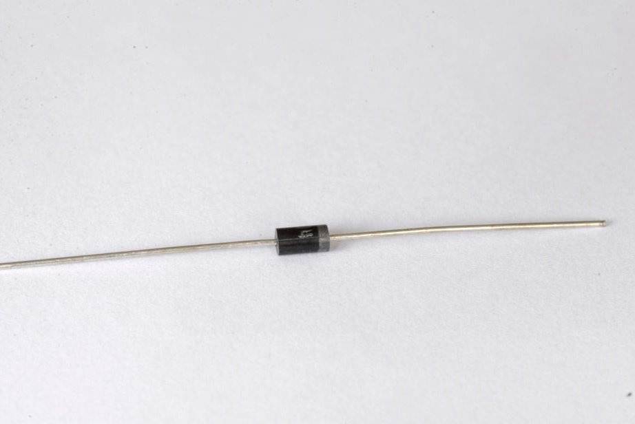
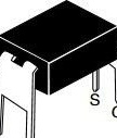
- Transistor IRFD 110 - 2 pcs;
- Transistor IRFD 9120 - 2 pcs;
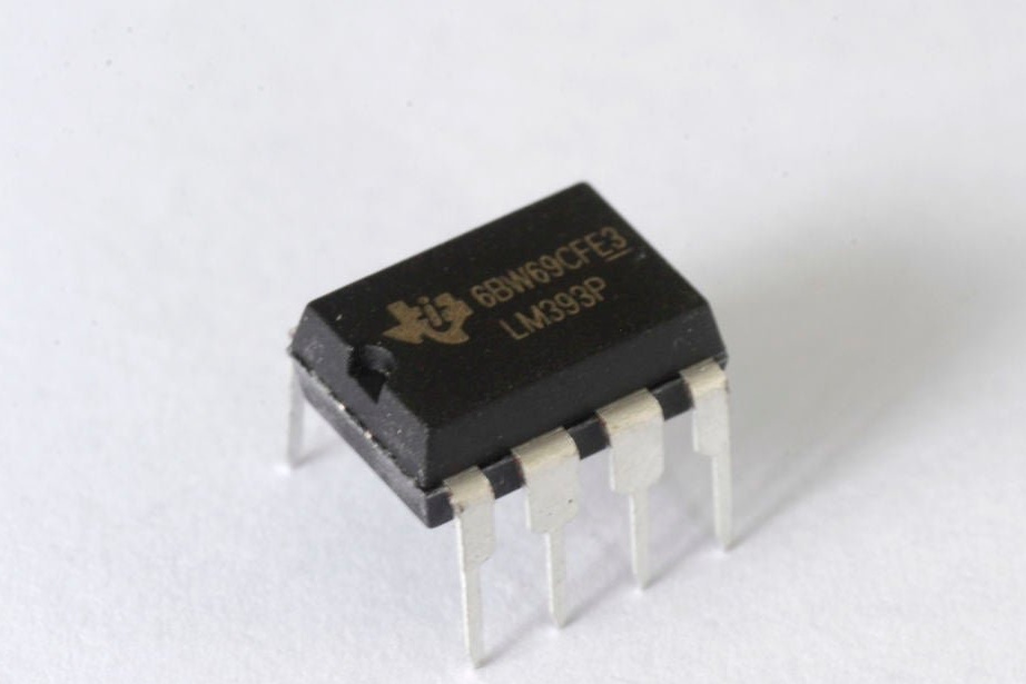
Double comparator, DIP-8;
-Metal film resistors: 330 kOhm - 4 pcs; 1K -1 pcs; 4.7K - 2 pcs;
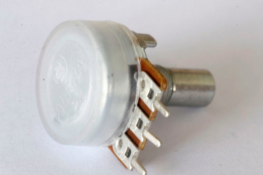
- Potentiometers horizontal, 6 mm, 25 kOhm - 2 pcs;
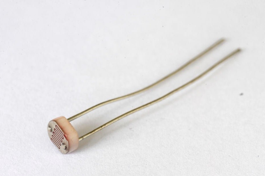
- Photoresistor - 2 pcs;
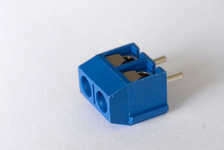
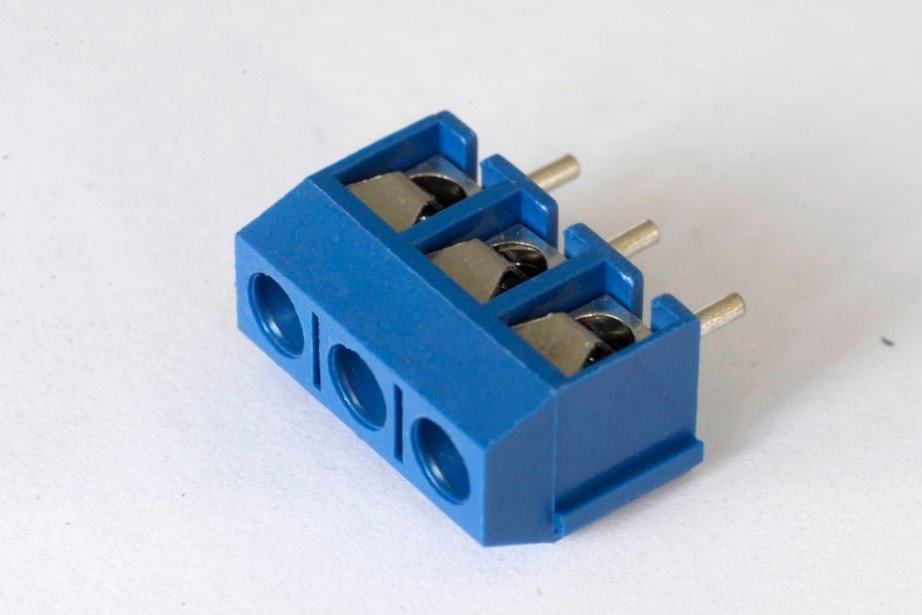
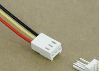
- PCB connector straight, 3-pin;
- PCB connector straight, white 2-pin - 3 pcs;
-Heat-shrink tubing;
-Fasteners;
-Plywood;
-Wire;
-Laser cutter;
-3D printer;
-Soldering iron;
-Pliers;
-Nippers;
- Joiner's glue;
-Screwdriver;
- Thermogun;
-Hacksaw;
- Drill for metal;
- 12 V power supply (or 9 V battery);
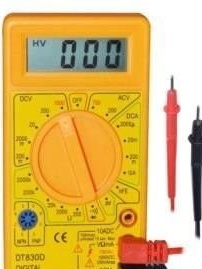
-Multimeter;
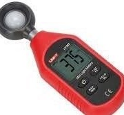
-Luxmeter (optional);
Step One: Theory
In the fight against climate change, renewable energy plays an indispensable role. One of the benefits of renewable energy is that they do not emit greenhouse gases. There are many different renewable energy sources, such as: solar energy, hydropower, wind, marine energy (wave and tide), geothermal energy, bioenergy, hydrogen. A source of energy that can be used over and over again without exhaustion and coming from natural resources is considered renewable energy. If only one percent of the Sahara desert is covered with solar panels, then this will be enough to provide the whole world with electricity.
To use the energy that the sun sends to the earth, it must be converted into another form of energy that can be used more easily, for example, into electricity.
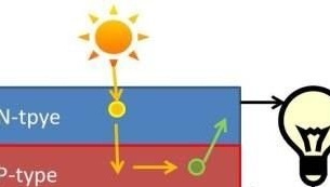
In a photovoltaic cell, sunlight is directly converted to electricity.
A typical photovoltaic cell is made of a semiconductor silicon material.Typically, this type of solar cell consists of two silicon layers: I) n-type silicon and II) p-type silicon. A solar cell generates electricity using sunlight.

Step Two: Preparing Parts
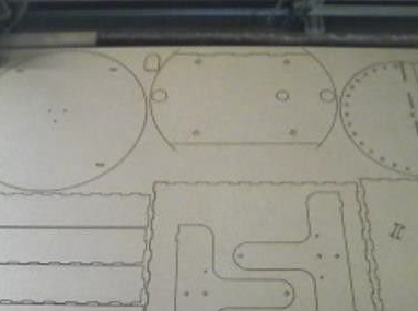
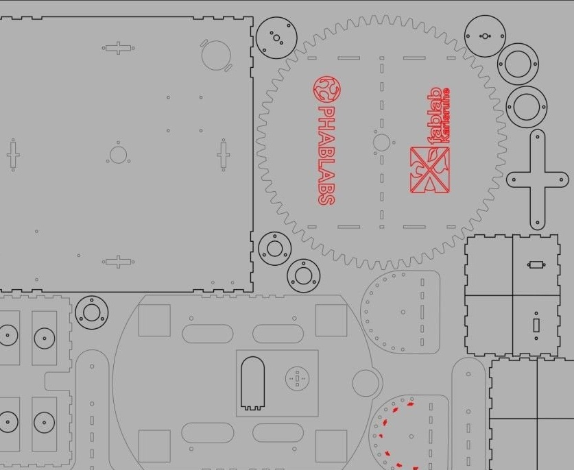
heliostat_all_3mm_comp_v4.svg
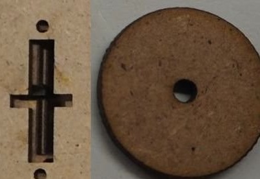
Zahnrad.stl
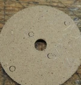
Cut all wood parts with a laser cutter. Print the gear on a 3D printer. Cut a piece of fiber for the axis (length about 1.6 cm).
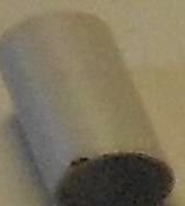
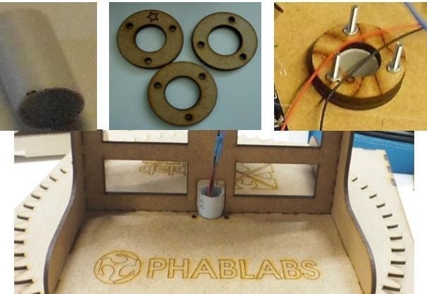
Cut two plastic pipes, one with a diameter of 20 mm and a length of 40 mm (for the axis) and the other with a diameter of 32 mm and a length of 2 cm (for light sensors).
Step Three: Install the Charger
Now you need to assemble the charger.
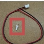
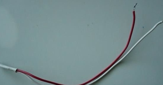
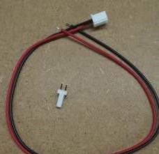
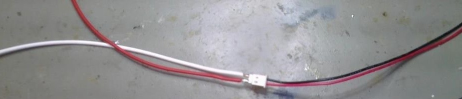
Two wires of 22 centimeters need to be soldered to the two pin connector. Insulate soldering spots.
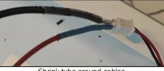
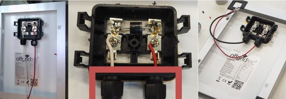
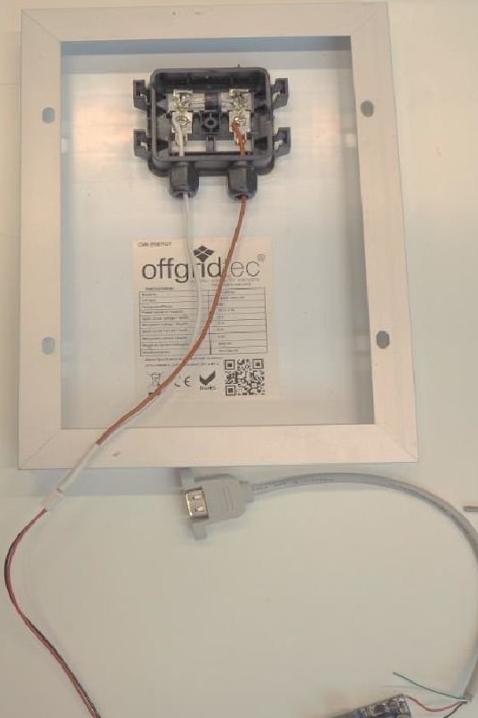
There is a mounting box on the back of the solar panel. The second ends of the wires are fixed to the contacts of the solar panel. At installation it is necessary to observe polarity.
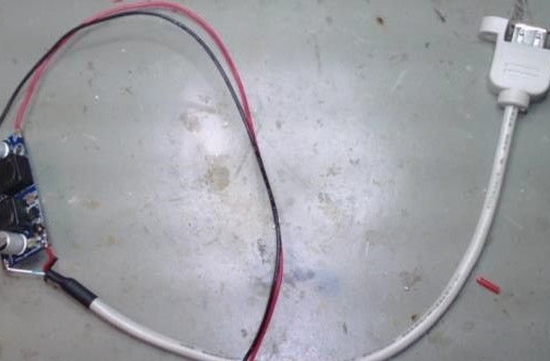
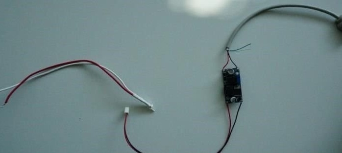
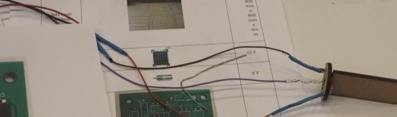
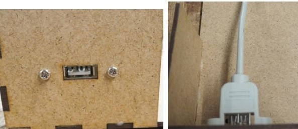
Now we need to connect the solar panel to the voltage regulator, as well as to a USB charger.
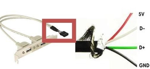
The USB cable has four wires. Need two, black and red. Red is soldered to + the output of the voltage regulator, black to minus. Using an additional wire, we connect the solar panel and the water contacts of the regulator.
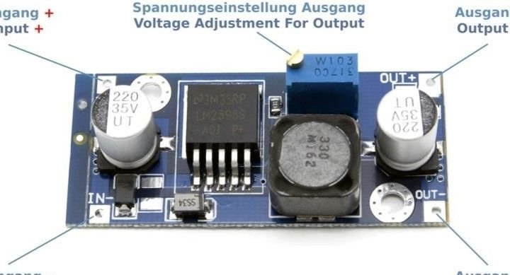
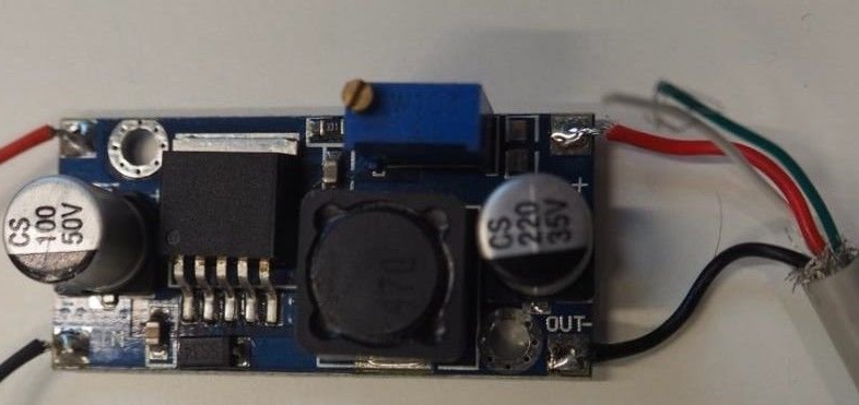
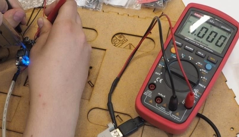
Since the solar cell delivers 12 V and USB devices are only rated at 5 V, the voltage regulator must be set to 5 V.
It is necessary to connect a power source to the input contacts of the regulator and measure the output voltage. If necessary, adjust the voltage to a value of 5 V. using the adjusting screw.
Step Four: PCB
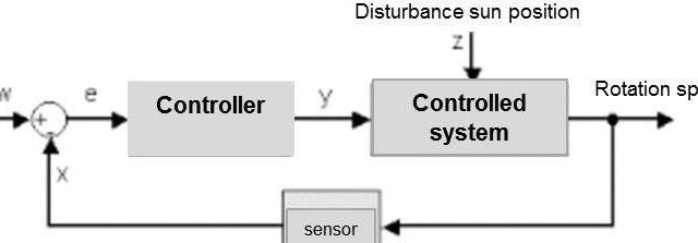
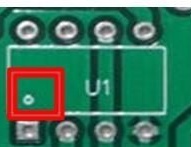
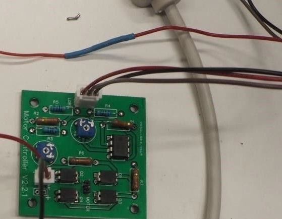
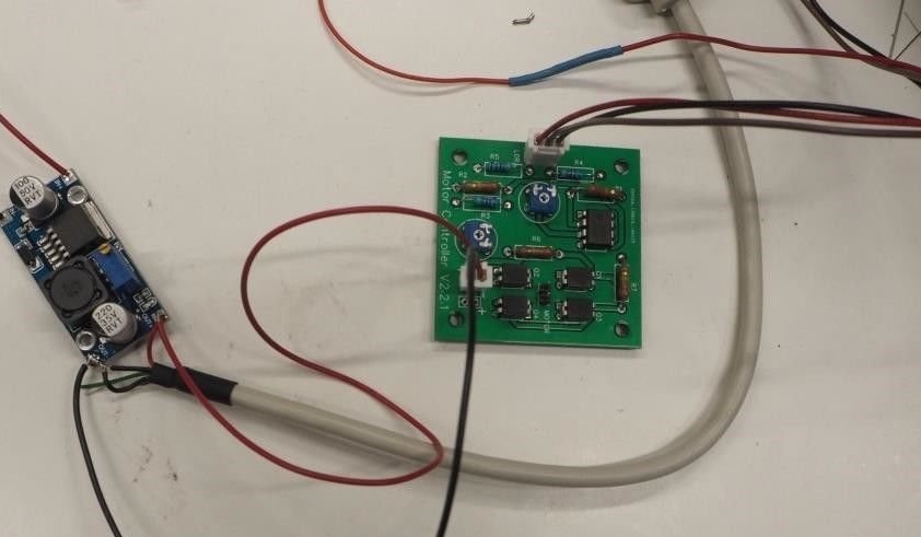
The position of the solar panel relative to the sun will be monitored using two light sensors. The rotation of the panel will be carried out using the engine. Governs it all electronic pay. We mount the board according to the scheme.
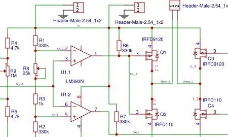
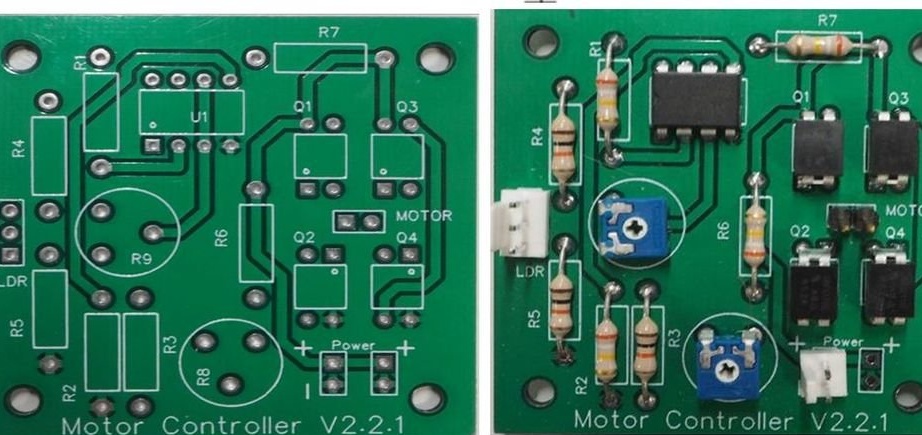
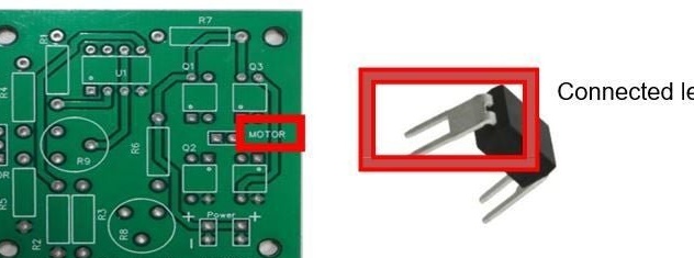
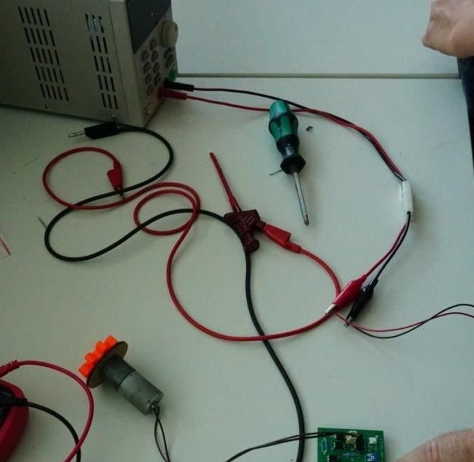
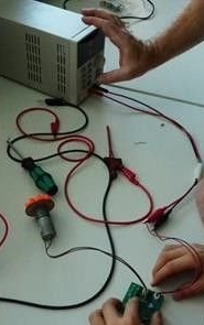
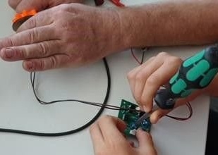
When all electronic components are soldered to the printed circuit board, its functionality should be tested. For the test you will need a power supply, a test motor connected to a 2-pin connector and a screwdriver. It is necessary to check whether the engine rotates, whether power is supplied to it, and whether the engine changes the direction of rotation.
Power up the board. Take a screwdriver and set potentiometer R9 in the middle position. The engine should stop turning. Turn the screwdriver in the other direction to check whether the motor gear also rotates in the opposite direction. If everything works, set the potentiometer to the middle position and turn off the power.
Step Five: Light Sensors
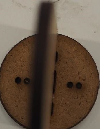
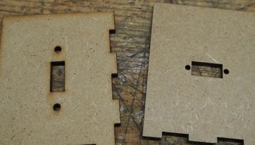
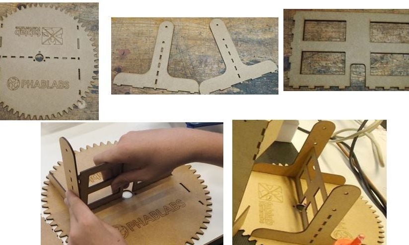
The heliostat must always be perfectly aligned with the sun to receive as much energy as possible. Thus, a mechanism is needed to ensure that the heliostat is always turned towards the sun. This condition is satisfied using photoresistors (or light sensors). Light sensors are mounted above the solar panel. First you need to connect the two wooden parts (as shown in the figure below) and insert the two sensors into the corresponding holes.
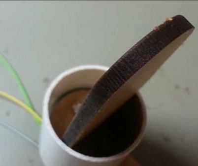
Then place the entire light sensor holder in a round plastic pipe with a diameter of 32 mm and a length of 2 cm. Now you need to connect the photoresistor to the board. Take three cables (each about 60 cm long) and solder them to the sensor contacts.
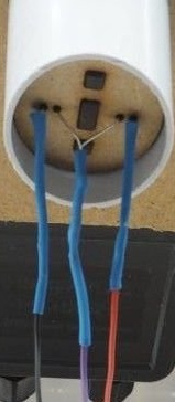
Sensors will be connected to the board using a 3-pin connector.
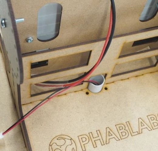
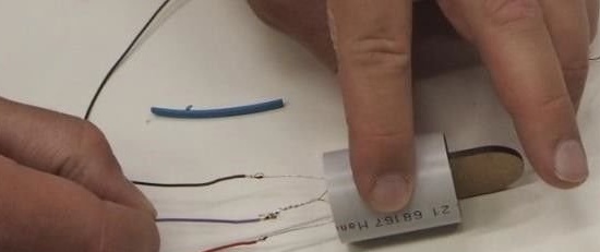
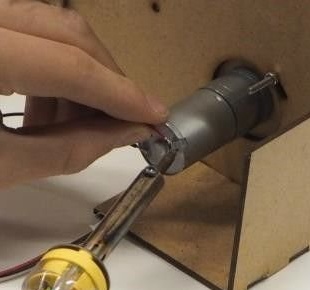
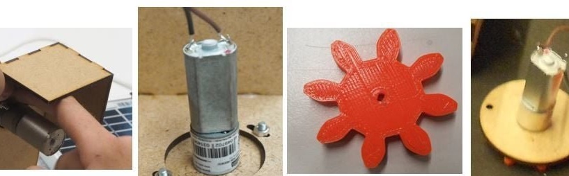
Step Six: Engine
Solder the 2-pin connecting cable to the motor. The motor will be inserted into the base plate of the heliostat. Connecting the voltage regulator to the board
Seventh step: assembly of the support part and the rotary mechanism
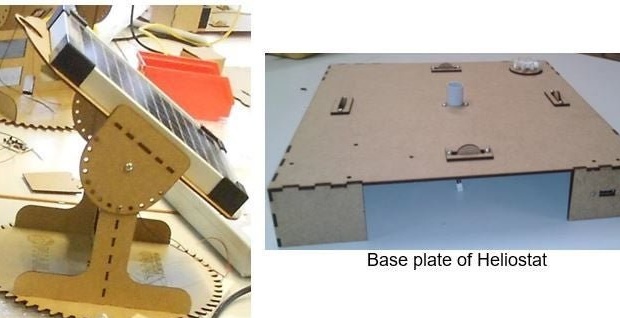
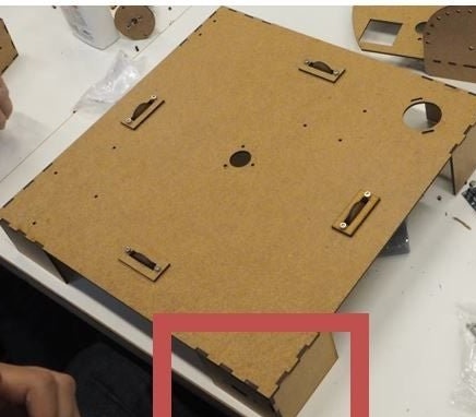
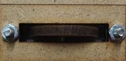
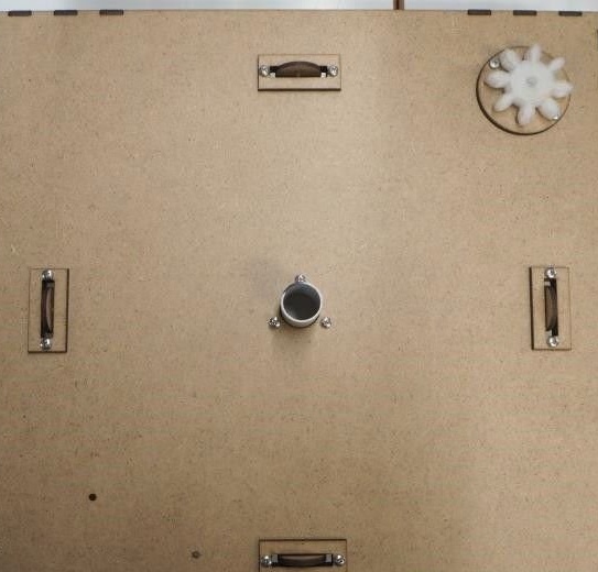
The mechanical part of the heliostat consists of a base made in the form of a box on which a rotating base plate is mounted.
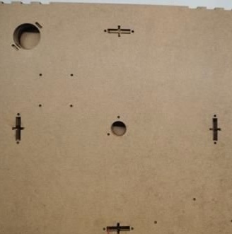

Lay the base plate in front of you and make sure that the large hole is in the upper right corner.Glue the legs in the corners of the support.
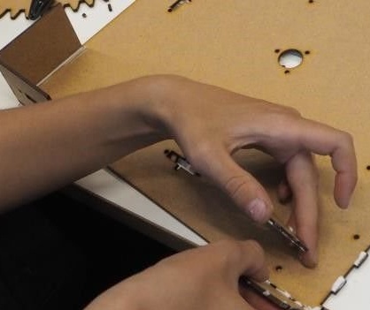
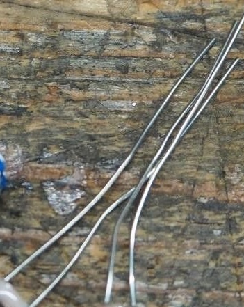
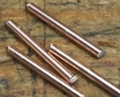
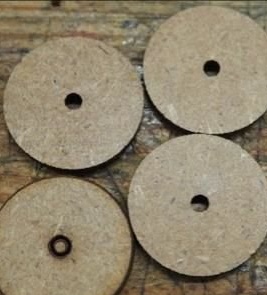
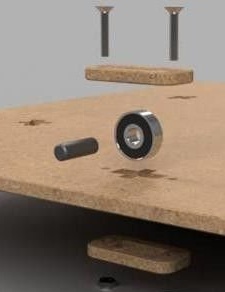
Next, you need to fix the wheels and gear on the turntable. The axles used are wire.


Then the engine is installed and fixed.
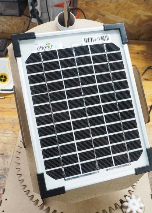
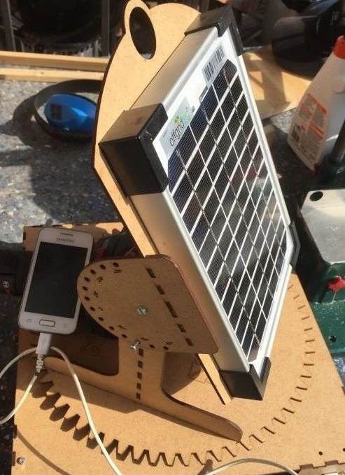
Going to mount the solar panel.
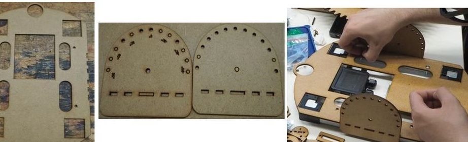
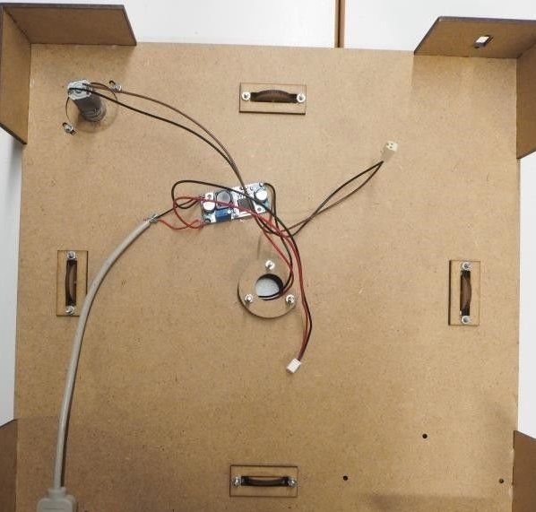
It remains to install the panel and secure the electronics from the bottom of the base. Now everything is ready and you can try to charge your mobile phone.