I want to talk about my homemade based on a fan (cooler).
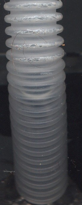
I decided to make a hood for soldering.
I wanted it to be not noisy, productive enough and at the same time the outlet pipe would be small in diameter so as not to drill huge holes in the walls.
I decided to use the fan that is used in computers.
Why? They are brushless, so little noisy, quite productive and durable.
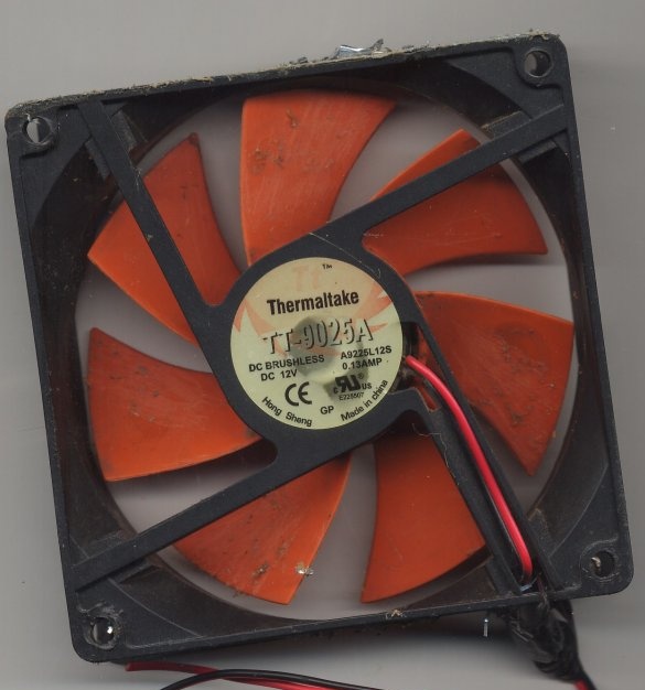
At my fingertips was this:
Thermaltake
Power 12 V, consumption 0.13 A. I was of little interest.
I needed to know its performance.
And I went online, on the fan brand TT-9025A, I found 56 CFM.
CFM is an Old English measure of water flow rate. Cubic Feet per Minute.
But, it applies now to the air flow, to the fans, for example.
I came to the conclusion that 56 CFM is enough for me for this installation, especially since this cooler blows well, I knew from the previous work with it.
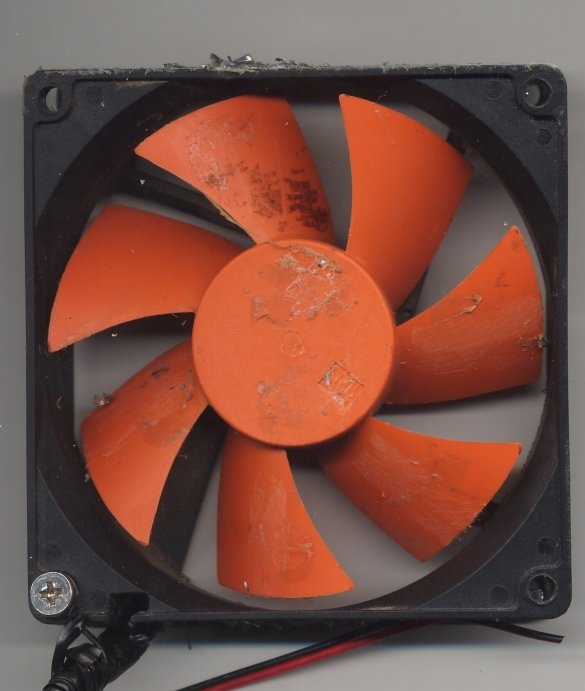
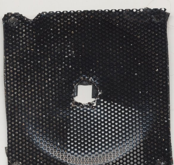
Decorative - protective lattice to him I had, I found it. The fan is powerful enough, high-speed, the impeller has seven blades and easily cuts fingers. As it turned out later, this grill helped me understand how to achieve a positive result in the manufacture of this hood.
Some base was needed to mount the components of the hood.
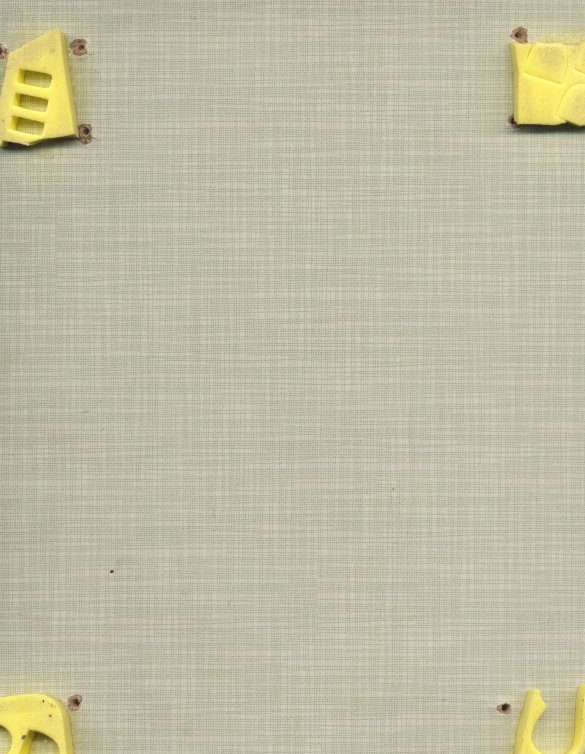
The choice fell on a rectangular plaque for of furniture. I used to collect my homework on this plate. Four glued shock absorbers from the packaging material of the Chinese laser pointer are visible.
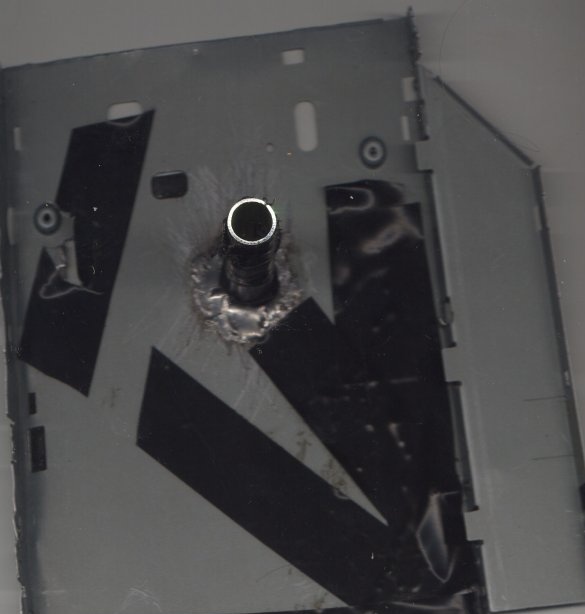
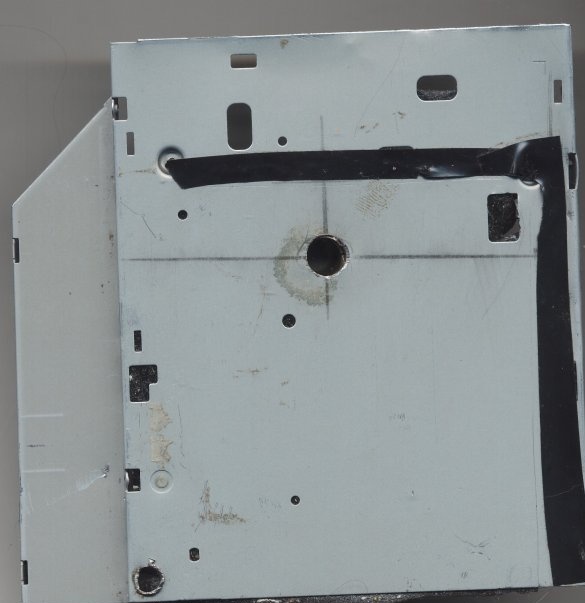
According to my idea, a tin plate and a tube with a diameter of ten millimeters were required so that they could be soldered. I saw the cover from a disassembled, outdated, CD-ROM drive and a frame dowel with a knocked-down thread.
Sharged from this the output part of the hood. Roughly cut the drive cover with scissors for metal. Straightened with pliers and a hammer. I marked holes in the piece of iron for the tube and for connecting to the fan. He screwed and drilled holes with drills of the required diameters.
I cleaned the edges of the hole for the tube and one end of the outer part from the useless frame dowel. Soldered the tube to the piece of iron. I applied the so-called solder fat. It solders steel parts well. And it does not spread, like some other active fluxes. The fact that the parts are steel, first checked with a magnet.
I soldered with two soldering irons at the same time, since it is difficult to warm the glands. He heated 80 watts with one soldering iron, and 40 watts, in fact, soldered with another. After cooling the structure, the remnants of solder grease were washed off with solvent 646. I checked the strength of the connection and if there were any gaps around the circumference of the solder.
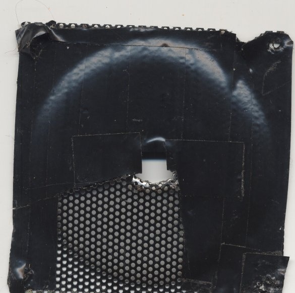
There were slots in the tube from the frame dowel (according to the principle of its operation). The drive cover also had slots and holes for various purposes. I shook it, sealed it with electrical tape.
When I was wondering how I would assemble the structure, the first thing I did was carefully examine the cooler from the sides. On one of them I found arrows showing in which direction the fan wheel rotates and where it is blowing. Accordingly, I brought the power wire to the side and additionally secured it with a clamp.
After that, he laid out all the components in series, according to his idea of creating this hood. Then he connected them with screws. Self-tapping screws had to be selected different in length and thread. Screwed and twisted them more than once.
After that, using small metal corners and wood screws, I fixed the entire structure to the base.
The most exciting moment has come. Test the installation in action.
According to the polarity of the cooler wires (as usual, plus - red), I connected my laboratory power supply to it, after setting the voltage to 12 V.
The fan began to spin. First of all, I brought a sheet of A4 paper to the decorative - protective lattice. He was attracted to the grate. So, everything is assembled correctly.
After that, I brought the sheet to the output tube. The sheet declined. That's right too. But, he deviated very weakly. I do not need such a hood.
Then I began to conjure with holes and crevices. It:
Slots in the joints of the components of the installation, holes in the decorative-protective grate. I reliably glued everything except the grill with high-quality electrical tape.
Strange, but the hood began to work worse. Then I began to peel, sometimes cut off the electrical tape.
The results changed randomly.
I began to come to a standstill.
And, suddenly, I remembered the Bernuli law!
Which says that in liquids and gases, with increasing flow velocity, its pressure decreases. And vice versa.
I realized that I need to make a smooth adjustment in some way, and by glueing and unsticking the electrical tape I will achieve nothing.
In the center of the decorative and protective grille, I drilled a hole commensurate in diameter with the inner diameter of the outlet tube.
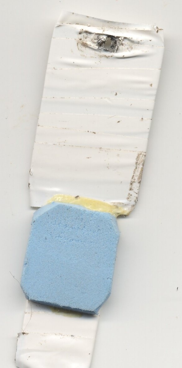
And he made a special, adjustable damper or gate valve, and you can call it that.
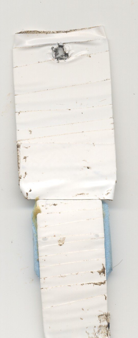
I took a fairly elastic plate from some alloy, from a disassembled technique.
I cut the desired shape with scissors for metal. At one end of the plate, I drilled a hole for mounting. I wrapped the plate with electrical tape and glued a pad of elastic material that caught my eye.
For a long time I bent the plate in every way, trying to ensure that the damper overlapped a large hole in the center of the decorative - protective grille to the necessary degree. In this case, the damper must not spontaneously change its position. For this, we need an elastic plate and pad.
As a result, it turned out. The damper made it possible to very accurately regulate the ratio of incoming and outgoing air flows.
Moreover, I managed the incredible! Make the fan designed strictly for blowing, without changing the direction of rotation of the impeller, without moving it in the casing, work on suction!
The blades spun in the same direction, and the cooler sucked in air!
I decided to make sure that this is not a dream.
He put a fingertip on the output tube and tightly wrapped it with electrical tape. In one position of the damper, the fingertip inflated, that is, overpressure was created in it, and in the other position of the damper it contracted - in it a vacuum was created. When the fan power was turned off, the fingertip took its usual form (the pressure in it equalized with atmospheric pressure). At a certain position of the valve, with the fan running, there was no air movement, which does not contradict the laws of science.
I have a video of this test. I am enclosing screenshots from this video with my explanations:
Rear view of the installation
A fingertip is put on the output tube
High pressure inside the fingertip

Inside the fingertip
Flap adjustment process
With a sharp change in the position of the valve, due to changes in the speed and pressure of the air flow, there was a short-term, peculiar sound, similar to smacking. When working in normal mode for hood or suction, the fan was almost inaudible, even when I was nearby.
Now I will show a simplified installation diagram.
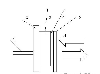
1 - output tube, a flexible hose of small diameter is connected to it, which is displayed outside the premises.
2 - plate
3 - fan (cooler)
4 - decorative - protective lattice
5 - adjustable shutter
The arrows indicate that the air can move in both directions or not move at all (depending on the position of the damper).
After some time, I decided to improve this system. Its dimensions will decrease, and the noise level will not change, the power will increase. I know how to achieve this.
I hope you were interested in familiarizing myself with my homemade product and, based on the foregoing, make something like that.
Sincerely, author.

