
In this article, the author of the YouTube channel "NightHawkInLight" will tell you how he made the levitator.
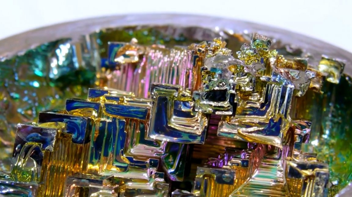
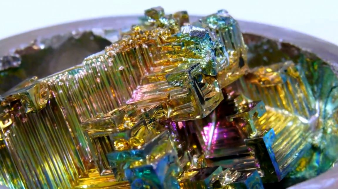
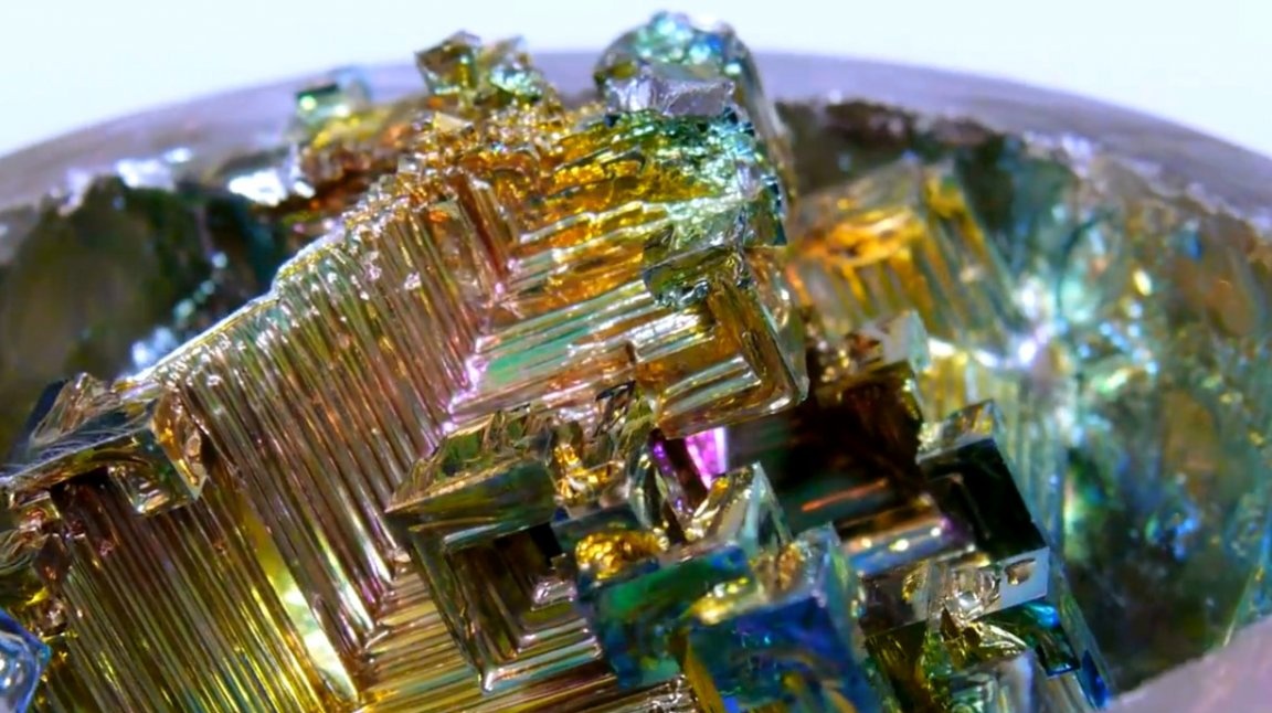
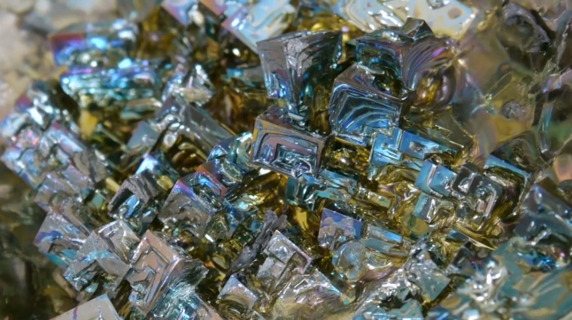
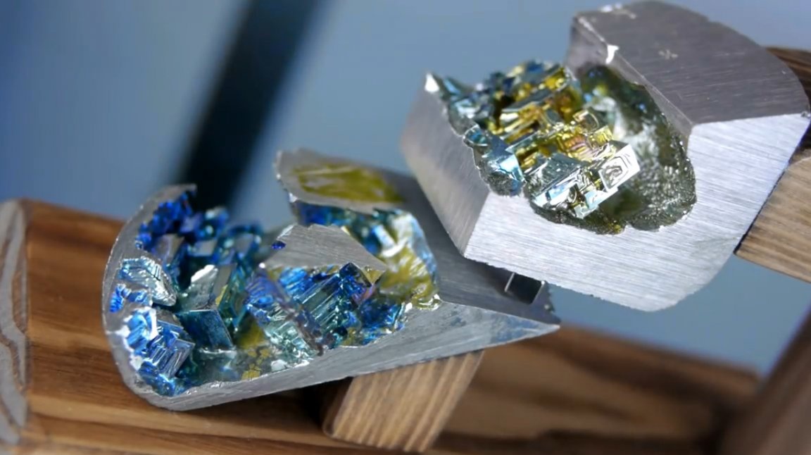
Perhaps the reader will be interested to know that such a metal as bismuth has a number of completely amazing properties. Firstly, it melts easily at fairly low temperatures (271.4 ° C); secondly, it is capable of forming crystal formations of unprecedented beauty. But the author put a completely different quality into the basis of this project ...
The fact is that bismuth is an excellent diamagnet. It forms its own magnetic fields that counteract any other field coming from outside. Given this feature of bismuth, it is possible to use this property of bismuth for practical purposes to react to the approach of a magnet in an opposite way to iron, namely, by repelling it.
Materials
—
—
—
- copper pipe
- Hardwood
- Two-component epoxy resin
- Sandpaper.
Instruments, used by the author.
- Gas stove
- Hacksaw
- Drilling machine.
Manufacturing process.
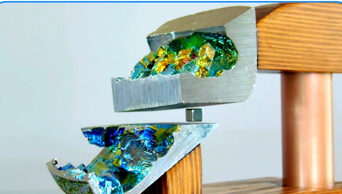
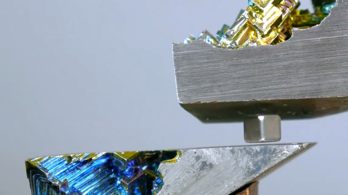
So, the author intends to use the described property of this metal to create a so-called static "pocket" of two opposing magnetic fields. Being in such a “pocket”, a small magnet is able to successfully levitate between two magnetic poles.
In practice, it is very difficult to find a position of the magnet in which it will hang in the intermediate space. It doesn’t matter how accurate and accurate you are, the magnet will either break down or stick to the top magnet.

The diamagnetic levitator, which the author is going to construct, will take the repulsive force of two diamagnets as a basis.
Bismuth will be located on both sides at the point of balance, preventing the levitating magnet from moving too far away from the central position. Each of the ingots will neutralize the attractive force of the other, located opposite the magnet, bringing to an equilibrium state an object located between the two poles.
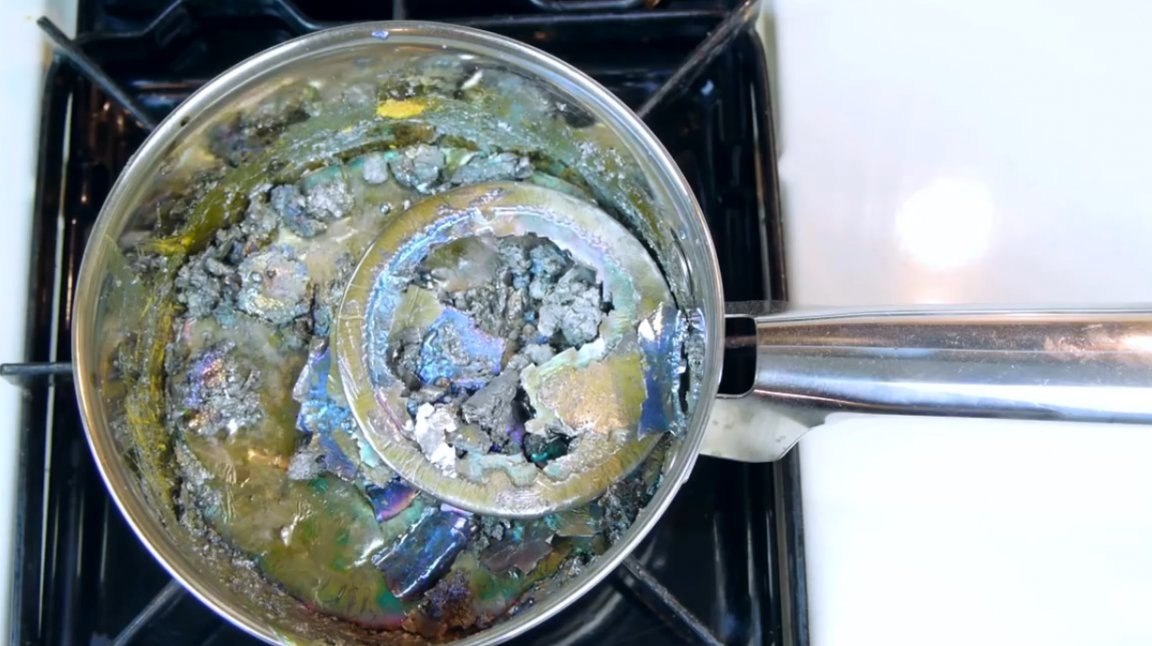
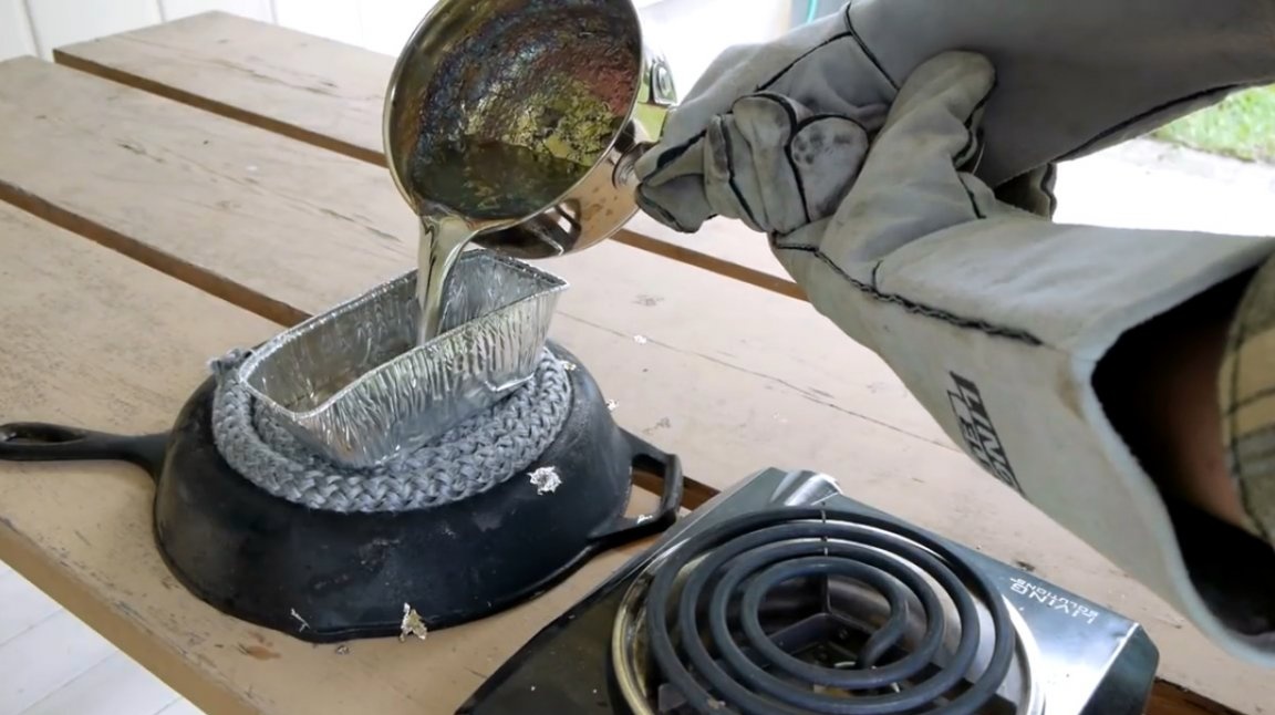
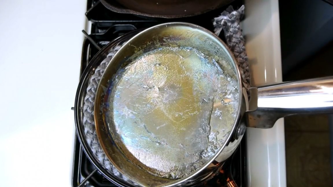
First, the author melts in a steel tank his old bismuth fragments.
And then he pours the resulting thick liquid into a small ceramic bowl.But first, he warms up the ceramics a bit so that it does not burst when they start pouring hot metal into it.
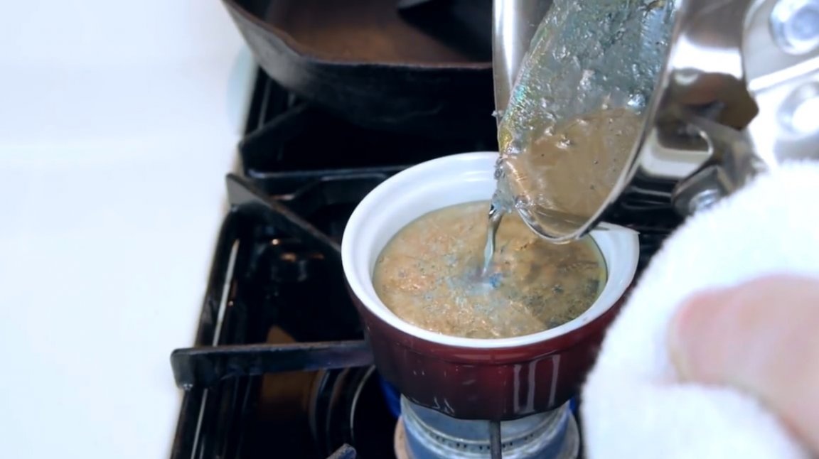
The author still does not recommend casting metal on his own in this way.
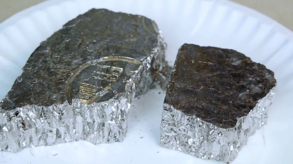
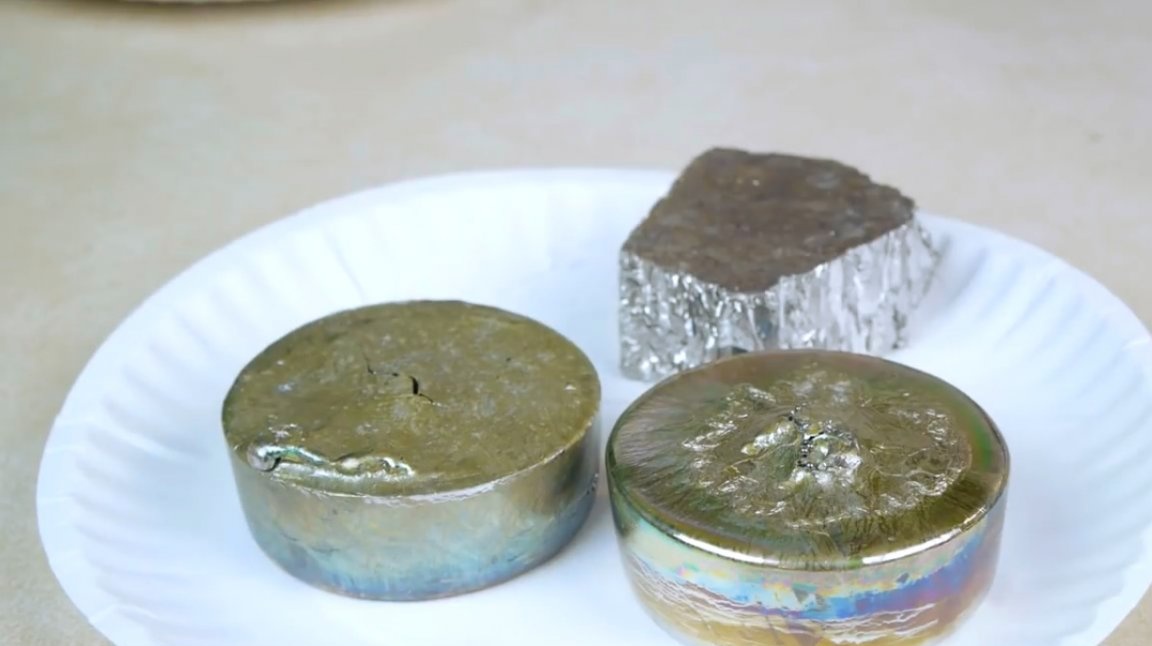
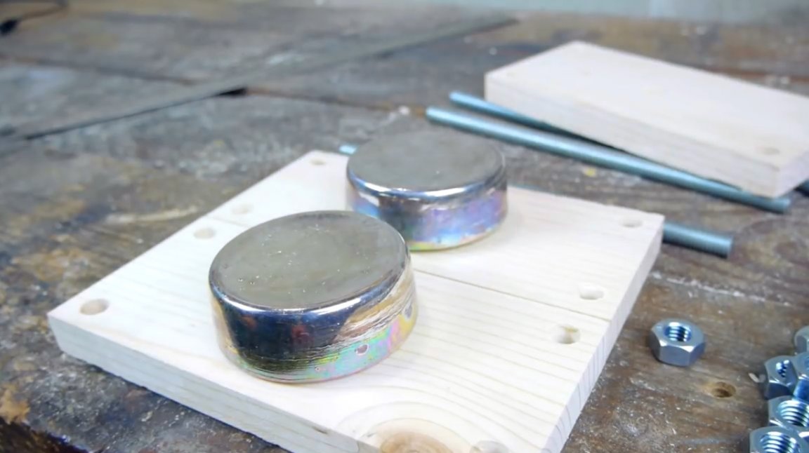
These are the ingots.
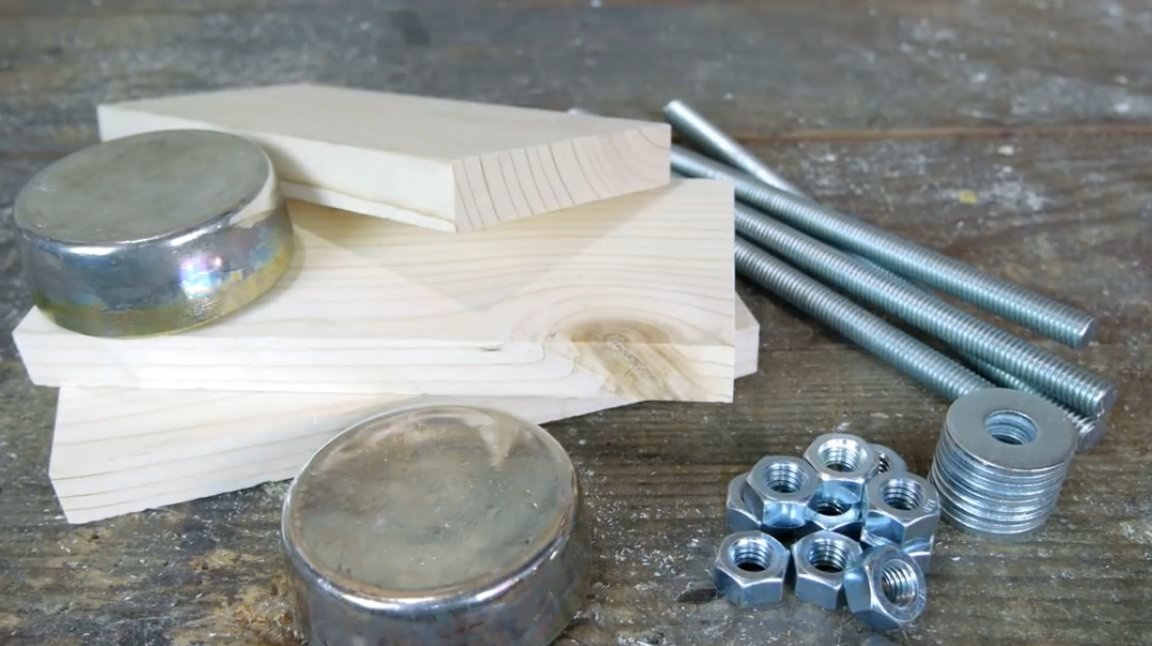
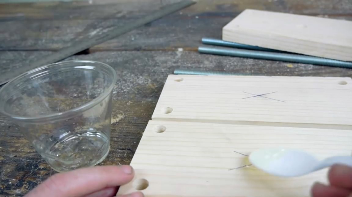
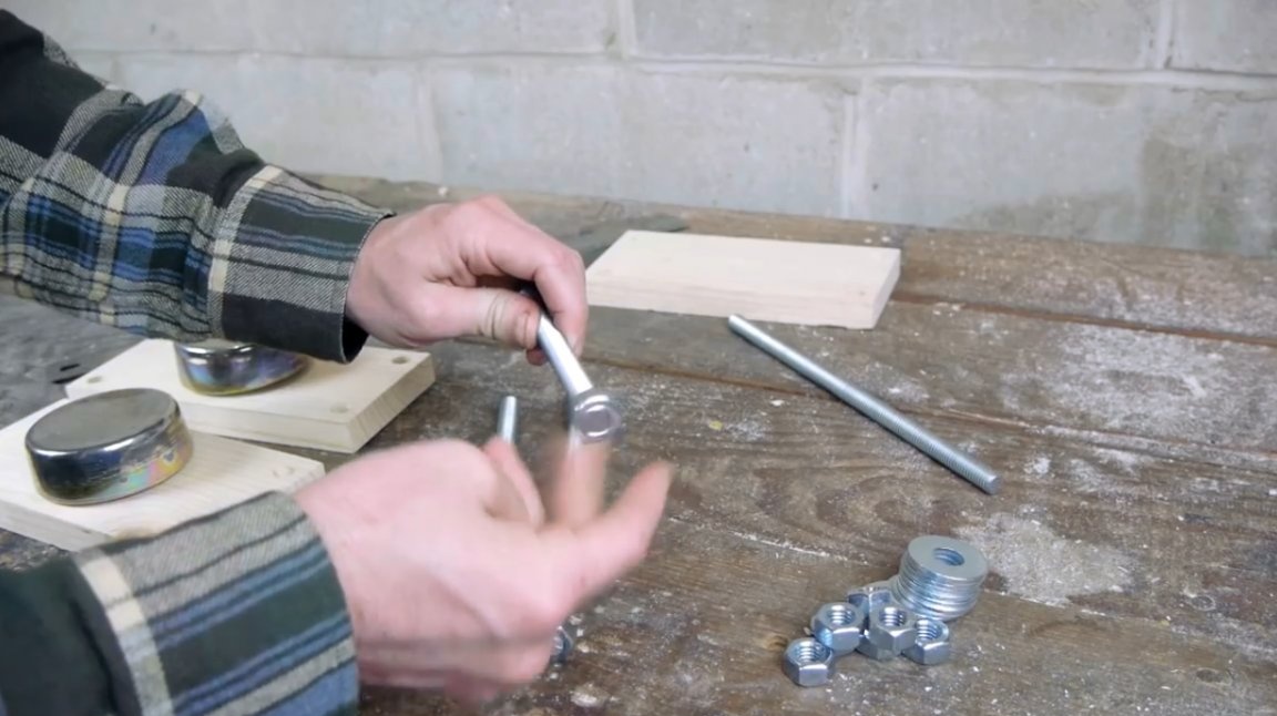
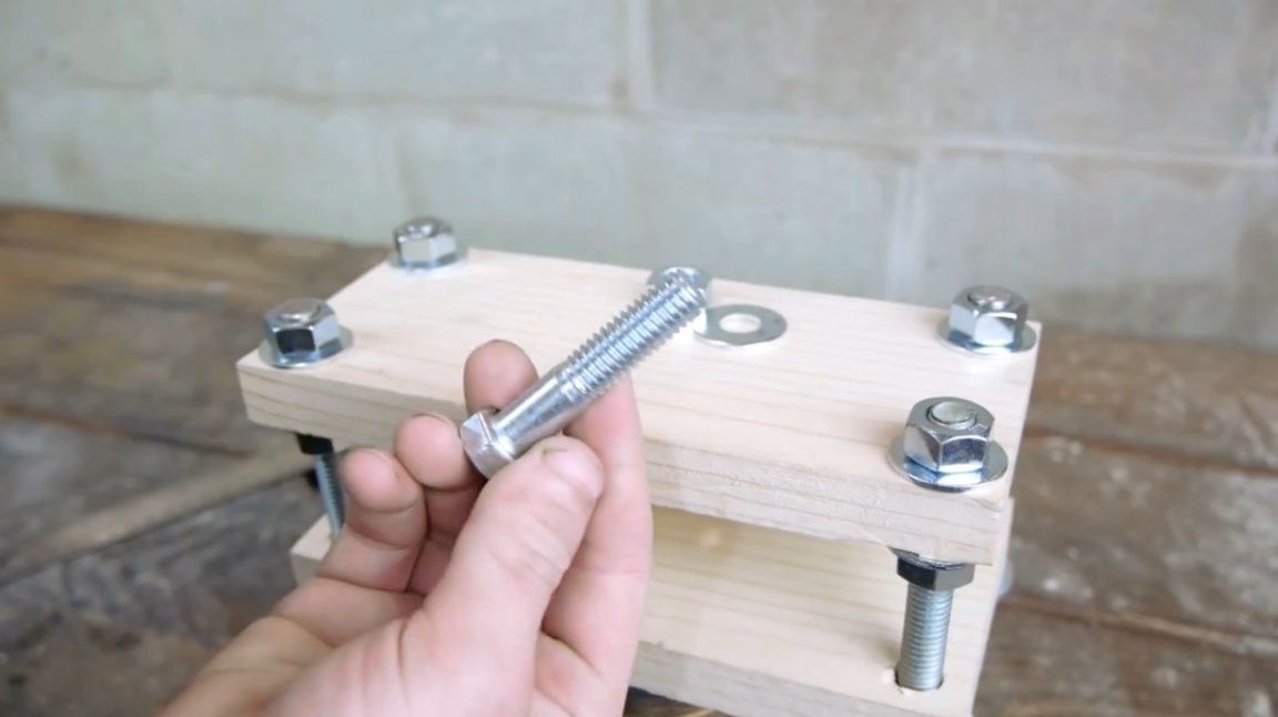
Now the author proceeds to manufacture the framework of the future design, in which the magnet will levitate. For her, the master prepares wooden planks, steel studs, a set of nuts and washers. Carving on the rods will allow you to adjust the design to the desired height when the author begins to calculate the very middle position of the magnet, in which he cannot "stick" to any of the poles.
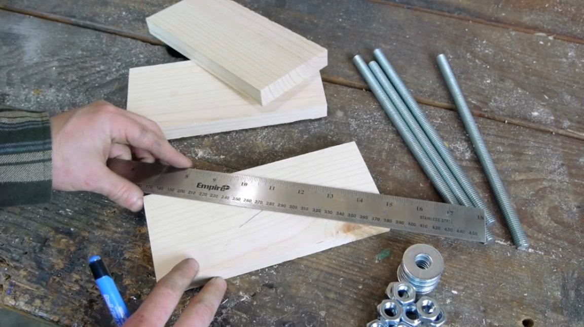
On each bar, he marks the center, and also puts marks in those places where corner holes will be drilled.
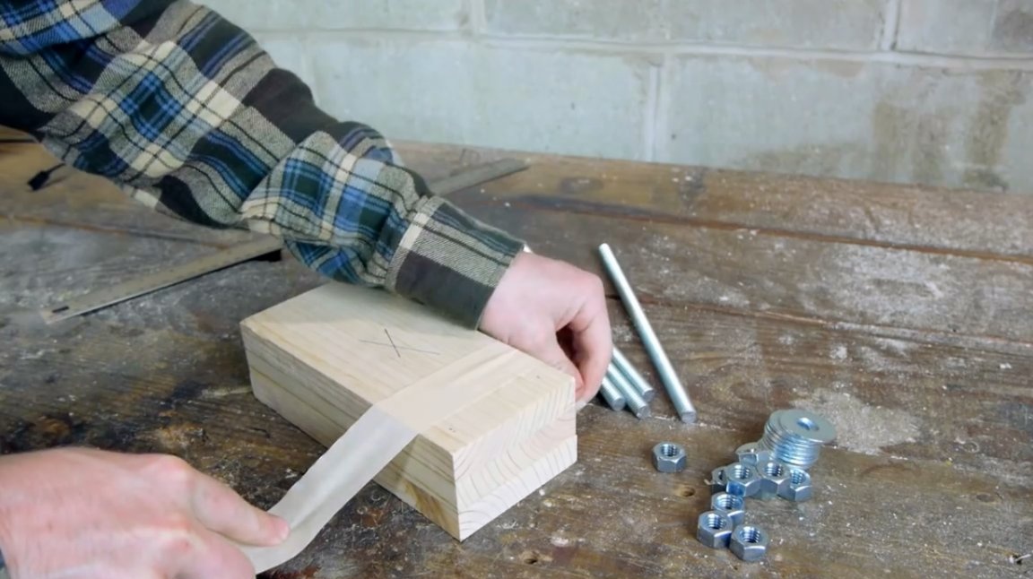
Then the master puts all three planks together and pulls them with masking tape.
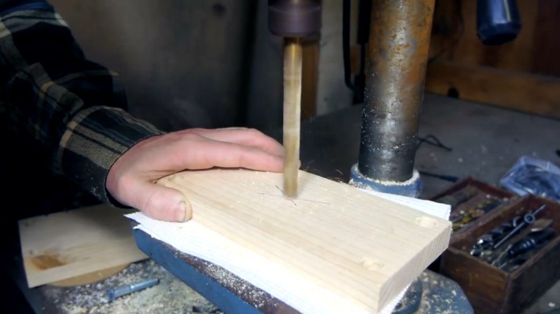
He drills them in a single block so that there is no displacement of the holes.
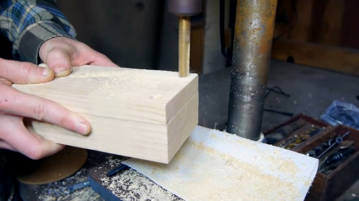
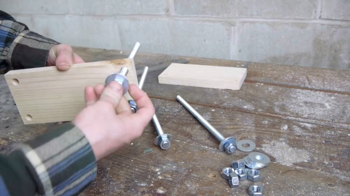
In one of the three planks, a central hole is still drilled. This is the topmost bracket on which the adjusting bolt holding the lifting magnet will be mounted.
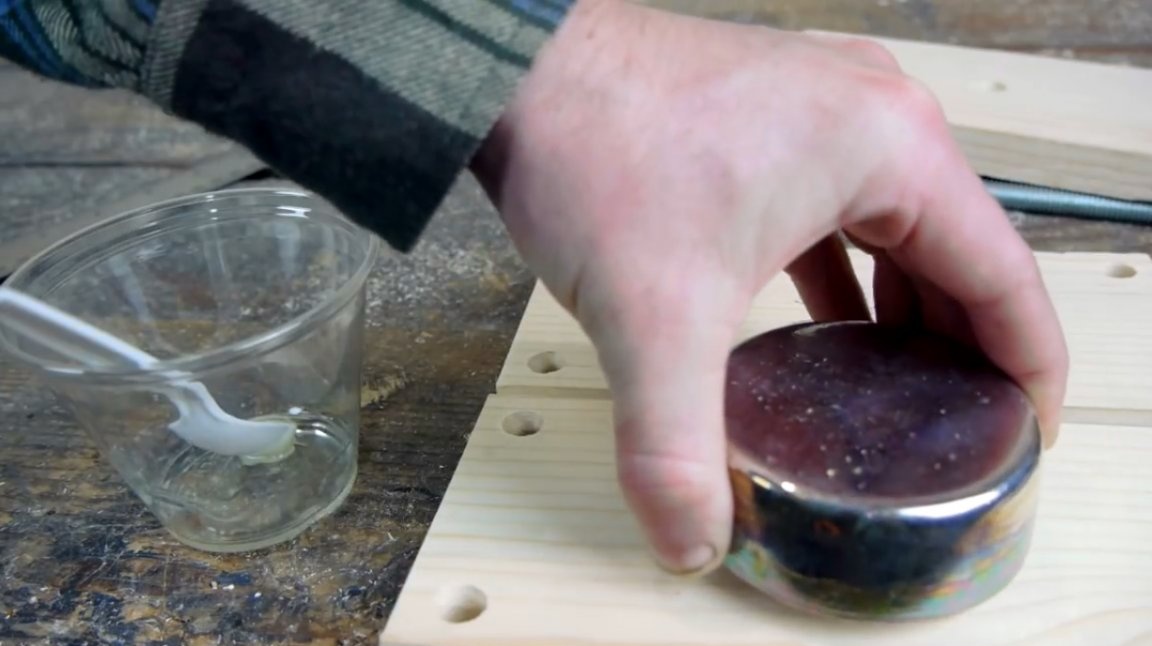
Ingots are attached to two other planks that do not have openings in the middle. They are glued to epoxy.
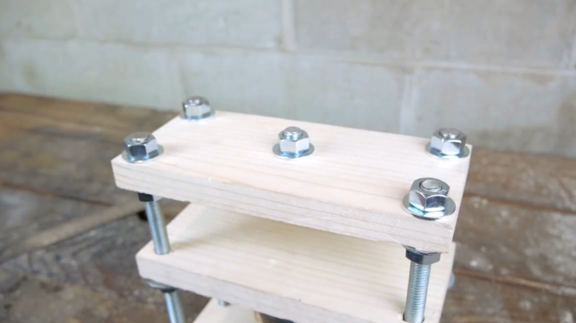
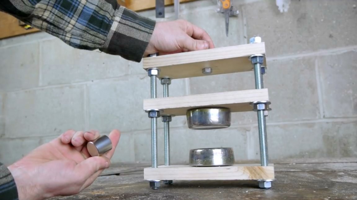
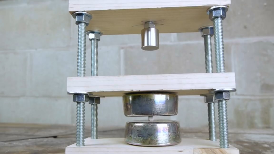
The whole structure is built on the basis of metal rods. With the help of nuts and washers, each crossbar is set to the desired level.
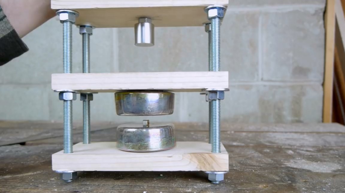
Two metal ingots are located opposite each other, in the center.
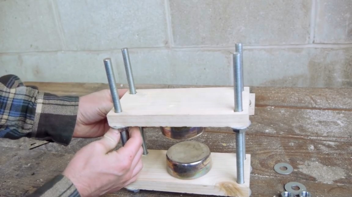
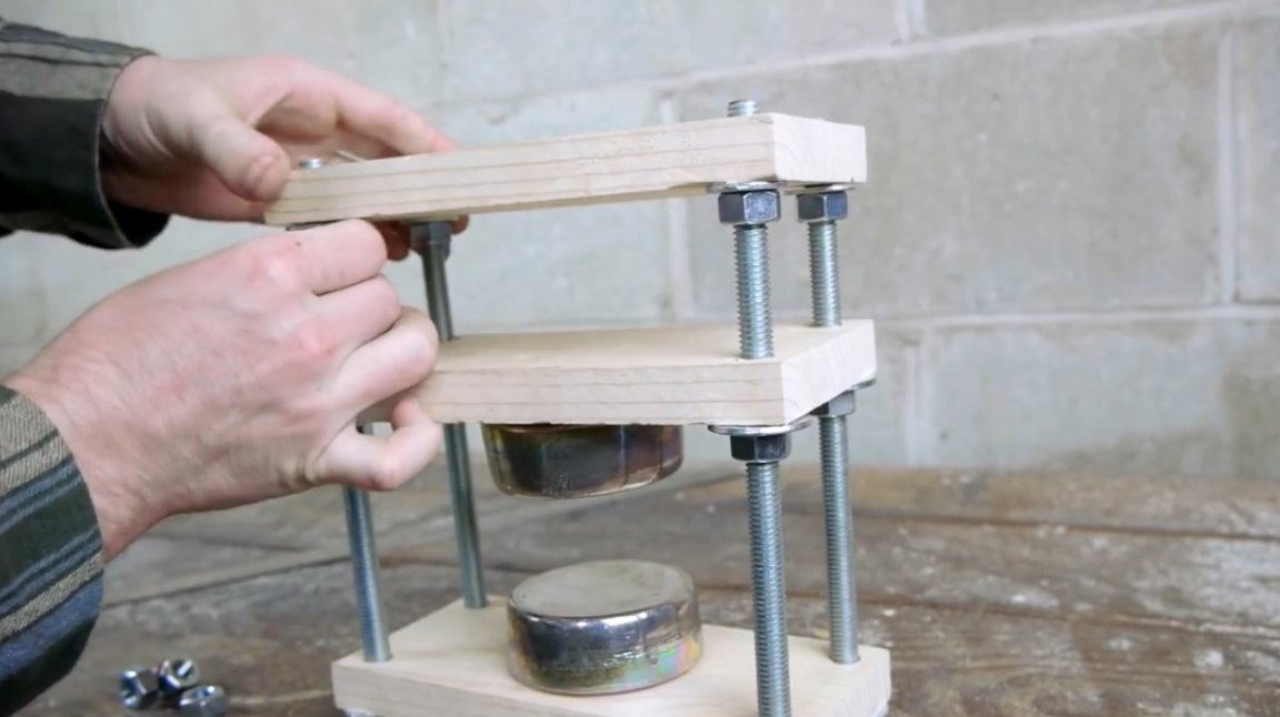
The upper crossbar is specifically designed for attaching a lifting magnet. The latter is magnetized to a bolt passed through a central hole and secured with a nut. The nut can be released if necessary, or, on the contrary, can be pulled. The magnet is located on the underside of the bar.
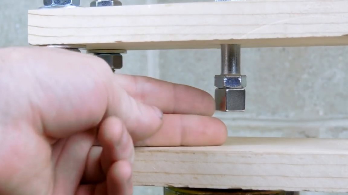
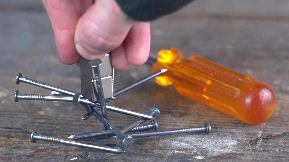
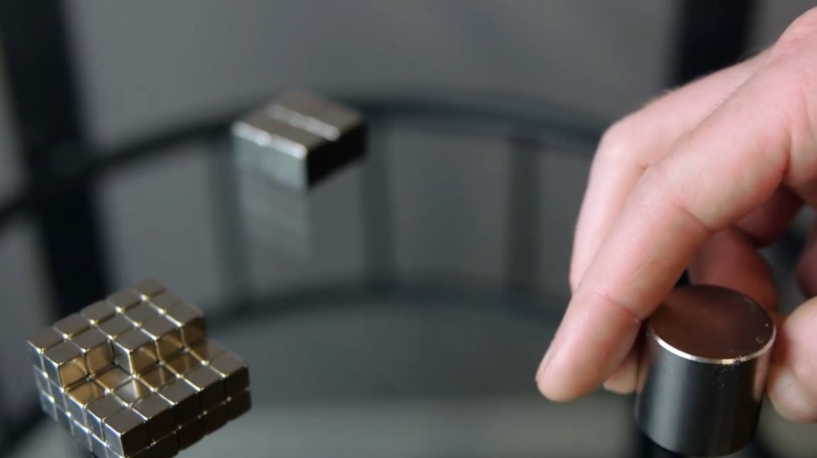
Levitator is ready. It remains only to configure it. The author has at his disposal many neodymium magnets of various sizes. It remains to be determined how many and what size of magnets will be needed in order to balance the magnetic fields.
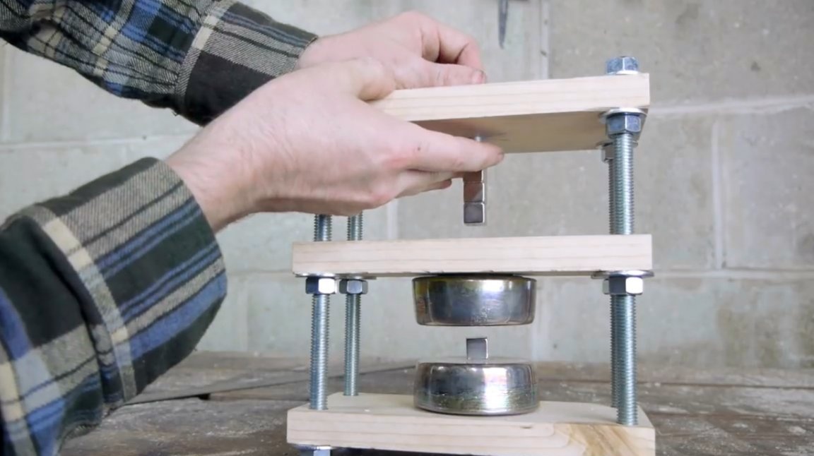
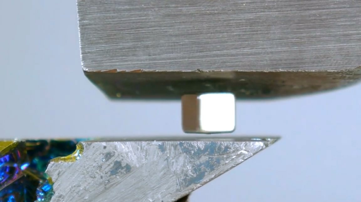
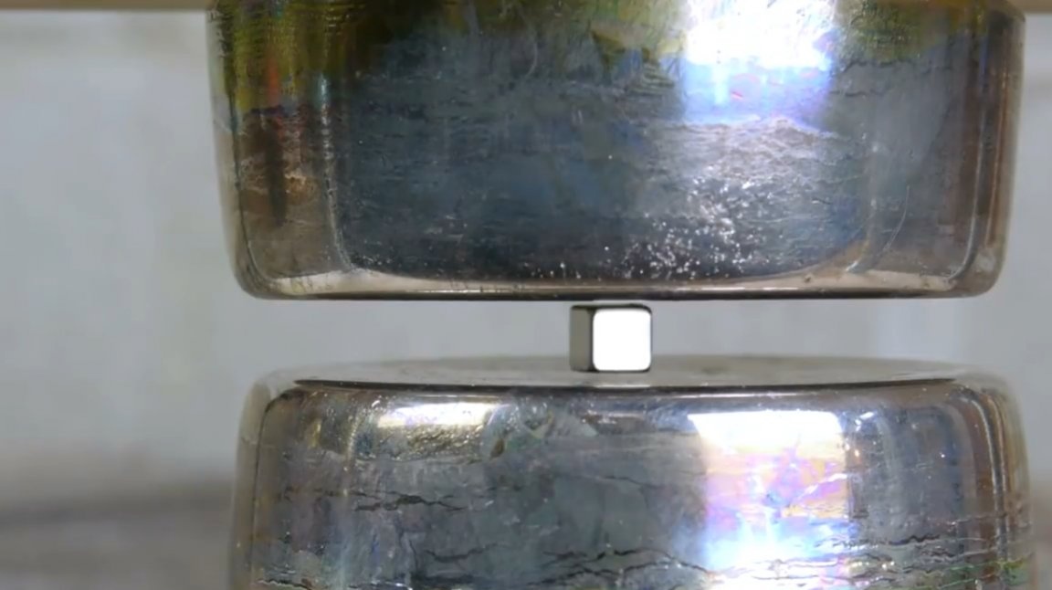
The largest combination was the largest inch magnet paired with a small 1/8 inch cubic magnet.
The most difficult moment was to expose all the structural elements in such a way as to achieve stable levitation of the “experimental” magnet.
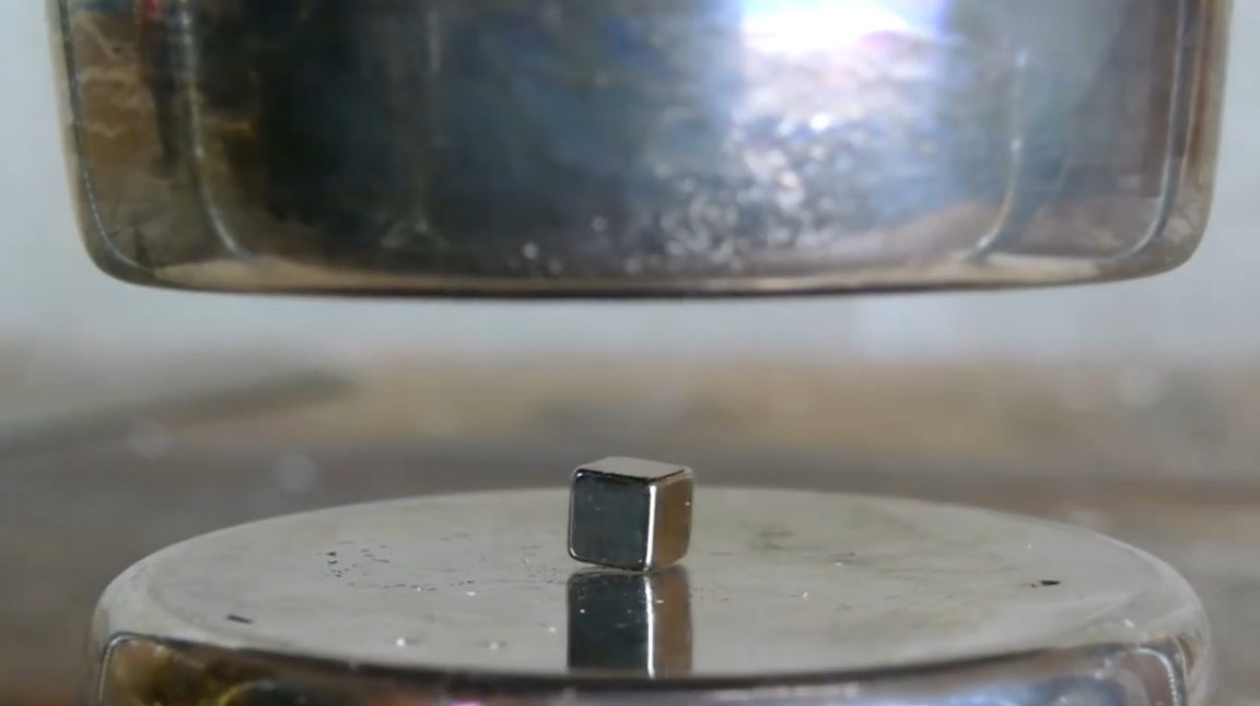
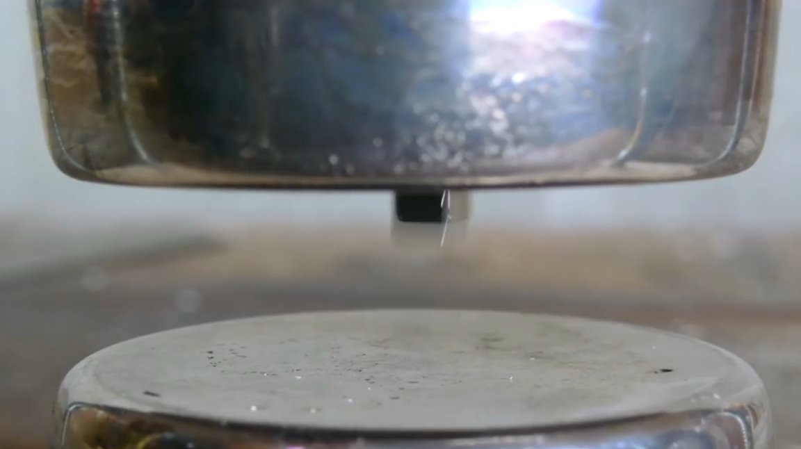
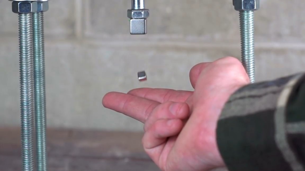
And finally, the long-awaited effect - the magnet hovers! If you leave this installation as it is, the magnet can remain in such a suspended state for at least 100 years before you need to reconfigure the structure again due to losses in the strength of the magnetic field.
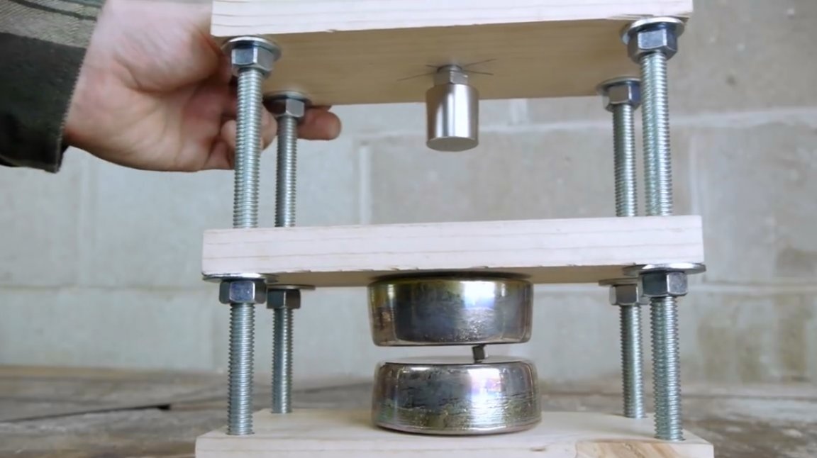
Even if you swing the installation from side to side, the magnet continues to soar!
Having convinced in practice of the possibility of creating such a levitator, the author decides to create a second, more refined design design.
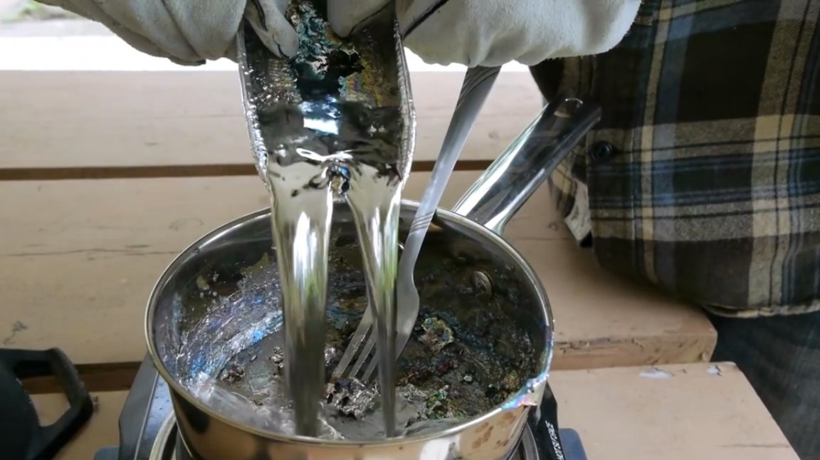
To do this, he decides to re-melt the ingots. As we remember, there are traces of epoxy on them, which can give caustic fumes.
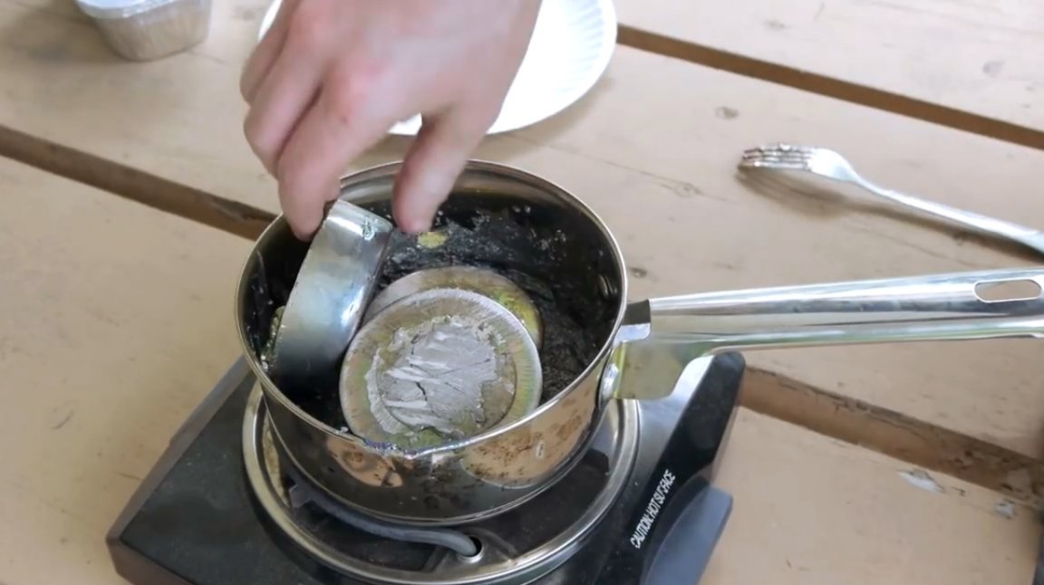
As soon as bismuth melted, the resin surfaced. It turned out to be quite simple to remove with a fork.
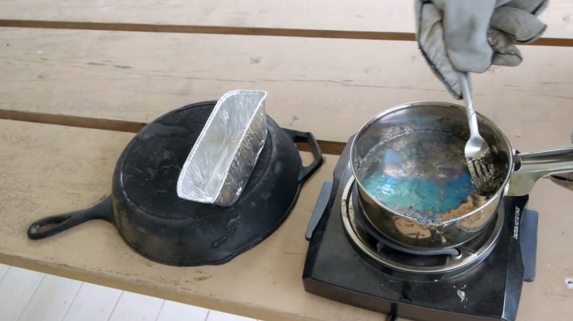
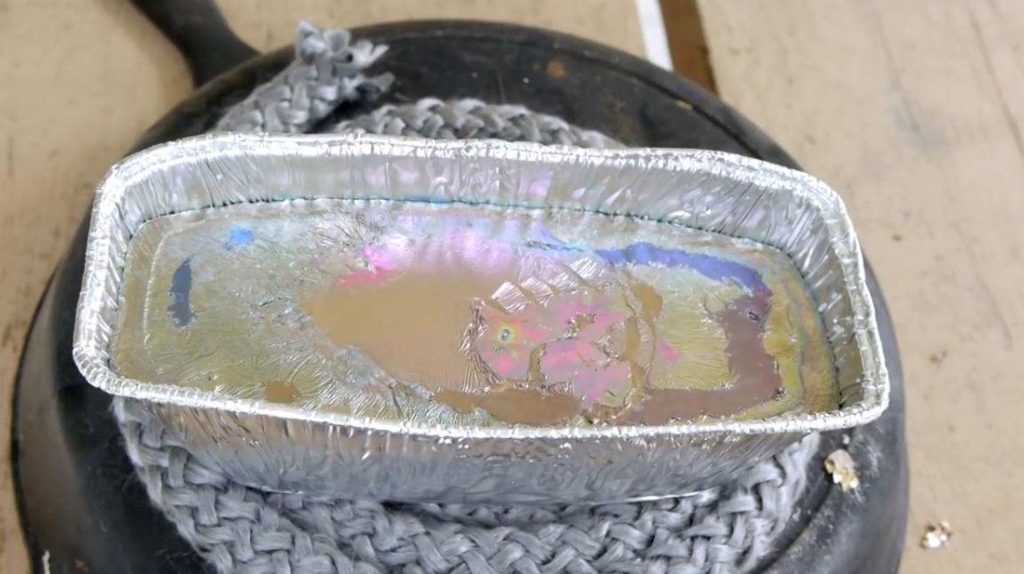
Then the author pours bismuth into an aluminum container, which, according to the author’s idea, has just the right shape for future design.
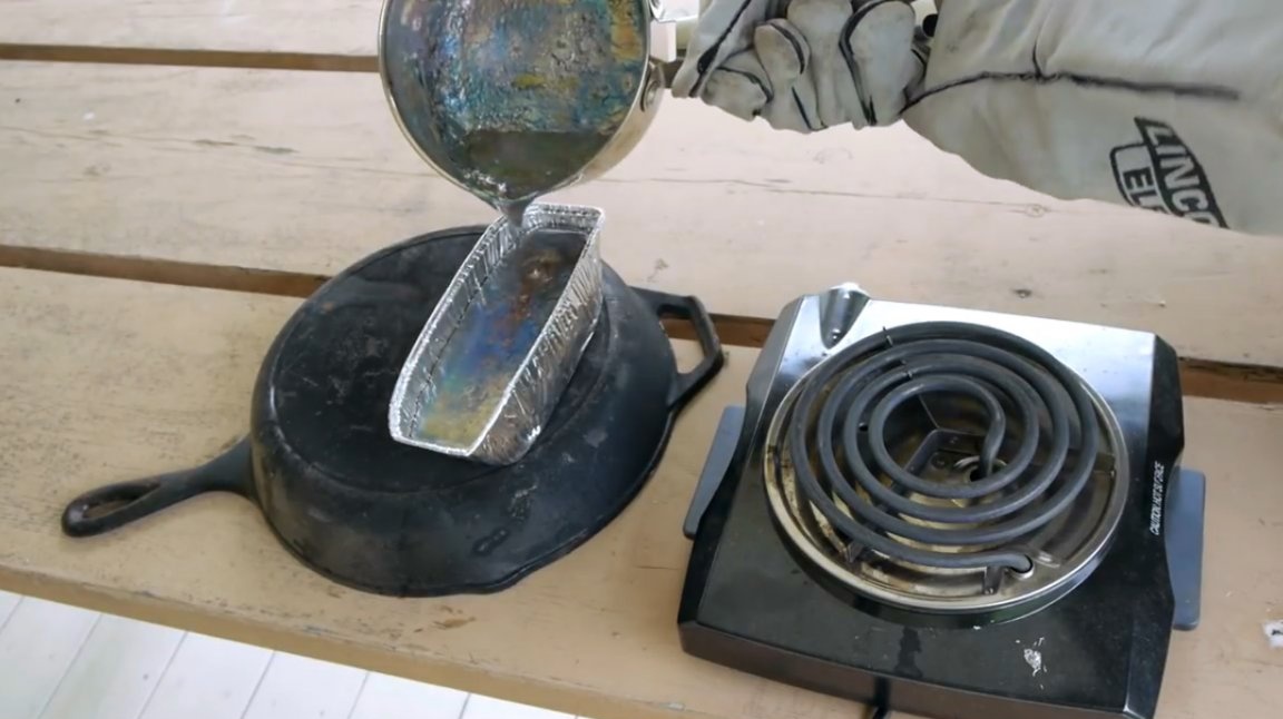
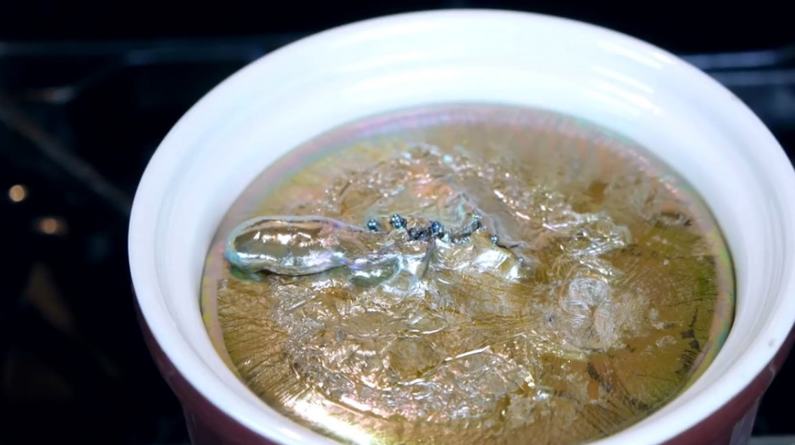
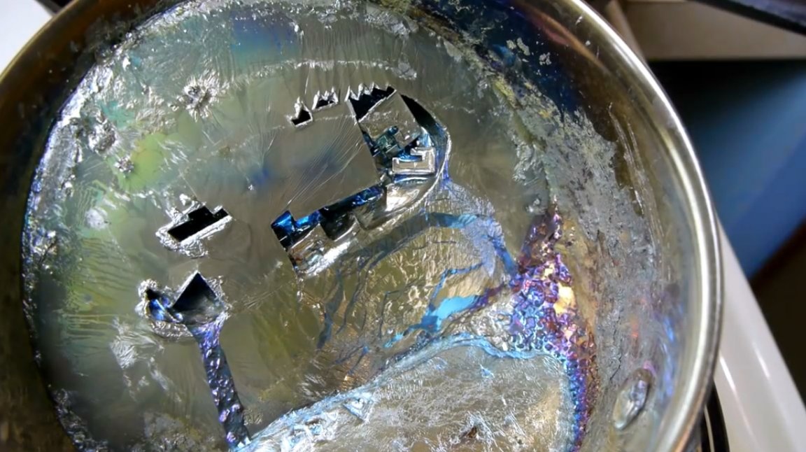
To expose the obtained crystals, at some point, liquid bismuth must be drained from the center of the tank.
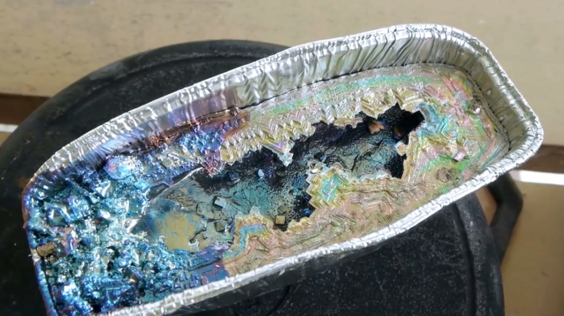
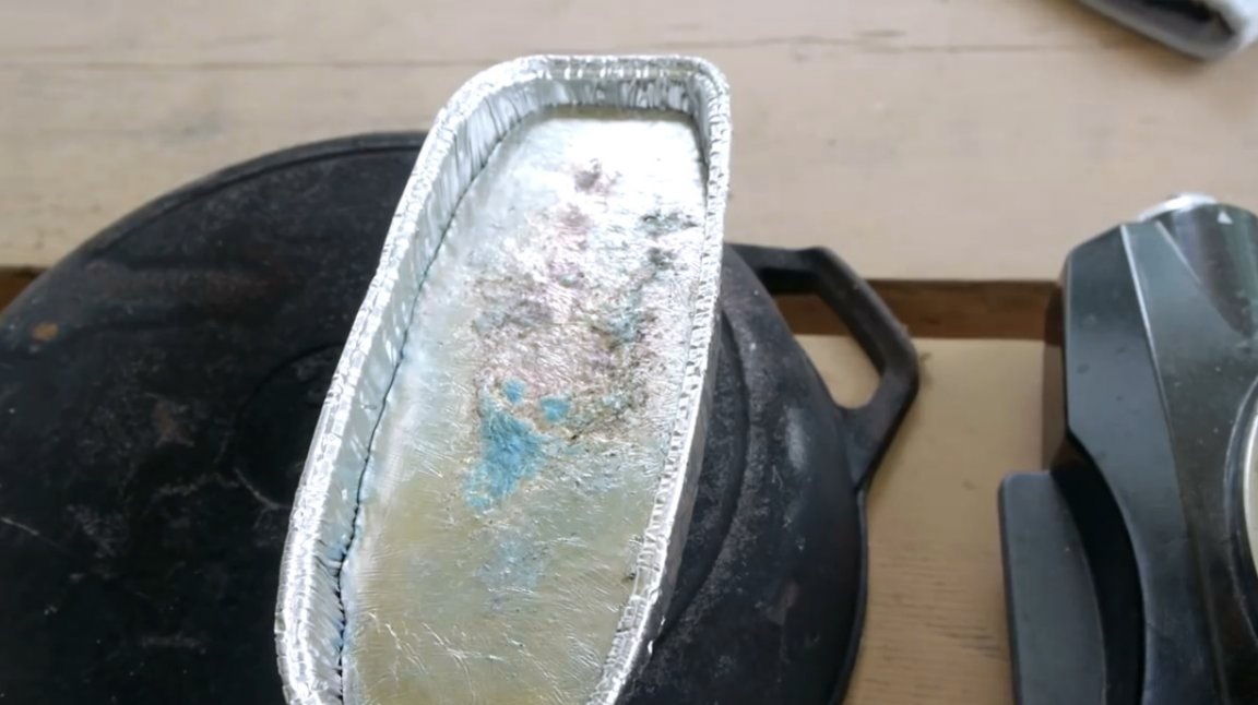
However, due to the fact that bismuth began to cool too quickly from the bottom in a new tank, crystals of an irregular and spectacular shape began to form.
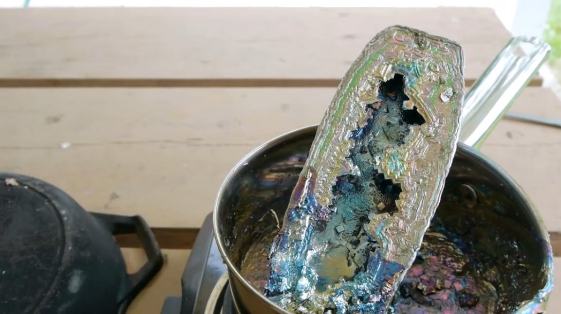
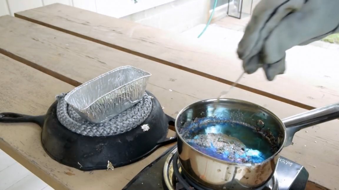
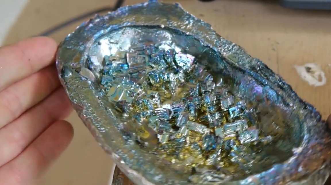
He has to repeat the experiment, having previously placed a fiberglass stand under the mold, which somewhat slowed down the metal cooling process.
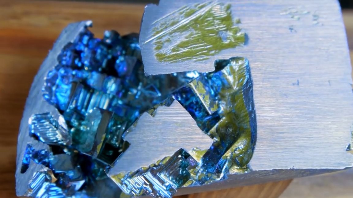
These crystals are much more interesting.
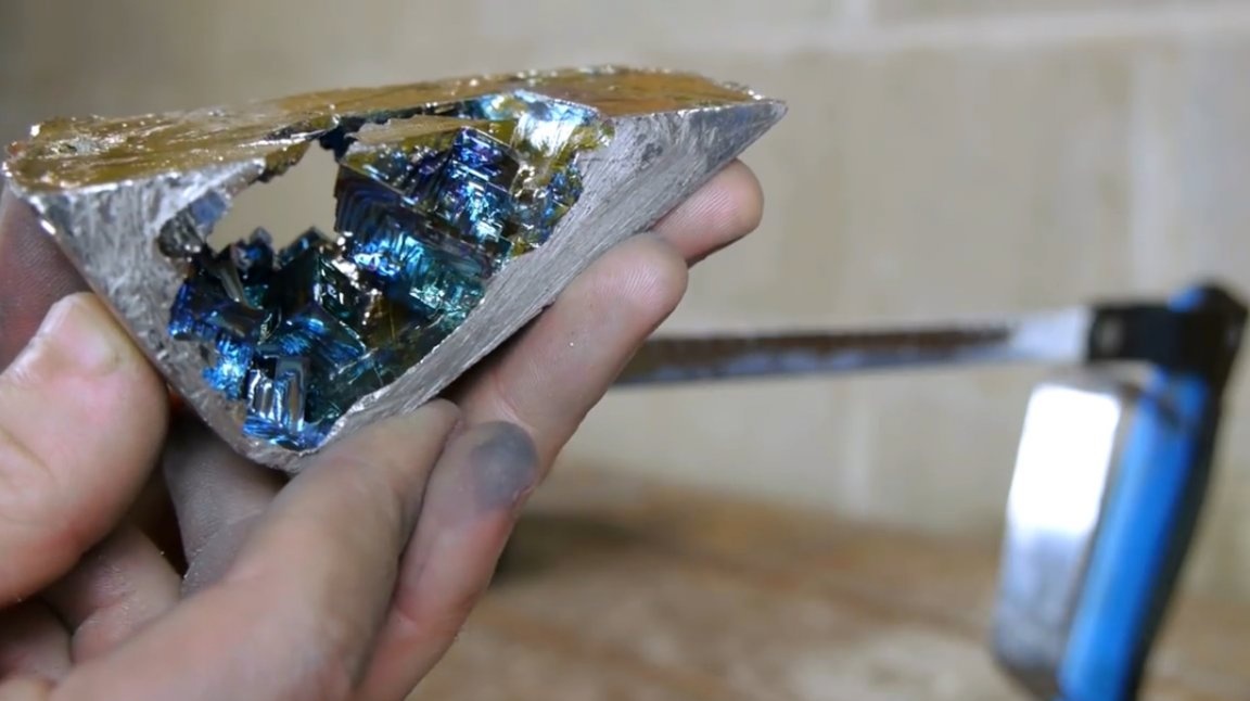
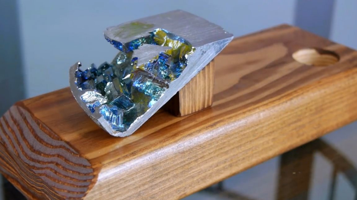
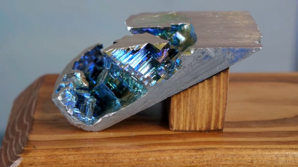
Then the author decides to use the melting ladle himself as a crucible. He also places it on a fiberglass stand and tilts it slightly. And gets a wonderful result!
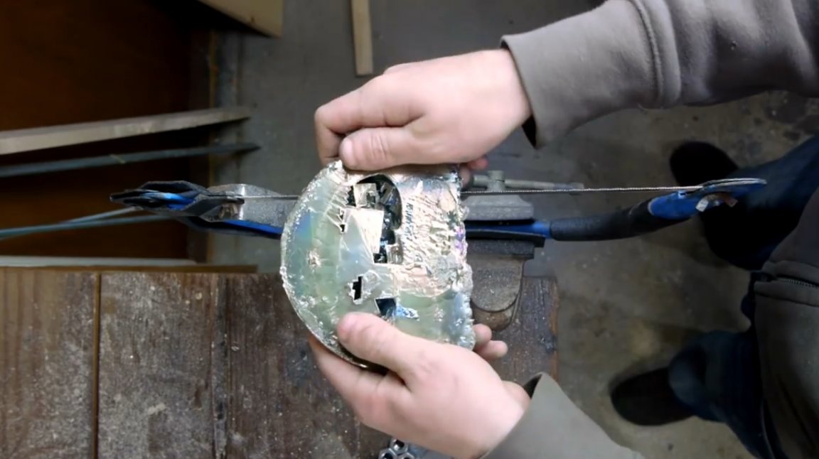
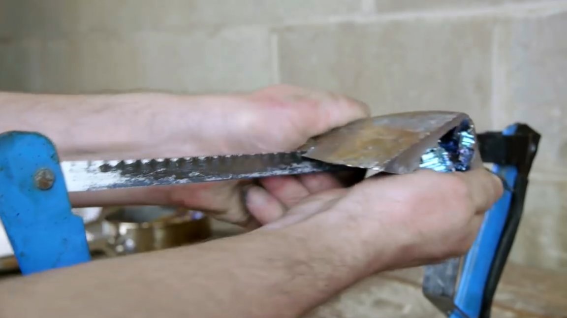
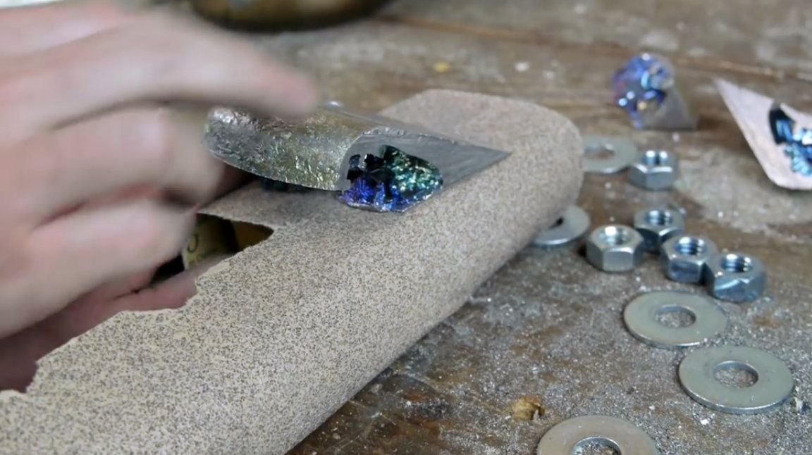
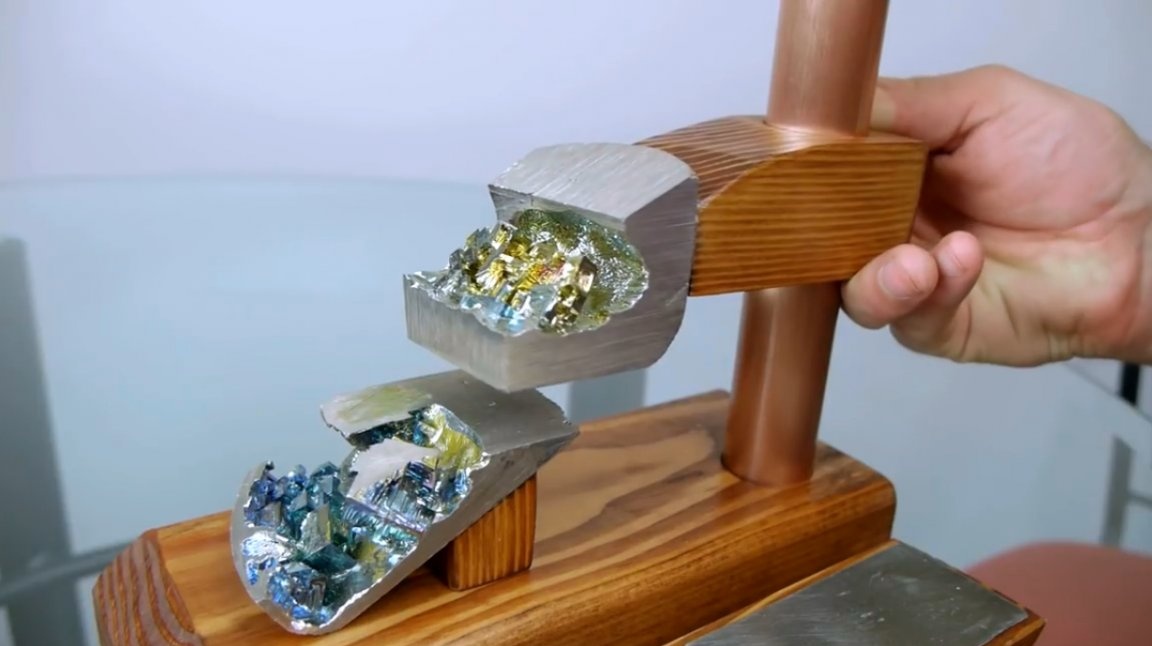
The master cuts the ingot and looks inside ...
Using sanding on sandpaper, the author managed to achieve even, smooth edges of the hardened material. These will be the main plates.
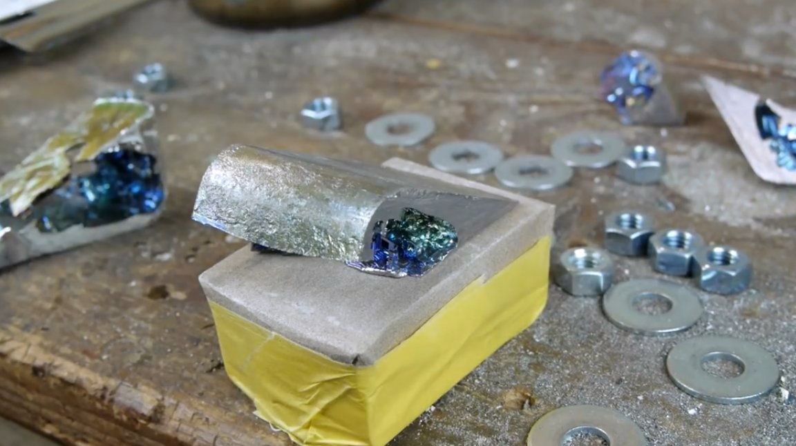
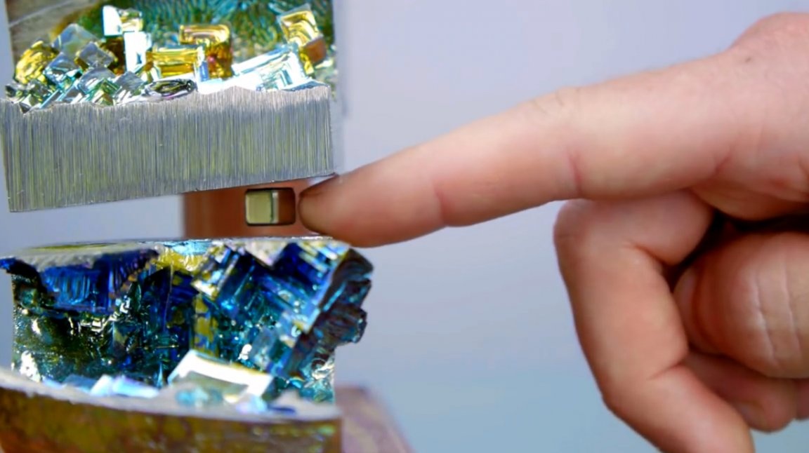
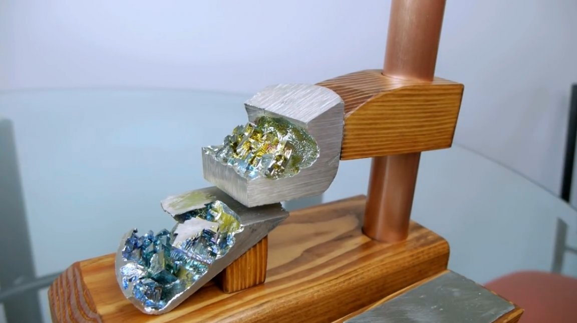
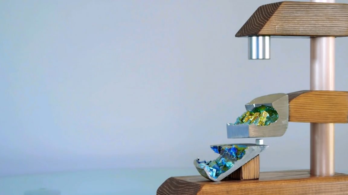
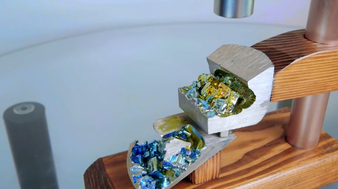
Here are all the elements of the latest levitator model.
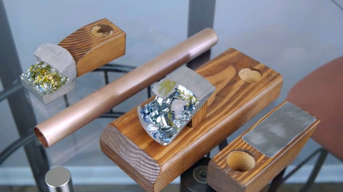
Wooden base to which the bottom diamagnetic panel is attached.
But all system tuning will be done due to the movable top panel and the panel with a lifting magnet. Inch copper tube will be the rack of the upper panels.
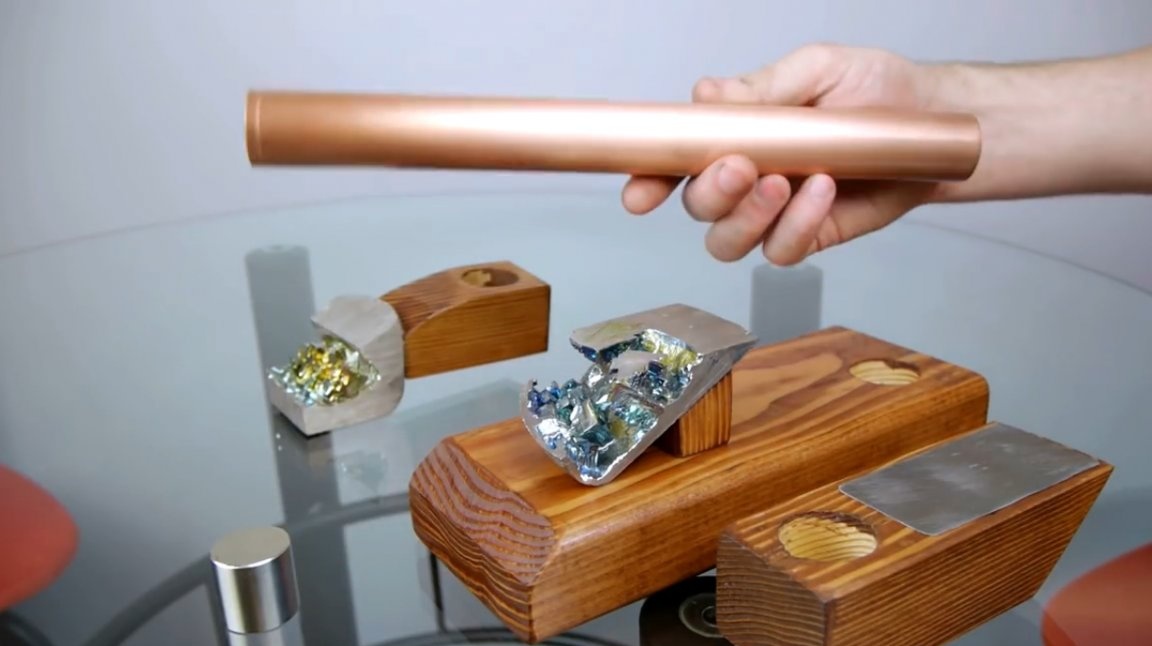
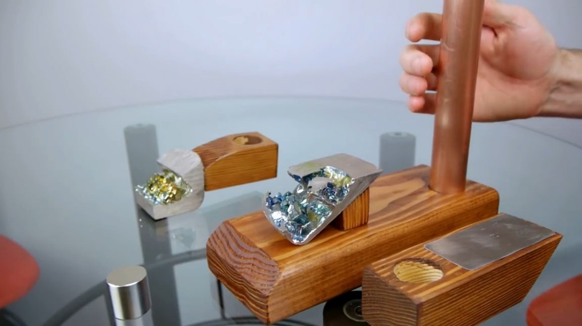
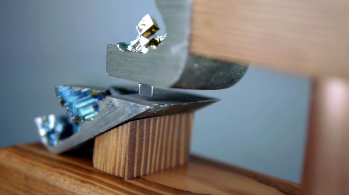
The bismuth crystal tile is glued to the wood panel with a hole in the center. With this hole she is put on the pipe.
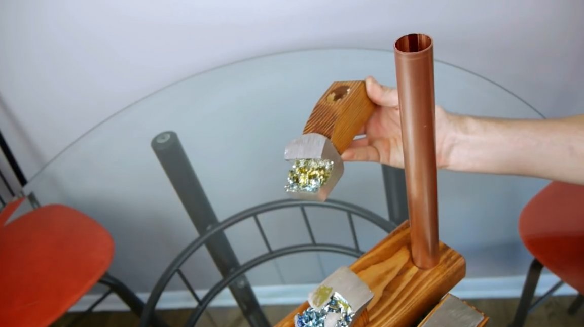
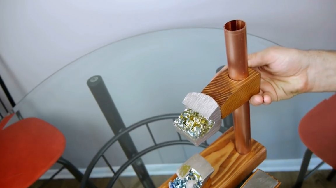
Under its weight, the panel tilts forward slightly, which prevents it from sliding down the tube. For greater reliability of fixation, you can simply grease the hole with rosin. At the same time, it can be easily adjusted if necessary.
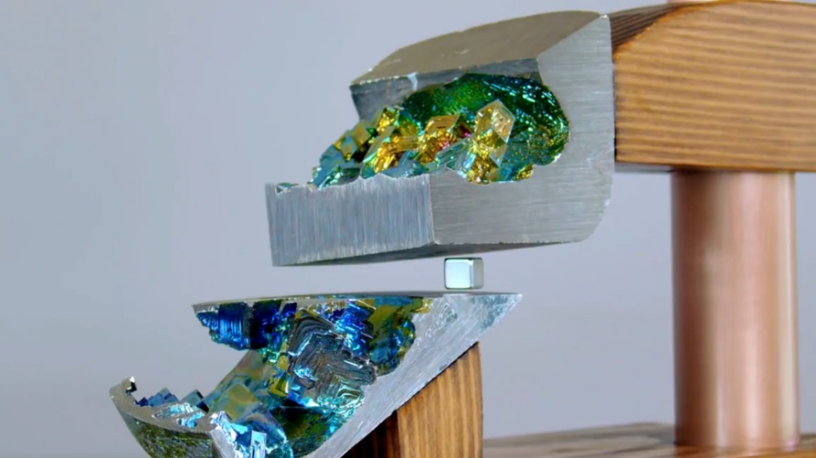
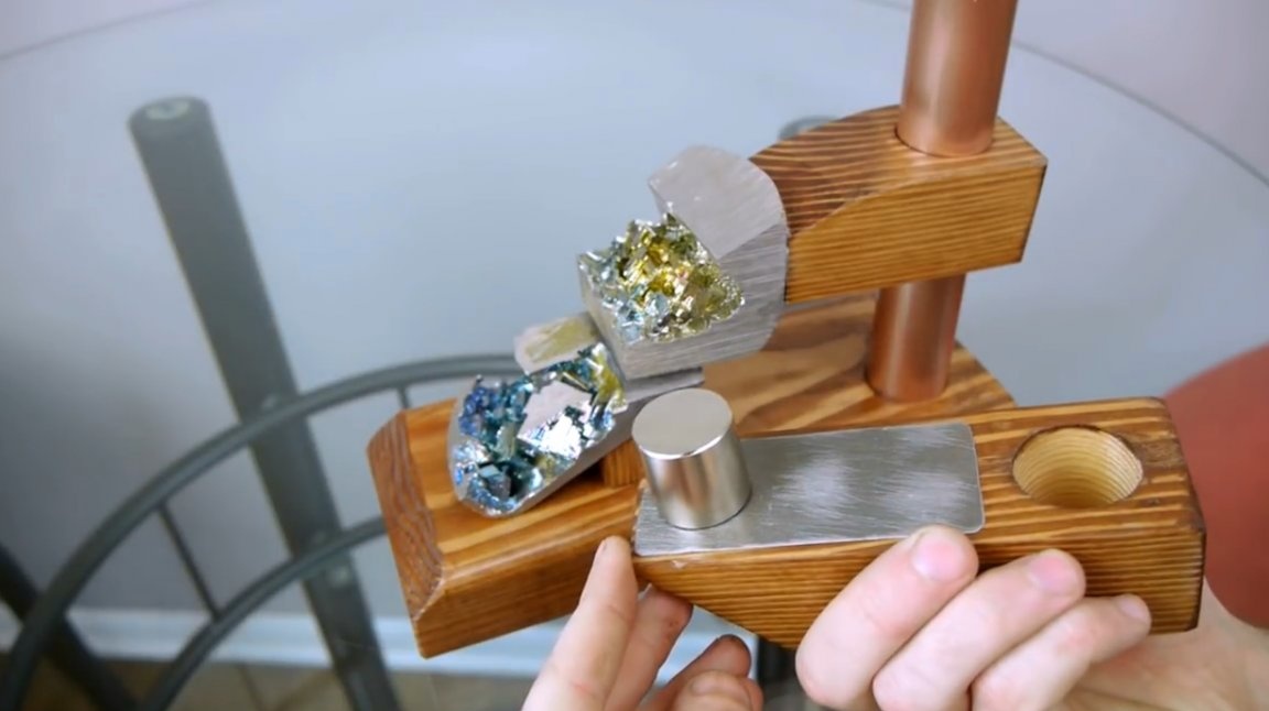
The lifting magnet is mounted on a similar wood panel to which a wide steel plate is previously attached. Now the magnet can be moved anywhere in the plate or it can be replaced with another suitable magnet, which gives a lot of opportunities for experimentation.
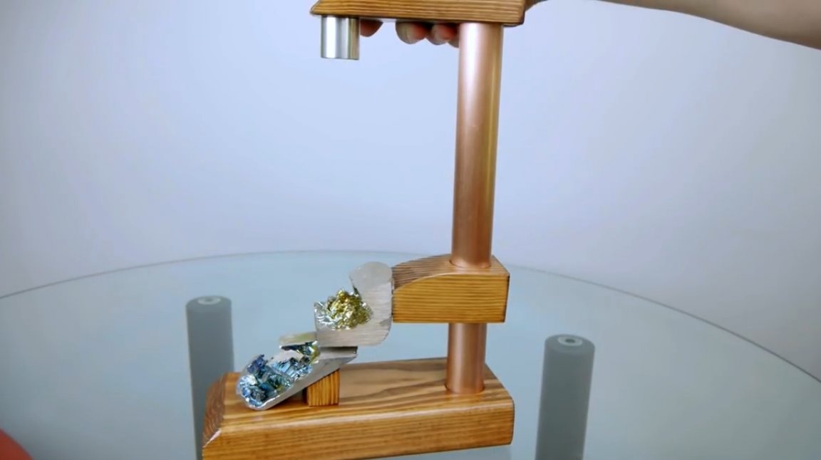
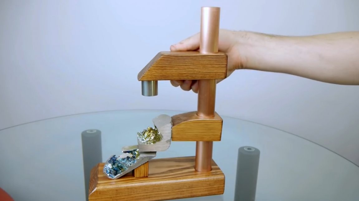
Here is such a simple and complex installation at the same time.
Thanks to the author for a very interesting experiment!
All good mood, good luck, and interesting ideas!
Author video can be found here.