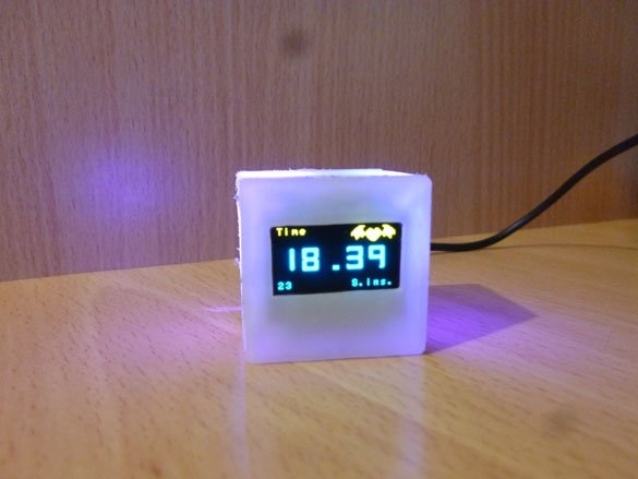
Good afternoon. I want to share instructions for making cute watches. They will be made of milk plastic. Will have a backlight. Bright Oled Screen. And the heart will be Attiny 85, or rather the Digispark Attiny 85 board. We will also connect a temperature sensor. Power over USB. You can connect to a computer and put somewhere near the monitor. And you can use the charger for the phone with USB, and place it anywhere where there is a power outlet. Well, and as always, we can do without the RTC (Real Time Clock) module. We do not need extra, and there are not many controller legs.
Let's start with the list of necessary:
- Digispark Attiny 85 Board
- Digital temperature sensor ds18b20
- Oled screen (resolution 128x64, I2C protocol operation)
- Resistor 4.7 KOhm (3.3 KOhm possible), 0.25 W
- 150 ohm resistor or match your LED
- Transistor SS8050 (or equivalent)
- 5 mm LED or SMD 5050
- Plastic 1-3 mm thick. (translucent, milky)
- ISP programmer (you can replace any Arduino pay)
- Button (needed to set the time)
- Dupont 2.54 mm connectors ("mother", "father")
- Hot melt adhesive or any other suitable for plastic
- connecting wire
- Soldering iron, rosin, solder
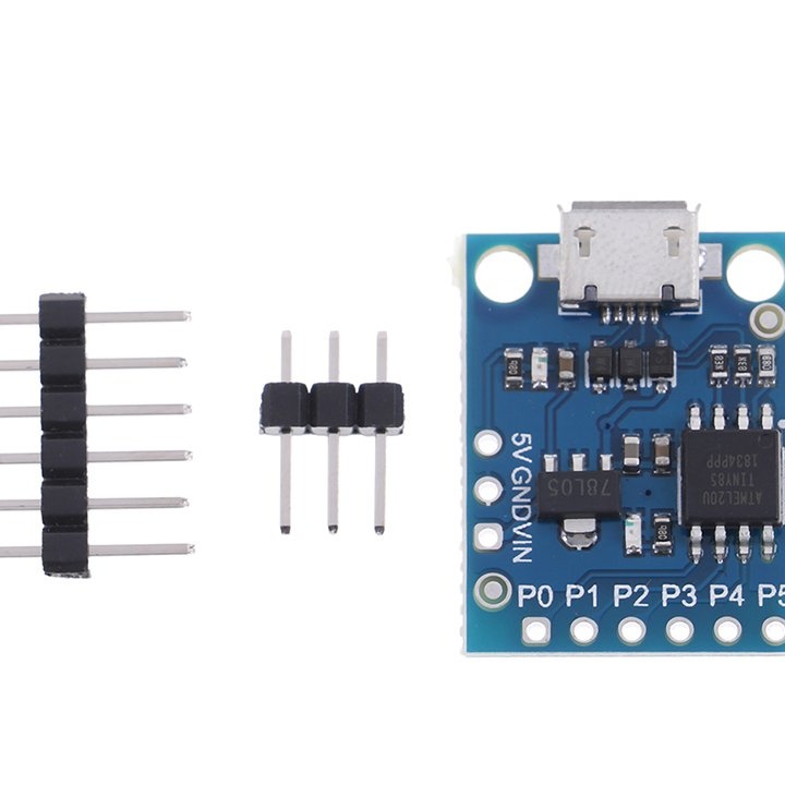
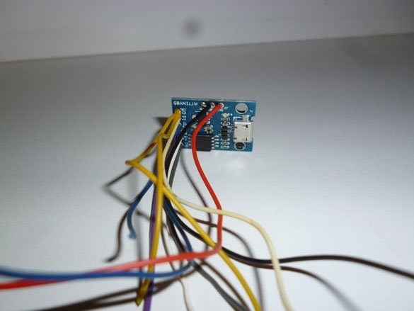
Step 1 Modify Digispark Attiny 85.
So, we have an excellent Digispark Attiny 85 board. On board it has (you guessed it) Attiny 85. You need to buy a version of the board with micro USB. Full USB in this case does not fit. But, even if you have a version with full USB, you can saw off the protruding part of the board, we will not use USB. Also there is a voltage stabilizer and all the necessary strapping. You can, of course, take the naked Attiny 85, but then the soldering and assembly process will be more complicated.
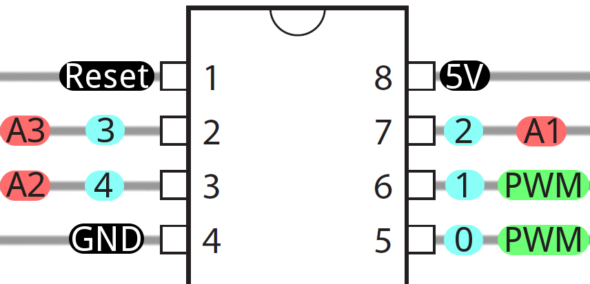
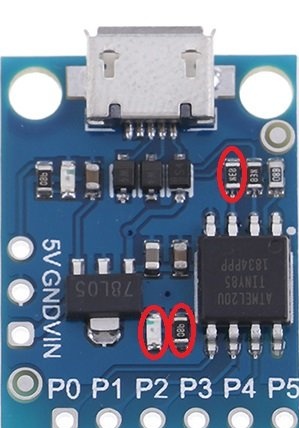
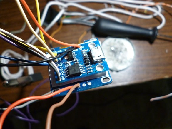
The board, as I said, is excellent, but not without flaws (flaws for this project, in another it may be a virtue). In this case, the resistor, ground pull, PB4 (3 leg of Attiny 85) will interfere with us, and the LED with the resistor on PB1 (6 leg of Attiny 85) marked them in the diagram:
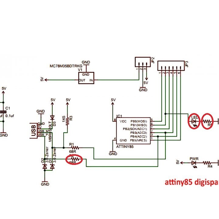
Looking ahead, I’ll say that all of the above will interfere with us. A backlight transistor will be connected to PB4. And with a pull-up resistor, it will not open (verified by personal experience). A button will be connected to PB1, which also will not work normally with a LED hanging on the line. In practice, you need to solder out or simply dig out (only carefully so as not to damage the tracks) the resistors and LEDs indicated on the diagram.
Set aside the board and take care of the case.
Step 2 Case.
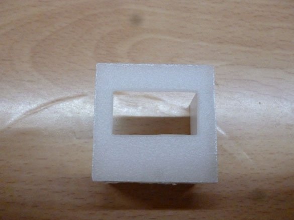
The case of our future watches will be made of translucent plastic. This plastic can be ordered in the online store or bought in a regular store (if you find). Personally, I took it from an old LCD TV or monitor. You can find it by examining the matrix. A leaf of such plastic is usually used as a diffuser, and is located between the LED backlight and the liquid crystal layer itself. Having obtained such plastic, we proceed to the assembly of the case. Our case will be in the form of a cube (simple, but tasteful). Inside the case there should be a space of 30x30x30 mm. We cut the front side of the watch, if you take plastic 2 mm thick, then the square for the front side should be 34x34 mm. This square will set all other sizes, and the walls will be glued, as it were, behind it. Having cut out the front square, we make a slot for the screen in it. We retreat from the top 8 mm, 5 mm on the sides, the slot itself should be 24x13 mm in size.
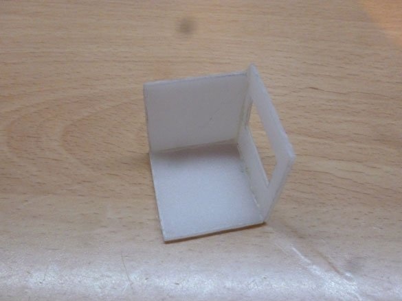
Next, cut out the upper and lower parts, they will be 34x30 mm in size (recall, dimensions are given for plastic with a thickness of 2 mm). As well as two side dimensions of 30x30 mm, and one rear 34x25mm. Then, using a hot glue gun, glue the front, bottom and one side.
On this case, we are laying aside for now. The remaining parts will be glued after installing all the insides.
Step 3 Electrician and watch assembly.
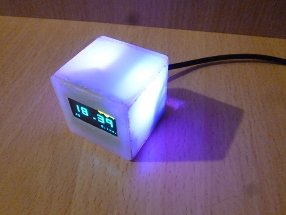
And the most interesting is ahead. We take our nice "screen". OLED (organic light-emitting diode) is a graphic display, each pixel of which is an independent LED. The diagonal is 0.96 inches. Communication - I2C bus. Resolution 128x64. To display the image, just connect two wires to the controller, which is very important for Attiny 85. Screens come in different pixel colors, choose to your taste. The most interesting seemed to me blue with a yellow stripe on top.
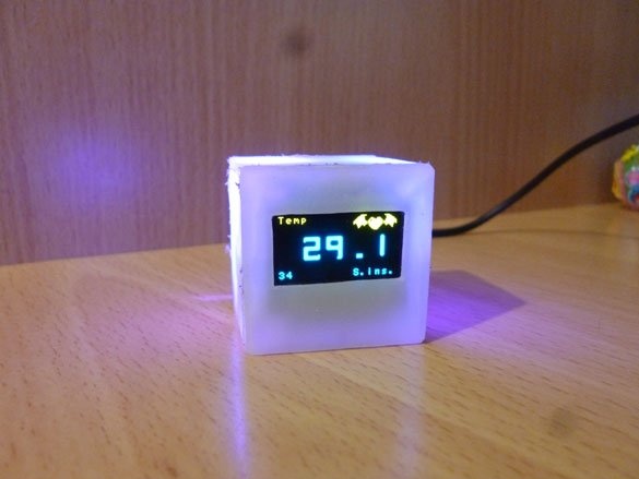
I chose a digital temperature sensor to free Attiny from unnecessary calculations. ds18b20 is connected by a single wire and works on the OneWire protocol. The data lines of this sensor need a pull up to the power line. The recommended nominal value is 4.7 kOhm, but it works fine for me even at 3.3 kOhm. Its connection diagram is as follows:
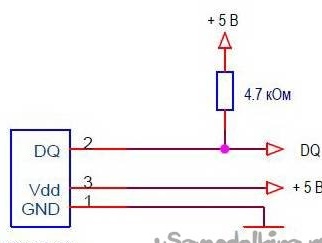
It can be connected in other ways, for example, in the parasitic power mode, but in this case, I think it is better to use the external one and connect according to the above diagram.
Next on the list is the LED. It is needed for backlighting. You can choose any color. Any 5mm LED will do. For uniform illumination of the entire case, it is better to take two LEDs. You can also shove one 10 mm. Or tricolor. This is how you like it more. At first I made a variant with two 5 mm diodes, green. But then I wanted to change the color of the backlight. Therefore, I used a three-color one in the SMD 5050 package. Resistors must be selected for the diode of your choice. I will show both options how to do it for you - it is up to you to decide.
Transistor. It is needed to control the LED, since only too low current can flow through Attiny, and when connected directly to the controller foot, the diode glows very dimly. Regardless of which LED you select or several, you must use a transistor. Ideal SS8050. But any low-power NPN will do.
We collect all this according to the scheme:
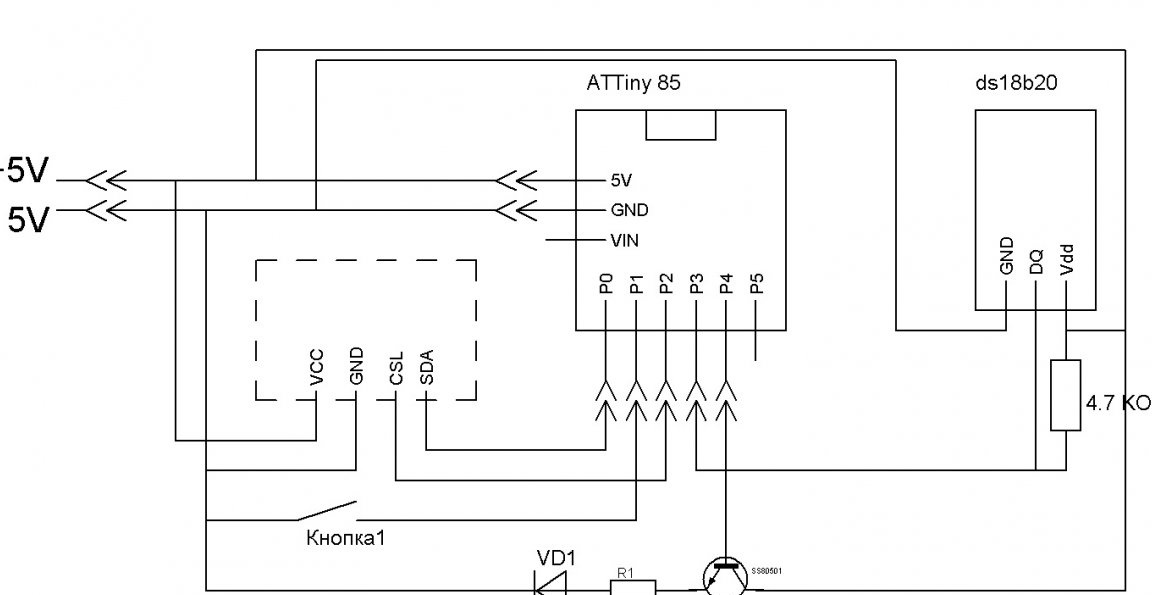
And now we’ll carry out the assembly process live:
We take the screen first.
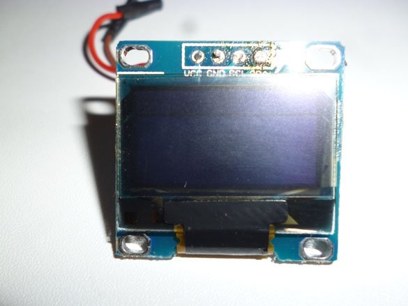
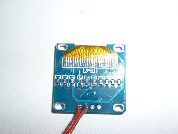
We solder wires to it, if there were “pins” at the place of contacts, they must be removed. We do the same with the modified Digispark Attiny 85.
Now, using double-sided tape or hot-melt adhesive, glue Attiny and the screen together.
We solder all other components (ds18b20, SS8050, LED and other little things). So, the first option is 5 mm diodes:
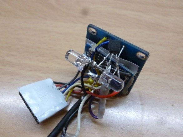
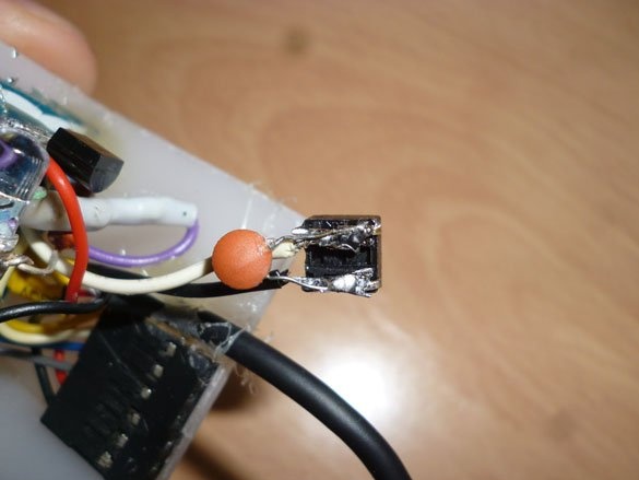
We mount the transistor by the "mounted method", for strength, you can pour hot melt adhesive:
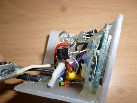
We solder the button for adjusting the clock to the occasions, it is very desirable to solder a small capacitor parallel to the button (reduces the effect of "bounce" of contacts):
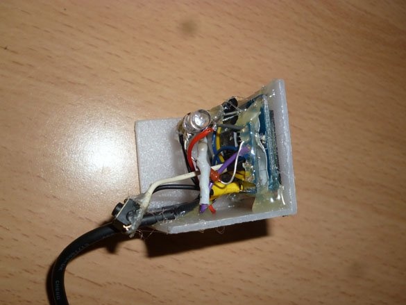
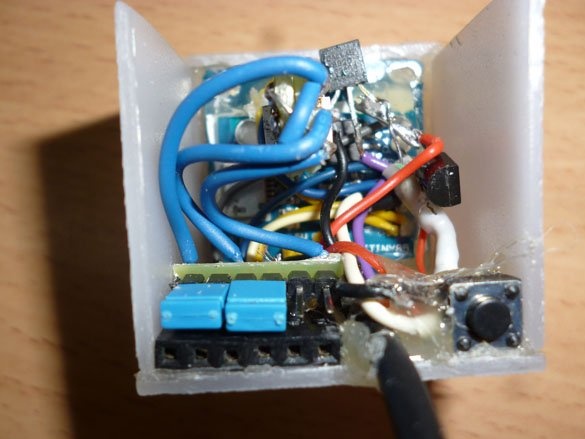
We start packing all of this in a case. First, paste the screen with Attiny:
I will describe a little the second option for backlighting. SDM diodes together with resistors must be soldered to a small circuit board. We make two identical modules:
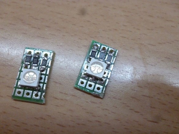
We glue two such modules together and solder them in place:
If you want one color, simply solder the wire from the transistor through a resistor to the LED leg corresponding to the desired color.
To flash our watches, it is necessary to remove the wires and connect them into one block. The following contacts should be in the block, in this order:
-PB0- - PB1- -PB2- - PB5- -VCC- -GND-We bring these wires to a single block and glue it in the back of the case, below:
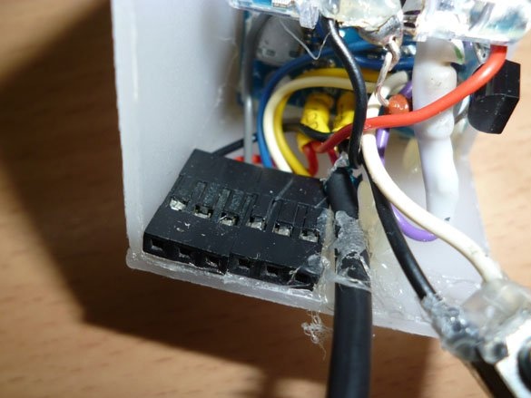
On the other hand, we glue the button from the firmware block, between them we derive the USB wire for power. Also, to make the choice of the color of the backlight, you can make another pad. The following wires should be displayed in it: a wire from the red, blue and green colors of the LED, and next to these contacts, a contact from the transistor. The control occurs by closing (jumper) of the corresponding contacts:
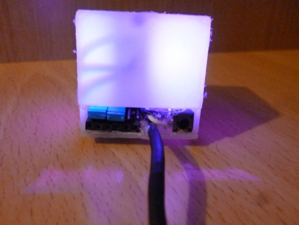
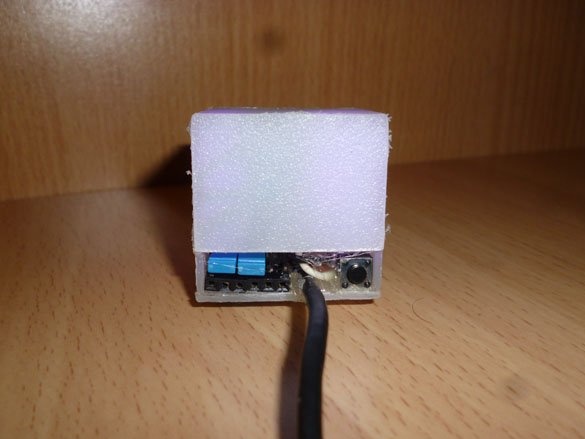
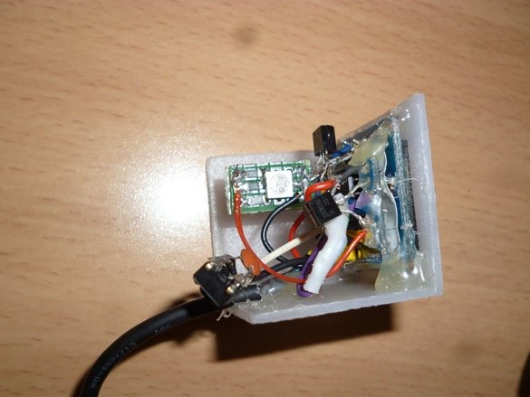
First we glue the second side wall of the watch:
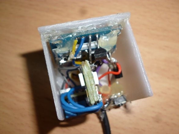
Before sticking the rest of the body, make sure that everything works. Better go to the firmware now. Check that everything works as it should and only then glue the top and back of the case.
Step 4 Firmware.
To edit and fill in the sketch (or firmware), download from the official site and install the latest version of Arduino IDE:
Arduino.cc
Then we add support for the Attiny series controllers in the Arduino IDE. We launch the development environment and go to “File” - “Settings” - “Additional Boards Manager URLs”. Paste the following link:
https://raw.githubusercontent.com/damellis/attiny/ide-1.6.x-boards-manager/package_damellis_attiny_index.jsonNow a couple more actions. Go to “Tools” - “Board” - “Boards Manager” in the search bar, enter “Attiny” and select “attiny by David A. Mellis” - “Install” and wait for the installation to complete.
Now it's time to add the necessary libraries.
For screen
Temperature sensor control
After downloading them, unpack the archives in the “libraries” folder. The desired folder is located in the Arduino IDE installation location.
As I said, all temperature sensors have their own unique address. You need to find out your address and edit the following line:
byte addr [8] = {0x28, 0xFF, 0x75, 0x4E, 0x87, 0x16, 0x5, 0x63};The clock is without RTC, so to adjust the clock you need to use the line:
if (micros () - prevmicros & gt; 497000) Change the selected value. The larger this value, the slower the clock. And vice versa.
If you have an ISP programmer, use it to fill sketch in watch.
If there is no programmer, we take any Arduino board, fill it with the sketch from the Arduino ISP examples. Connection pad for firmware:
D11 - P0
D12 - P1
D13 - P2
D10 - P5
VCC - +5
GND - GND
And fill in the sketch.
For power, you can use the USB port of the computer or charge the phone with USB:
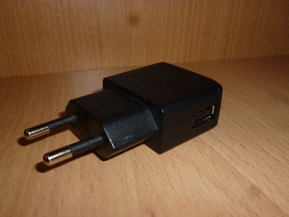
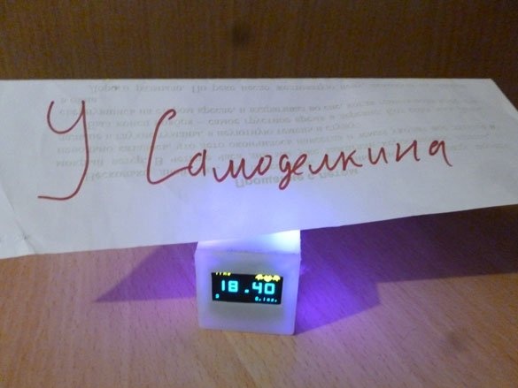
Last photo: