
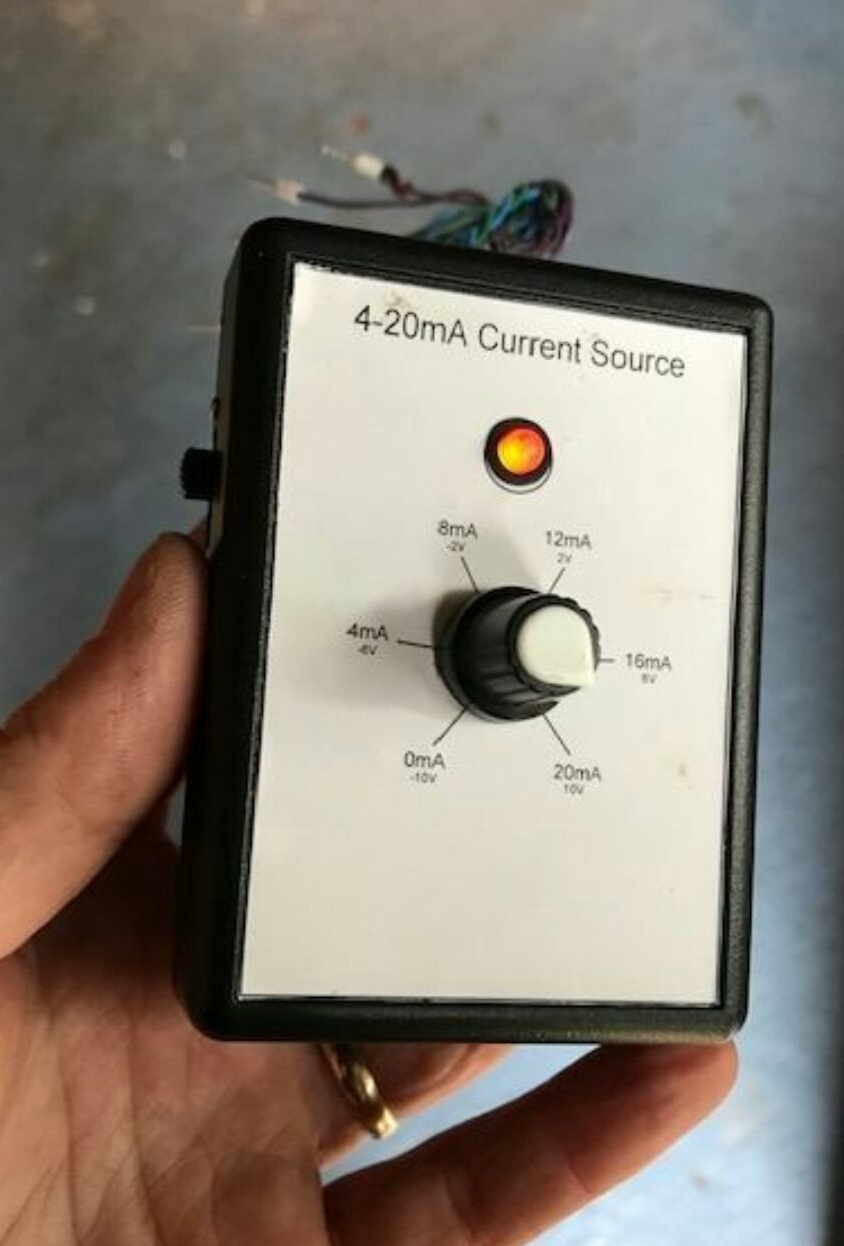
In industrial automation, sensors with current outputs from 4 to 20 mA are widely used. The first of these values corresponds to the lower limit of the range of the measured value, the second to the upper. Let me explain with an abstract example: a certain sensor measures the number of cats in the basement in the range from 0 to 500 cats. Zero cats correspond to 4 mA, five hundred cats - 20 mA. Suppose now there are 200 cats in the basement. We calculate the current that the device should issue in the line: I = 4 + 200 ((20-4) / 500) = 10.4 mA. Now we will be transferred to the side of the receiving device and calculate the number of cats on this current value: N = (10.4-4) (500 / (20-4)) = 200 cats. No requirements are imposed on the accuracy of line resistance and load in the receiver: a current stabilizer is located in the sensor, due to which the voltage applied to the line will be automatically set exactly as it is required to obtain a given current. Of course, “in production” there will be boring degrees or megapascals instead of cats. And if the current drops to zero mA, this will be considered a line break.
When adjusting the system, which includes a sensor and a receiver, it is necessary to verify the presence and correctness of the reaction of the second to a change in current in the entire range. To do this, instead of the sensor, an adjustable current regulator is included in the line, the value of which depends on the position of the handle of the variable resistor. One of these assistant devices was developed by Instructables under the name lawsonkeith. Additional function homemade is the generation of a stable voltage from -10 to +10 V and from 0 to +20 V, which is useful when setting up circuits on an op-amp.
Having a stable voltage source of 5 V and a variable resistor with characteristic A, it is easy to obtain a voltage that varies smoothly from 0 to 5 V. This voltage can be applied to a voltage-controlled current source (IITS), the circuit of which is shown below. Here R1 is the resistor that determines the upper limit of current regulation (5 V / 250 Ohms = 0.02 A), and RL is the total resistance of the line and load, when the current does not change within certain limits. The circuit allows you to simulate both emergency (current from 0 to 4 mA) and regular (current from 4 to 20 mA) situations.

Let's move on to the complete device diagram:
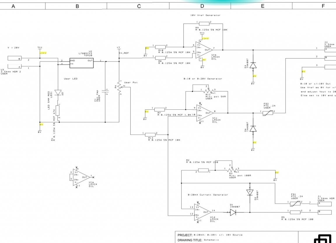
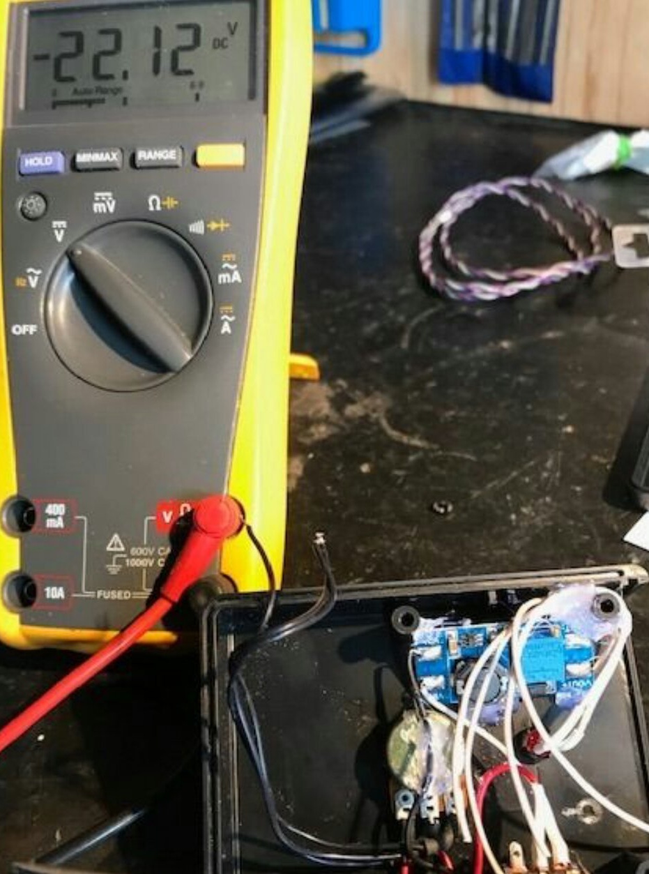
It is powered by a unipolar voltage source from 20 to 24 V (not shown in the diagram). The wizard selected a ready-made pulse boost converter powered by Krona. There is a tuning resistor on the converter board, which should be set to about 22 V.It should be borne in mind that with high humidity, even this voltage can pose a certain danger.
The source of the reference voltage (ION) in the device is an ordinary stabilizer 7805. At the first op-amp of the device, this voltage, equal to +5 V, is supplied bypassing any adjustment elements. It is turned on in such a way as to double this voltage, which is why a stable voltage of +10 V relative to the common wire appears at its output.
Also, the model voltage is applied to a variable resistor, from the movable contact of which, as mentioned above, it is possible to remove a voltage that smoothly changes from 0 to +5 V. It is supplied to the inputs of the second and third op-amps. The first amplifies it four times, allowing you to get from 0 to +20 V relative to the common wire, or from -10 to +10 V relative to the output of the first op-amp.
Finally, the third op-amp is turned on by the method described above, which makes it a source of stable current from 0 to 20 mA. The circuits on the second and third op-amps are equipped with tuning resistors, which allow the most accurate selection of gain factors.
To increase reliability, the device is equipped with protective diodes and thermistors with a positive temperature coefficient.
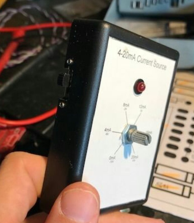
The body is selected by the master as finished, such as Hammond 1593PBK. But an ordinary junction box is much cheaper, and no worse in strength. In the front panel, the master makes holes for the LED and a variable resistor. The small diameter hole is intended for a latch that protects the housing of the variable resistor from turning.
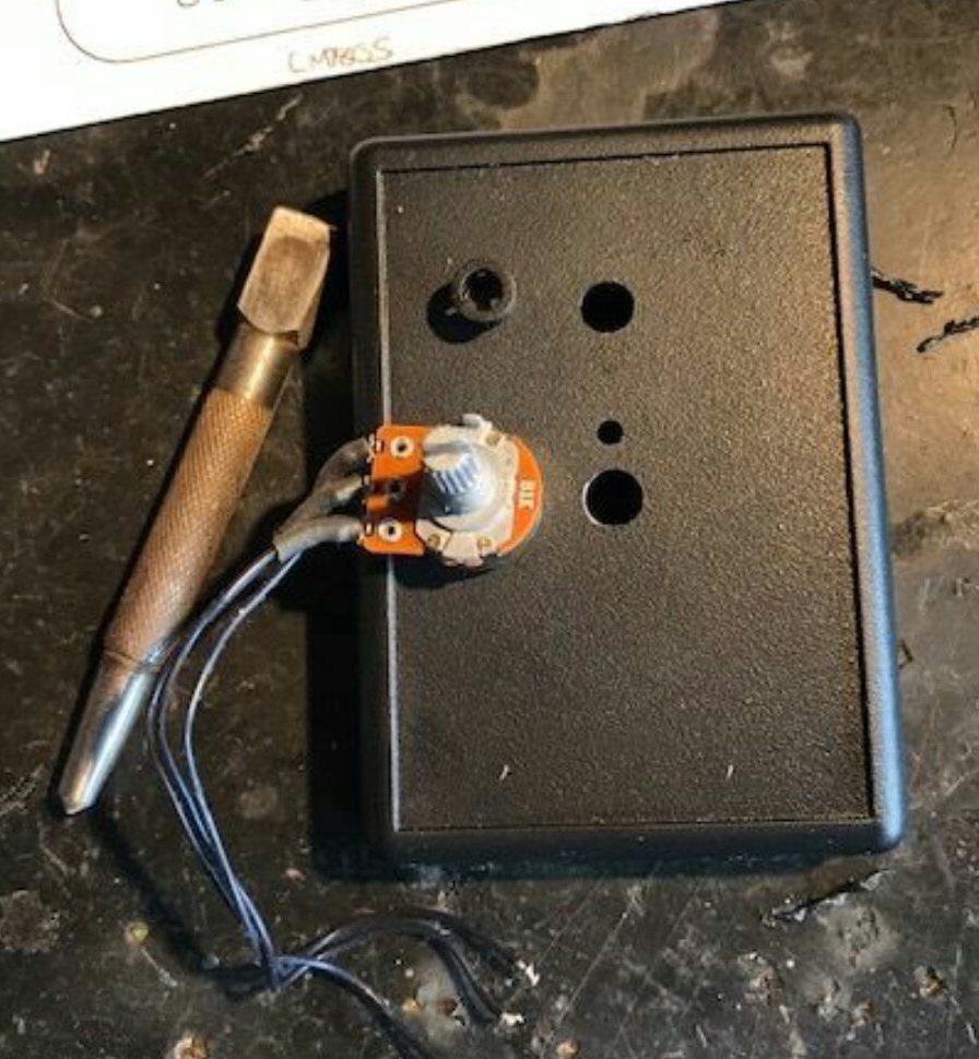
On top of these holes, the master glues the scale, aligning the circles on it with the drilled holes:

Then he puts in place a variable resistor, LED and power switch:
The front panel of the device is ready:
The wizard adds a boost converter to the device:
And it adjusts it to a voltage of the order of 22 V (very high accuracy is not required here):
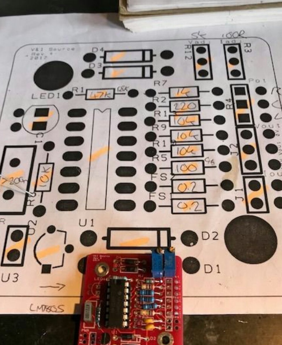
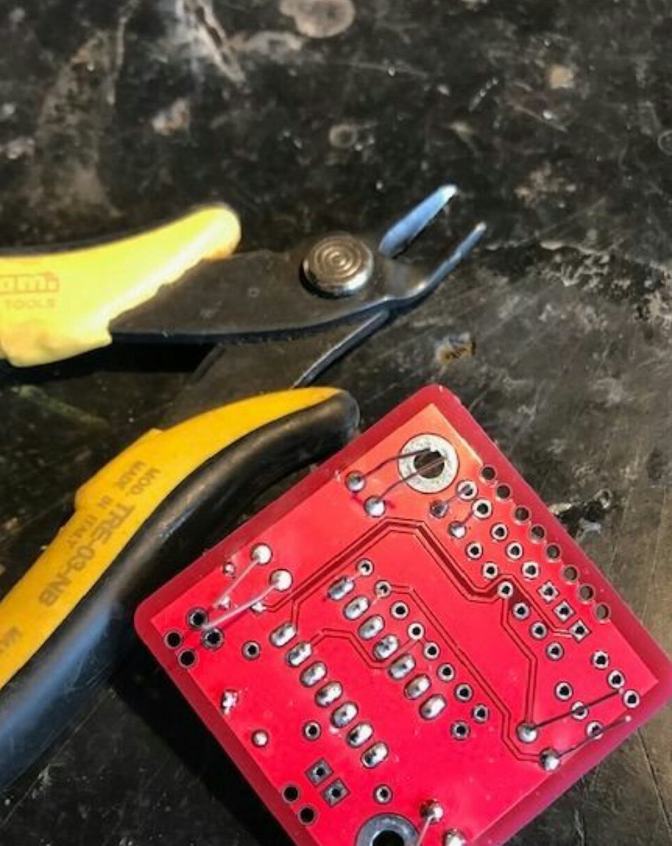
Taking the LM324 chip containing as many as four op-amps (one of them will remain idle), the wizard assembles the circuit on a printed circuit board, but a mock-up is also suitable:
Makes probes:

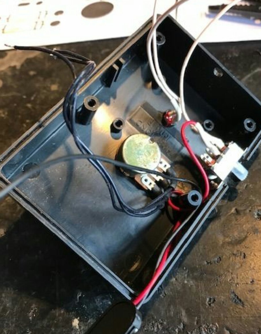
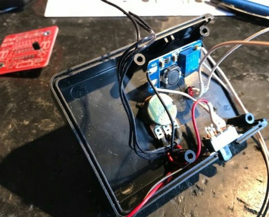
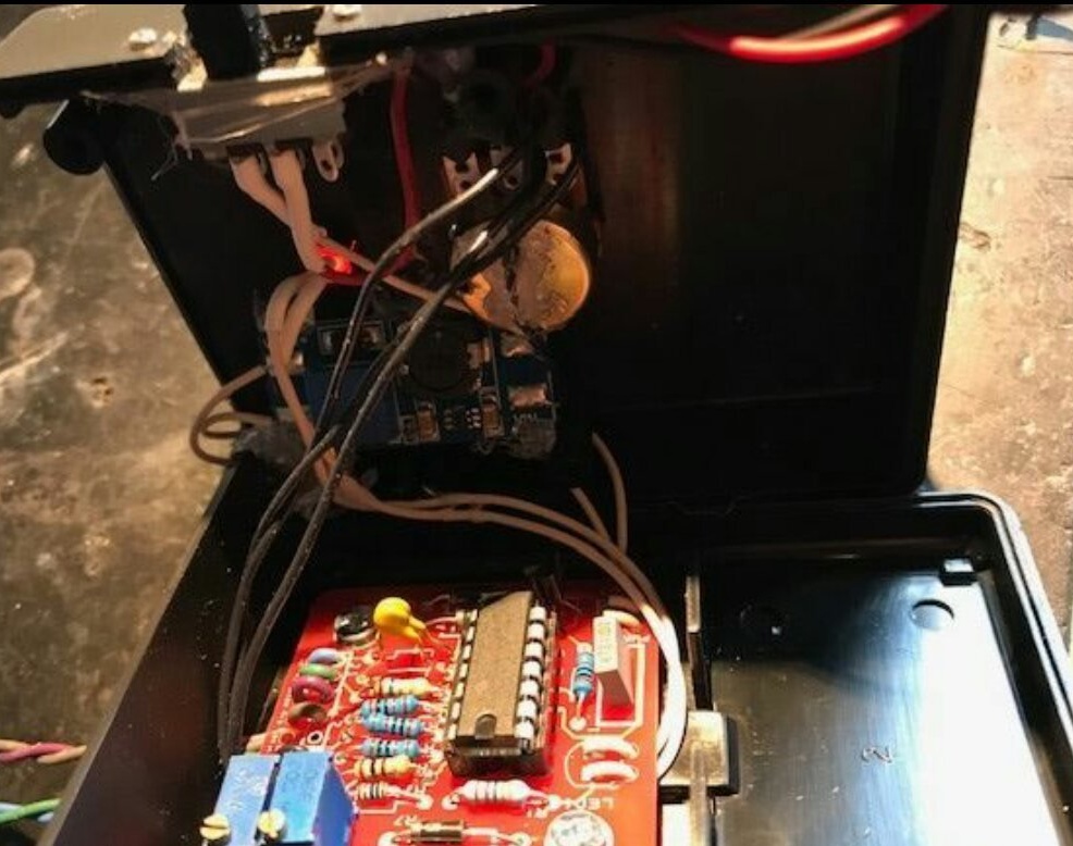
Places the board in the case and connects it to the boost converter, LED, variable resistor and probes:
Finally, the wizard begins to test the device:
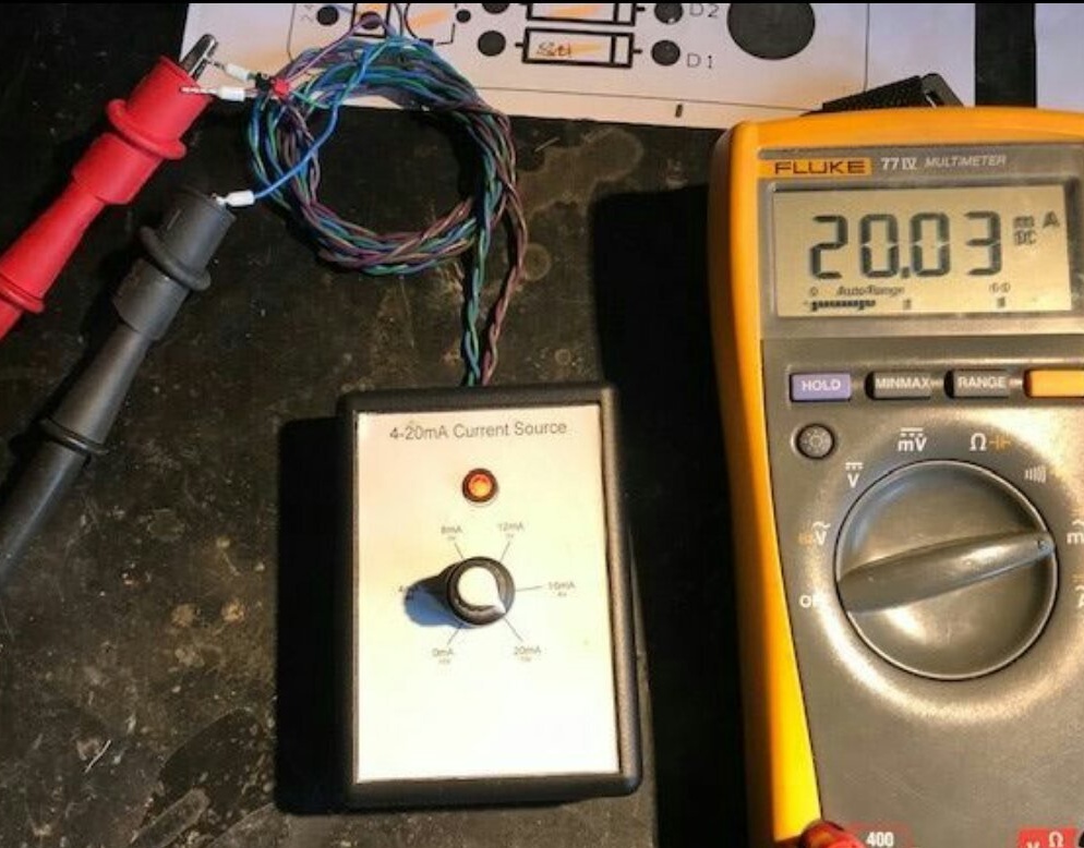
Check is necessary:
- voltage +5 V between the output of the stabilizer 7805 and the common wire
- voltage +10 V between the output of the first op-amp and the common wire
- voltage, smoothly changing from 0 to 20 V, between the output of the second op-amp and the common wire
- voltage, smoothly changing from -10 to +10 V, between the outputs of the second and first op-amp
- current, smoothly changing from 0 to 20 mA, at the output of a current source collected at the third op-amp.
When using the design, you can additionally control the voltage or current with the same multimeter. When measuring the voltage generated by the device, it is switched into a voltmeter mode and connected in parallel to the output. When measuring the generated current - switch to milliammeter mode and turn on the circuit in series. Smoothly changing current or voltage, depending on what the receiving device is designed for, observe its reaction to what is happening. In this case, it is impossible to prevent the creation of dangerous situations by actuators controlled by the receiving device.