» Topics » Advice »50 Hz mains filter

50 Hz line filter

Hello, dear authors, journalists and readers!

I'll tell you about my homemade.


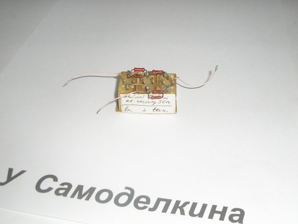
This is a 50 Hz mains filter.

How can it be useful.

Anyone who is involved in amplifiers, sound and measuring equipment, knows what the background of alternating current. Getting rid of it can be difficult.

As a basis, I took the double T bridge.

The principle of its operation and calculation of elements is quite complicated.
This is described in various sources, you can read if you wish.

With fine tuning, it can greatly weaken the noise, and also not introduce noise, since there are no semiconductors (transistors) in its circuit.

And does not require a power source. It has small dimensions.

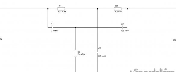
This is a schematic diagram.


I pointed to homemade entry and exit. Although I suppose that they are reversible, I did not check, there was no need.

The following details were used:

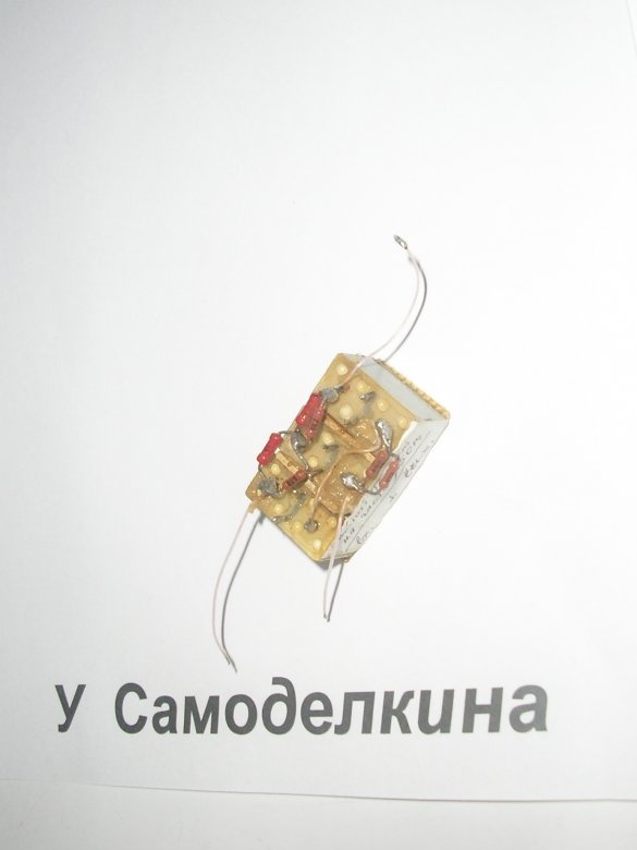
Three identical capacitors KMBP and six resistors MLT 0.125 watts. In the diagram, I showed only three resistors, and six in the photo. This is due to the fact that I did not have exact values ​​and had to be selected using a digital multimeter by parallel connection.


Materials:

Solder, a small piece of unfolded textolite, a little glue and a mounting wire and solder.

Instruments:

Soldering iron, wire cutters, scissors, tweezers and a scalpel.

When repeating the design, the following should be considered.

Capacitors can be taken KMPB, MBM and others, except ceramic and oxide (electrolytic). These types have a strong temperature dependence of capacity.

If possible, select the ratings of the parts using a digital instrument. From the selection accuracy depends on the suppression quality of the network pick-up of 50 Hz.

Or look at the percentage accuracy of the part rating. +/- 5% already gives good noise reduction quality.

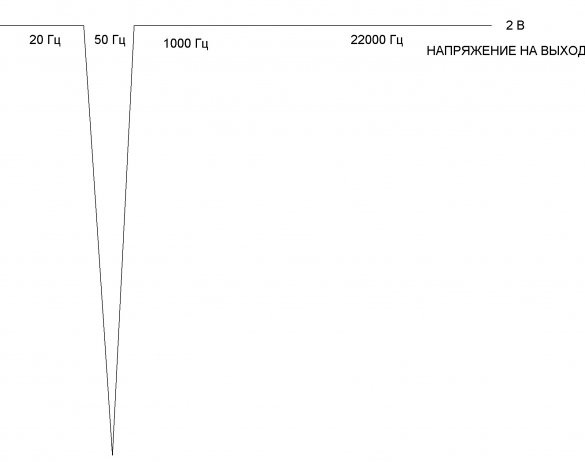
On the graph, I showed the frequency response of the device. Of course, in practice it is somewhat smoother.


In conclusion, I will add. By changing the ratings of the parts, the filter can be made to suppress interference of a different frequency.

Sincerely, author.

Suitable for topic

Related topics

Add a comment

    • smilesmilesxaxaokdontknowyahoonea
      bossscratchfoolyesyes-yesaggressivesecret
      sorrydancedance2dance3pardonhelpdrinks
      stopfriendsgoodgoodgoodwhistleswoontongue
      smokeclappingcraydeclarederisivedon-t_mentiondownload
      heatirefullaugh1mdameetingmoskingnegative
      not_ipopcornpunishreadscarescaressearch
      tauntthank_youthisto_clueumnikacuteagree
      badbeeeblack_eyeblum3blushboastboredom
      censoredpleasantrysecret2threatenvictoryyusun_bespectacled
      shokrespektlolprevedwelcomekrutoyya_za
      ya_dobryihelperne_huliganne_othodifludbanclose
74 commentary
Author
Guest Eugene,
Yes, 8.2 kOhm these resistors. But the "trick" is that it is a bridge where you can use a variety of resistors and capacitors, but strictly in a certain ratio. In the discussion of this my homemade read. Options can be very different. BUT, some calculation formulas need to know.
Guest Eugene
Hello. Thank you for sharing the scheme.
Unfortunately, I can not read only the value of resistors 1 and 3. Specify, please. 8.2 kOhm, right?
You, besides the title, would also read the article itself before inserting irrelevant pictures. ((
I use such a scheme
How easy it is to fail, without even understanding the topic, how easy it is to fail ...
ded70sgakomlet
Accidentally stumbled upon this nonsense of poorly educated vocational schools. This is chamber number 6! And does this R555 believe that it knows something from radio engineering? And what aplomb, and how much conceit ... Sheer shame. He imagined if my students of 40 years old would carry such nonsense ... Some kind of nonsense!
Author
Personally, I used and use this filter when observing and measuring various weak signals indoors, where there is inevitably a powerful 50 Hz network pickup. I have to repair various medical equipment from time to time. And I know very well how much attention is paid in electrocardiographs to suppression of a pick-up of 50 Hz. It is 50, not 100, as you say, with regards to power supplies. Where the ripple is 100 Hz ALWAYS BETTER, EASY suppressed by rectifier filter capacitors rather than 50 Hz. Have you ever collected a transistor noise meter? Try it, then you will find out that you can’t do without such a filter. Why, precisely without this, and not, say, on a transistor or opamp? But because the noise of the transistor and the opamp will negate the operation of the meter. And my filter is assembled on passive elements and introduces a minimum of noise into the transmitted signal. Have you collected a nonlinear distortion meter? If you collected, even the simplest one, with an error plus minus bast, even on batteries (that is, with a galvanic isolation from a 50 Hz network), you should know that without this or a similar filter the meter works WILL NOT. And you collected amps, which, as you say, the frequency begins with ZERO (0) Hz. Are you listening (hear) frequency 0 Hz, i.e. direct current ?! Are its speakers reproducing well too? xaxa xaxa xaxa
Wal
I still don’t understand where this miracle device can be used, although I am involved in amplifiers, sound engineering and measuring equipment?
In the power supply? So there after the bridge you need to filter 100Hz, and not 50?
Amp input? So he has a frequency with 20 Hz, and even from scratch starts and a failure at 50 Hz no one needs. Where to stick this creation ???
Author
I’m laughing at you! xaxa You can’t even write insults against me correctly. Moreover, you are clearly far from electronics and you will not be able to criticize me on the merits of this homemade product. Therefore, RELAX.
Useless_unit
Without a useful thing !!!
You can put it in your ass!
Author
That's right. It is a pity that the New Standard disappeared somewhere, does not read us. But I wanted to offer him this particular ms for an interference-free motion sensor. He was interested in this topic. I tell everyone. The chip is cool and costs a penny. A minimum of additional elements, and so many wonderful and simple homemade products can be made on its basis.Personally, I collected on its basis: counters of moving objects and people, security devices, light and music installations, equipment for wireless control of models, voice control devices (yes, you heard right), then I will add how, and much more. Read datasheets on ms 567, LM567, NE567. And in my workbook, a page 12 years ago shows how I tortured this ms by applying not only a sine to the input, but also a saw, even a rectangle. The microcircuit showed high selectivity and stability. And the output can directly connect a small load. In the notebook you can see that he connected the LED. good shok
I read about this IP. At a superficial glance, the most logical application is in security systems based on IR sensors: it is simple, noise-immune and does not depend on temperature and aging of timing elements.
Author
Ivan_Pokhmelev. Flipping through his old workbook about 12 years old, I came across my notes on testing the tone decoder 567. This is not a filter, but a highly selective one (there aren’t enough words, what a miracle this chip is, with a minimum of binding). Judging by the values ​​of the capacitors exactly 5000 pF, I took a typical switching circuit from some foreign book. Now I remembered how many wonderful home-made products based on this ms, it’s LM567, NE567. Let's discuss how it can be applied.
Quote: R555
You wrote that you have the feeling that autumn has already arrived. And you look, the date you wrote it. You, apparently, have a delay in awareness of reality. Contact a psychiatrist. Perhaps they will help you. And, maybe, they will blame on Durkee for life.

In the fall, people like you become aggravated, which is what is actually happening now. Moreover, it is immediately obvious that you know from experience who you should contact and where they will go after that. Use your own advice.
Quote: R555
And now you wrote that I’m not worthy of criticism, that I’m trying to introduce Novichkov to electronics

I did not write such nonsense, you thought up it to yourself. I wrote that newcomers can mistake you for being smart and listen to your words. This is a fundamental difference with the meaning that you came up with for yourself.
Quote: R555
that I'm a thief, stealing other people's schemes without providing any evidence of this

You yourself have provided evidence of this, re-read your messages.
Quote: R555
You crossed the line of reality, not noticing that they communicate with me, those who are on the site FOR YEARS earlier than me. By this you insulted THEM too.

Said a man from beyond, connecting the VCRs. Once again, I don’t care who and how communicates with you. I’ll also clarify specifically for you that I don’t insult you, but only tell truthfully and frankly what I think and if it really hurts your eyes, then this is your problem. Especially since you should not insult people, for some reason attributing them here. If I wanted to say something to someone, I would do it without your help.
Author
You wrote that you have the feeling that autumn has already arrived. And you look, the date you wrote it. You, apparently, have a delay in awareness of reality. Contact a psychiatrist. Perhaps they will help you. And, maybe, they will blame on Durkee for life. And now you wrote that I am not worthy of criticism, that I am trying to introduce Novichkov to electronics, that I am a thief, I steal other people's circuits without providing any evidence of this. You crossed the line of reality, not noticing that they communicate with me, those who are on the site FOR YEARS earlier than me. By this you insulted THEM too.
Pay attention that I don’t care who and how he addresses you. Also note that in order to start criticizing a person, he must first do something. You are not worthy of criticism, you only stole other people's schemes. My comment appeared only because I speak only directly and the truth. Nobody, except for those new to electronics, will repeat such “schemes” after you.And because you rush with clever words, newcomers may mistakenly consider you clever, which will be fundamentally wrong.
Author
I get it.
Author
Wow, how sophisticatedly offends! Thief, made by hand, crazy, etc. But you relax. How do you write that I will throw you poop right now. I won’t. You yourself smeared with excrement in front of the community. Please note that even those who criticize me turn to you. We have a certain etiquette here. Do not think that on the Internet you can insult, be rude, be rude. You can get on the scoreboard, as in real life.
I do not want to offend anyone, but I have to, it feels like I'm reading crazy nonsense. I was even more convinced of this by reading the next branch about the imperfection in the form of completely unnecessary garbage, with a partially mop-up circuit, for connecting twenty years as a dead technique in the form of video recorders and other necrorarity. It feels like autumn has already arrived. Now author, although what the hell is the author, he pioneered both of these schemes as "Denispopov" and gave them away along with well-known jambs, so now of course he will throw me poop, but this will not change the truth - a thief and a handjob fills himself with every comment .
Quote: R555
You still found that Soviet book of 1964

2 minutes after I read your message, and after 5 minutes I read it .;)
Tricky people make mechanical devices with extremely low losses, hide additional recharge from gift sources in them and claim to have created a VD. )))
The classic double T-bridge has two circuits: one - 2 capacitors and a resistor in the middle, the second - 2 resistors and a capacitor in the middle. In the generator on the EP, the bridge is different: one circuit - a capacitor + resistor and a resistor in the middle, the second - on the contrary - a resistor + capacitor and a capacitor in the middle.
So, it seems to be similar, but the scheme is completely different.
R555 “To the Figs. The Higher Forces did not give the nod.” So they said to the Figs)) Greedy, however, the Higher Forces do not give more than 99% and do not share their forces, but they say that they created the world)). Let’s tell if it’s not a secret that you are there, maybe send this to the self-made one: “a circuit based on the principle of resonance of an LC circuit with energy return back. And I achieved an efficiency of about 99 with a penny
Author
New Standard, I think I get it! Do not be lazy, at the very entrance of the telephone line into the device, make several turns of wire (recall, simultaneously, two wires) on a ferrite ring. If there is a ring of a decent diameter, you can simply pull out the standard connector from the telephone and push several turns into the ring. Simple and fast. I’m very interested to understand what kind of tip this tricky one is. Although, that's all, I'm sure. High frequency interference on the telephone line. And I realized this when you wrote about the beat of a beep. If winding the telephone line ring does not help, I know what to do. We will destroy this obstacle, be it wrong!
Author
Ivan_Pokhmelev, of course, there is no power amplification in these circuits, otherwise we would have made the Eternal Engine long ago. I'll be honest. At one time I was engaged in an alternative with my associates. So, I made one circuit based on the principle of resonance of an LC circuit with energy returning back. And he achieved an efficiency of about 99 with a penny%. Everything, I think, the perpetual motion machine is created. Figwam. Higher powers have not given the go-ahead. Then I looked on YouTube vidos. There, one Georgian made a similar installation, though the size of a mini-tractor and publicly (the public, I suppose, has his own), powered up his house and all the lighting in the yard. I think kilowatts so 5. Quack.
Author
Ivan_Pokhmelev. I am very happy.As soon as you wrote about the emitter repeater and 1, 207, I realized that you still found that Soviet book of 1964 that I said. But why do you write that this is not a double T-bridge? On the other page (32) it is written. Double T-shaped, unbalanced. The keyword is unbalanced. But T is a bridge.
9 V - PSU or battery?
R555 Well, what is there to draw a landline phone powered from 9 to the power supply, but when you pull the 9-volt wires (power) by 10 meters, a tip appears in the handset (it goes along with the beeps at the same time), power interrogation does not give anything. Or maybe the feedback between the power cord and the telephone line, or is there a lower pickup frequency than the drosel can pay off?
Quote: Nruter
There is such a thing as resonance.
In resonant RC circuits, that LC circuits can be amplified either by current or by voltage, but they cannot amplify by power, they only redistribute the energy of an external source with some loss in its internal resistance.
In the emitter follower oscillator, where the theoretically possible coefficient of 1.207 is indicated, this circuit is not a classic double T-bridge, but another circuit, asymmetrical.
Author
New Standard, as you say, white noise, interleaving with a background of 50 Hz, receiving radio stations. This does not seem to be in nutrition, but in entry. Case is not an external antenna? Then the antenna cable must be filtered. This is done almost as I advised. Nearly. The main and surprising thing is that the useful signal is not attenuated. If not dumb, draw a diagram of the entire installation by hand. Perhaps I can give important advice.
Quote: R555
How can a circuit of passive components, without a power source, amplify?

Elementary. There is such a thing as resonance.
But this does not apply to the filter under discussion. The operation of a notch dual T-shaped filter is based not on resonance, but on a phase shifter. It is at a frequency of 50 Hz that the output signals from both T-chains have the same amplitude and phase shifted 180 degrees. Since the elements under discussion in the filter under discussion are incorrect, the amplitudes at the outputs are different, although the phases are deployed correctly. Therefore, the suppression is weak.
R555 and Ivan_Pokhmelev It looks like in a laptop power supply before entering the computer throttle? Oddly enough, I did so, but there was no result. Forked wires but not very good (on the 10m line, but already on the throttle well pitching between themselves). The pickup was like some kind of white noise with a 50 Hz mix and different radio stations, maybe it was from the line, or feedback, but why was it not from the power supply from the PSU?
In addition to the R555 ferrite ring tip, be sure to twist the wires. Twisted pair is a very effective way to suppress common mode interference.
R555
What can you say about the apogee of popular thought?
Well, what can I say? Goal for fiction is cunning! Russian land will not become scarce with talents! The first available tape recorders appeared much earlier than the SG-Sh connectors, and lived long after the appearance of these connectors! And then it was problematic to get a good shielded wire, they sculpted from what it was, and not everyone had enough basic knowledge!
Author
Korolev. A friend brought me a bag of gifts from the people. I sit, make out what to throw out, what to leave. Rzhu nimagu. Found a miracle cord, the top of folk inventions. The signal from the radio point through the plug (it can also be plugged into a 220 V socket) is fed directly to the tape recorder. At the same time, along the length of the network wire, the signal passes to the length of the shielded wire, then to the box of the famous company Octave, from the box again to the screened wire.And, apparently, he walked further (circumcised) This is pipets! Especially if 220 immediately to the mafon! I will take a high-quality screened wire (a dense, tinned stocking) and an Octave box from this cord, and you can mount some homemade work in it. What can you say about the apogee of popular thought? I hope my photo has attached.
Author
New Standard, I said that I’m doing transmitters. So, I recommend the method. Carefully ! At the very exit of the power wires. Both wires make several turns on a ferrite ring. Further, the wires can have a sufficiently large length. To sculpt garlands of capacitors with chokes is not necessary.
Ivan_Pokhmelev So, I once connected external power supply 9 v (crown) to the power of a stationary telephone with short wires, then I extended the power wires and put them back by 10 m (well, I had to extend it), after which there was a terrible tip in the phone’s handset, I just didn’t (big ones have grown,
electrolytes, even partially shielded but not much), what’s the matter, why didn’t the tip go?
Author
Yes, 100 Hz is often present in interference. When straightened by a bridge, a double ripple appears. Ivan_Pokhmelev, by the way, remembered. We saw, often parallel to the diodes in the rectifiers 50 Hz put ceramic capacitors of small capacity. Why do you think this is a perversion? I have my own version.
Author
Yes, nobody canceled the shielding of wires. And also. They paid attention to how in the lamp equipment the filament wires of the lamps are twisted. It helps. It is advisable to place power transformers in special screens, now this is rarely seen. Today, put things in order in their stocks, 2 of these trance caught from disassembled Taiwanese monitors. Put aside, an interesting idea came.
improve power supply filtering.
And to properly shield the input circuits.
If we press, then not 50, but 100 hertz, if a conventional transformer power supply is used. But this is the wrong way for the examples you cited, the right way is to improve the filtering of the power source.
Khatul Madan The filter can be placed at the input of the amplification path of an audio frequency, for example, a VHF receiver, radio stations or landline phones that are powered by an outlet, it presses almost only 50 Hz and the quality of the remaining higher sound frequencies remains excellent
Quote: R555
Yu.A. Andreev, B.G. Volkov. Measuring equipment on transistors.
And where is there about K = 1.2? On what page?
Quote: R555
Curious, is she on the web? Take a look and let us know.
Have you been banned from Yandex with Google if you give out such instructions? )))
There is another option, why such a bridge: the author deliberately reduced the suppression at the notch frequency, while at the same time expanding the suppression band slightly to compensate for the departure of the bridge parameters and the “walking” of the network frequency.
Author
Ivan_ Pokhmelev, well, I give a link to a 1964 book. Yu.A. Andreev, B.G. Volkov. Measuring equipment on transistors. Publishing House Energy. 1964 year. Here she is in front of me, battered, I don’t even know how she got to me. Curious, is she on the web? Take a look and let us know.
A little stupid: distracted and sent, without checking. ((
Not the "final version," but the "final result."
Quote: R555
I found a Soviet book, ...
In another Soviet book of 1964,
Usually, when you refer to a source, it is customary to call it.
Quote: R555
In another Soviet book of 1964, which I found yesterday, secret values ​​of the details of the double T bridge are given, in which it turns from a fence ... it turns into a circuit with a transmission coefficient of 1.2, that is, it amplifies the signal !!!
"Do not read Soviet newspapers before dinner!" © M. Bulgakov
If in this book it is written about the "fence" filter and the "coefficient", then it is hardly credible. Especially if there the RC circuit amplifies the signal. )))

We advise you to read:

Hand it for the smartphone ...