
Greetings the inhabitants of our site!
The time has passed when soldering stations were expensive and not as affordable as they are now. It used to be no Chinese online stores and trading floors, and radio amateurs bought soldering stations for fabulous money. Nowadays, of course, everything is a little different. The market is literally littered with cheap copies of Japanese stings.
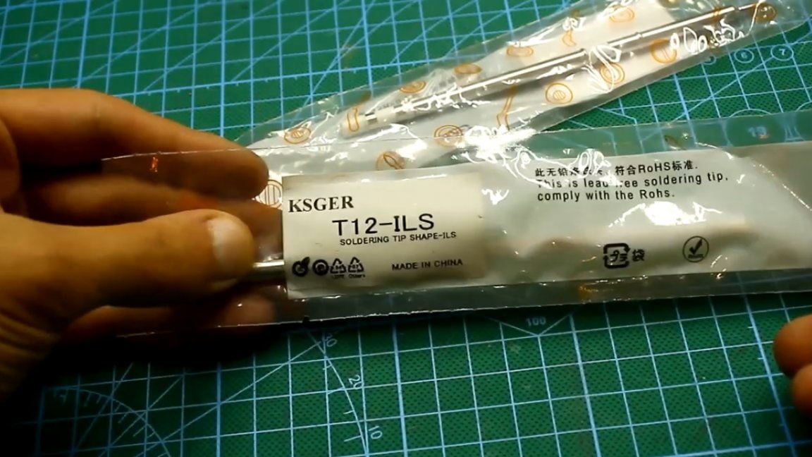
These stings made a real revolution. They can heat up to operating temperature in a matter of seconds and also have a fireproof tip.
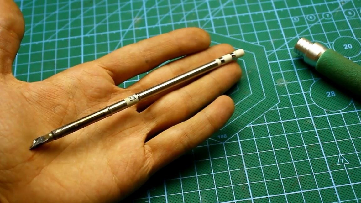
In such stings, the thermocouple is located very close to the tip, this allows the soldering station to instantly respond to changes in the temperature of the sting, which in turn makes it possible to control the temperature of the sting with high accuracy.
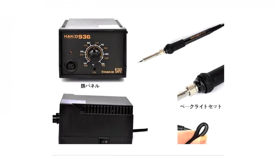
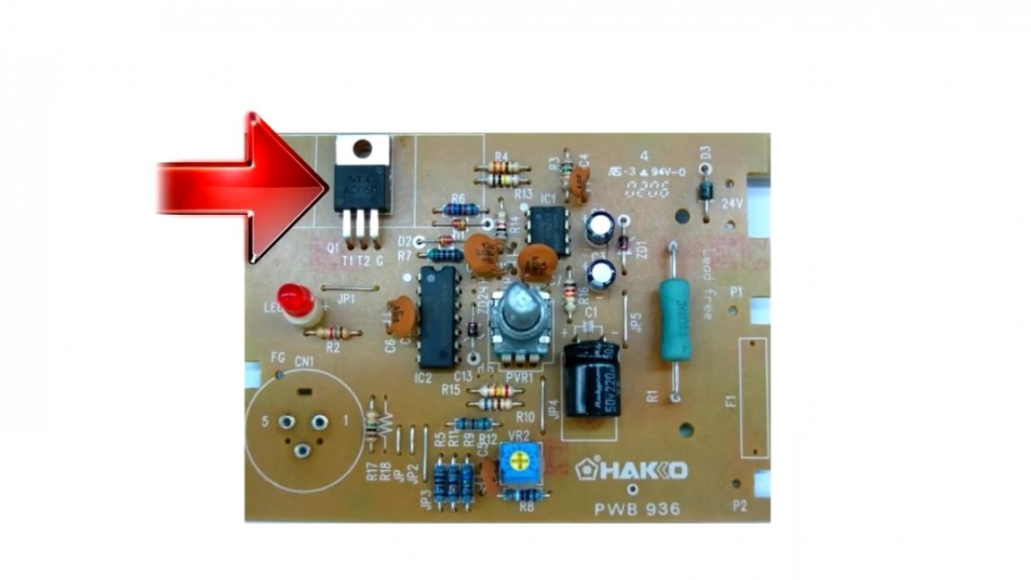
But there was something even more popular with Hakko - this station:
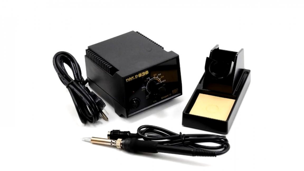
This is a regular analogue station. There were countless clones of this station; literally everyone who was not lazy was engaged in the production of the 936th station, and it was the most accessible.
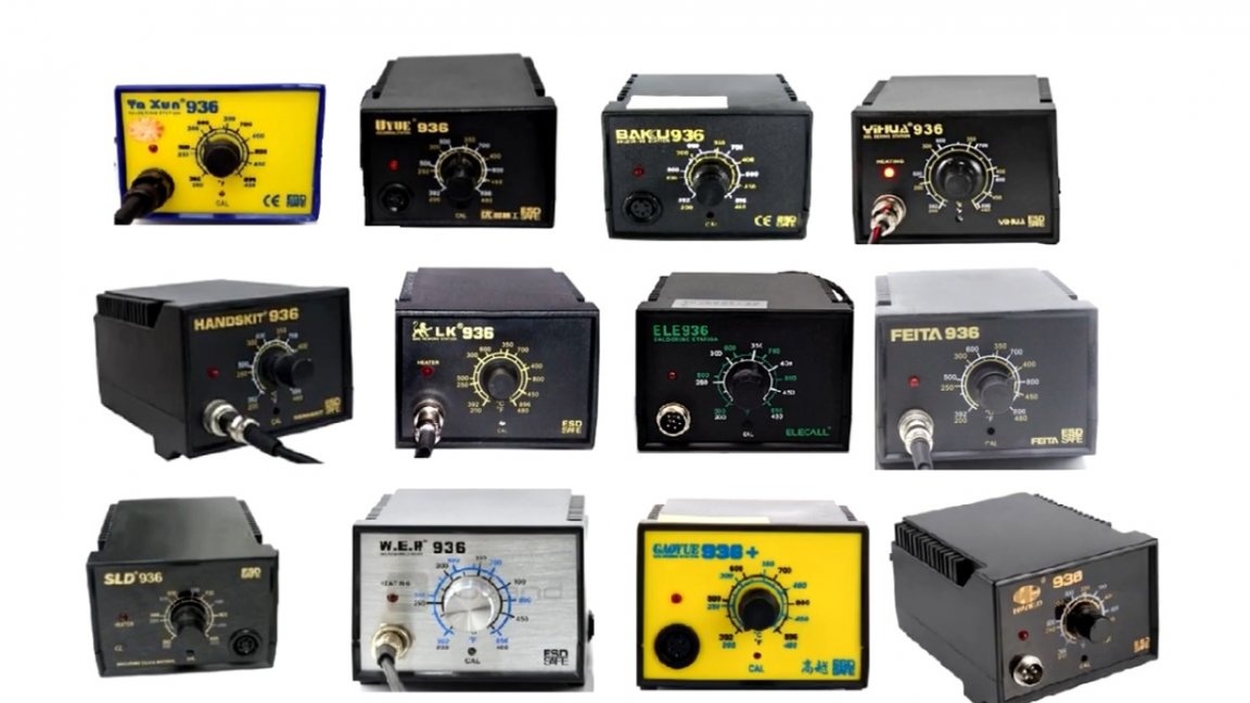
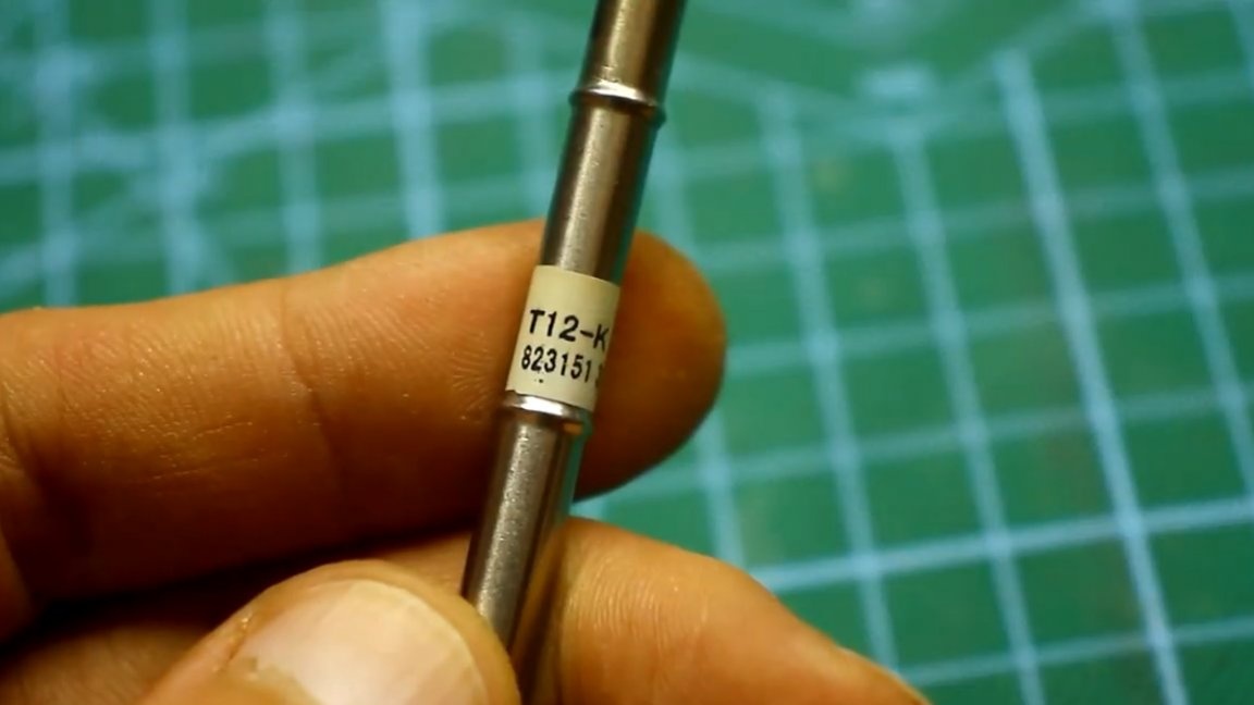
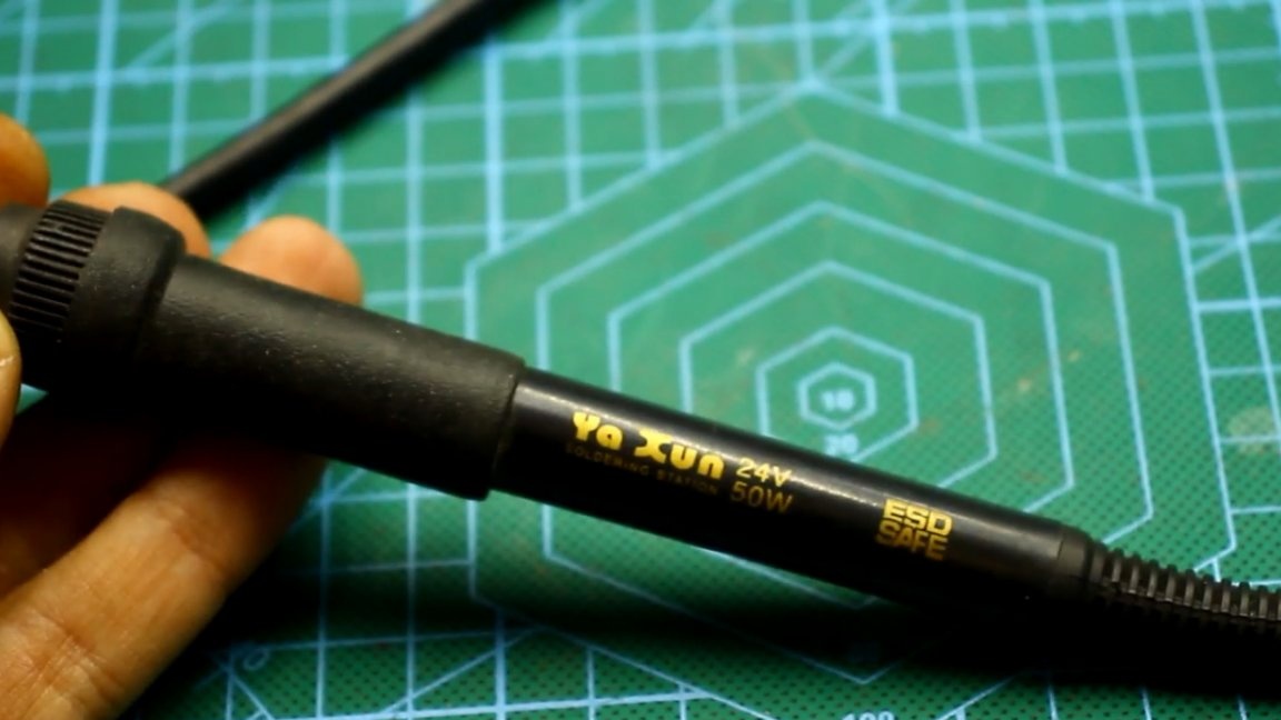
The idea of creating this project came to the author of YouTube channel “AKA KASYAN” when he understood his attic and found this
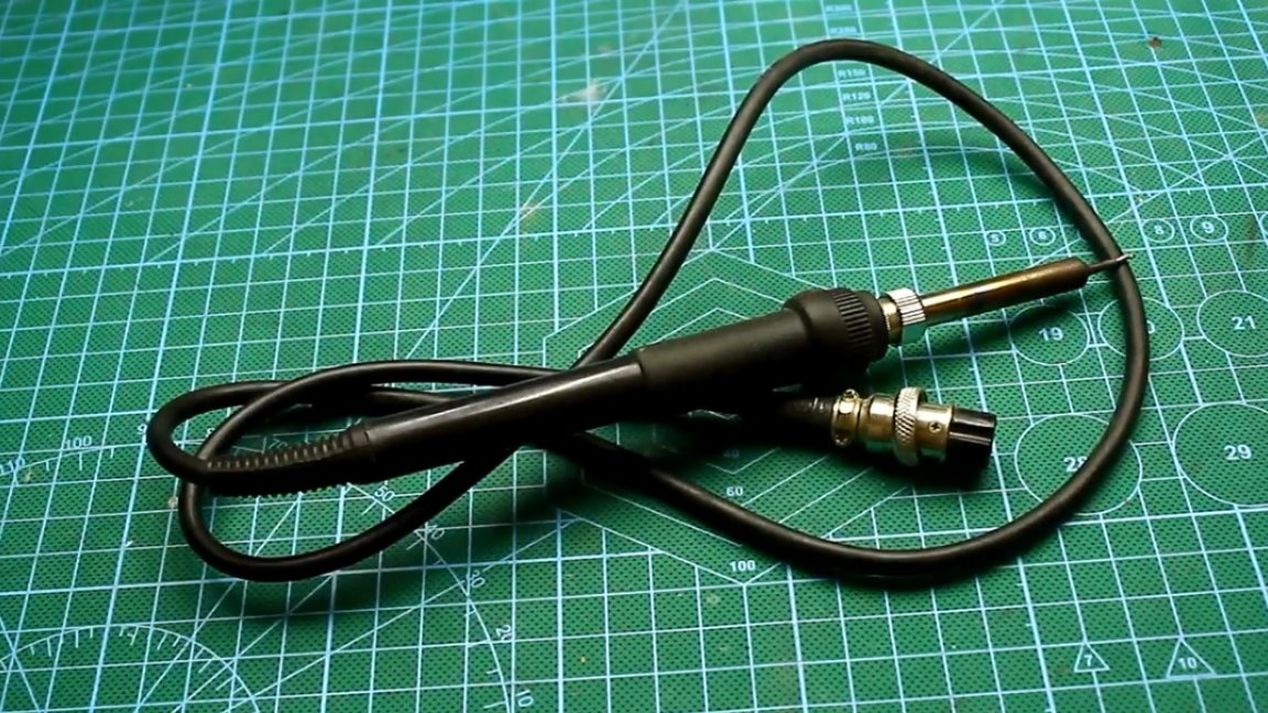
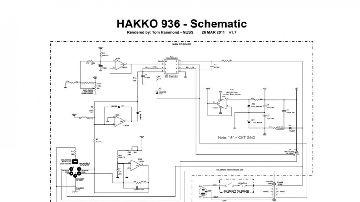
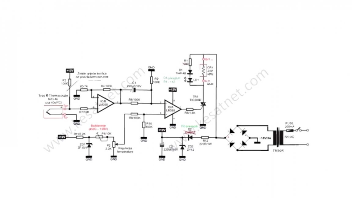
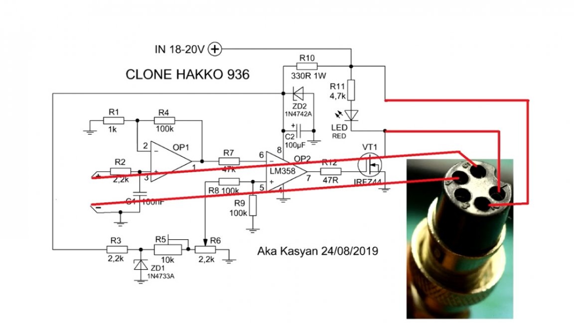
It was decided to assemble a simple soldering station and recall the past. Below is a diagram of the original Hakko 936 soldering station:
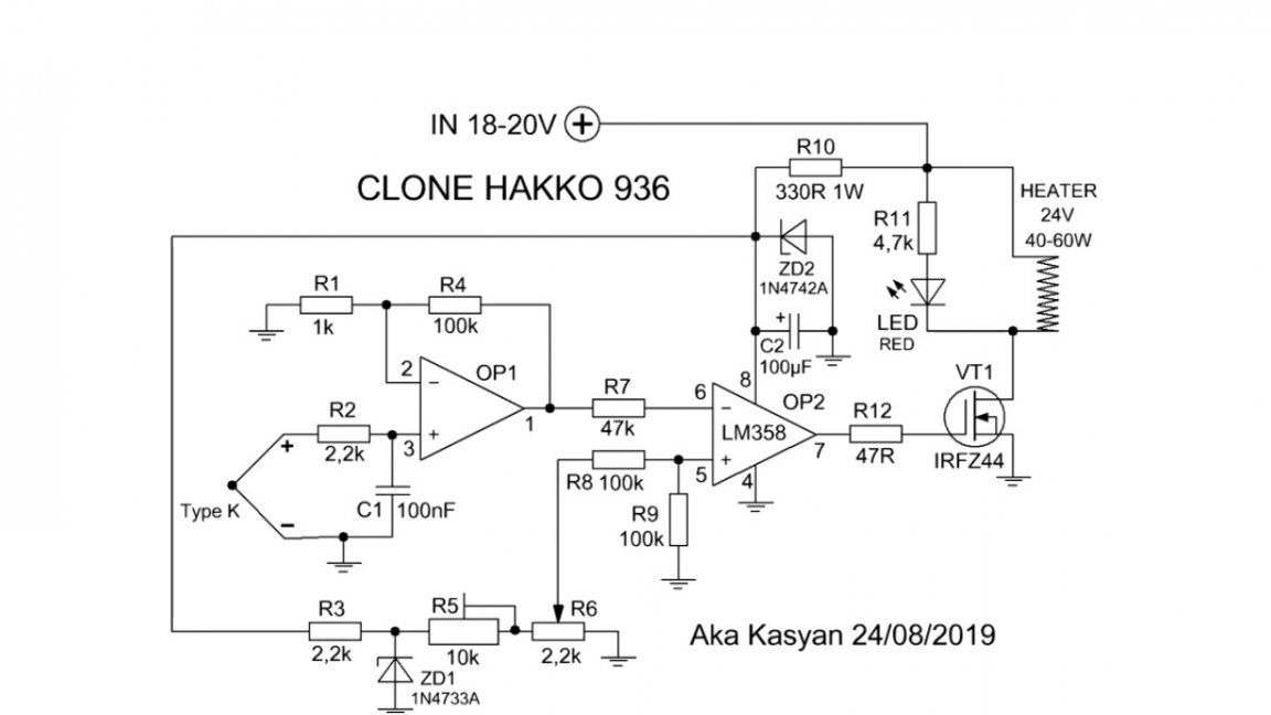
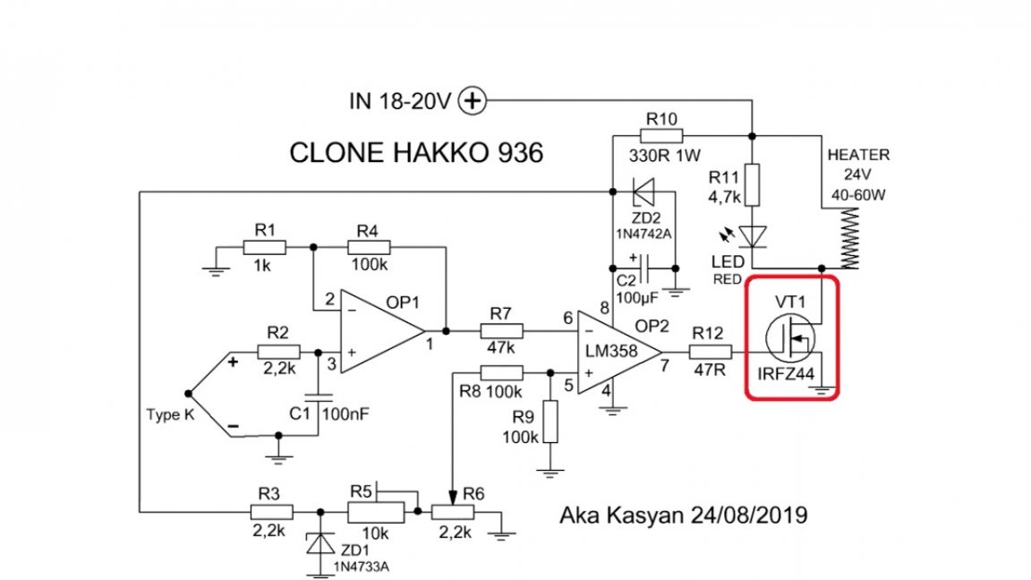
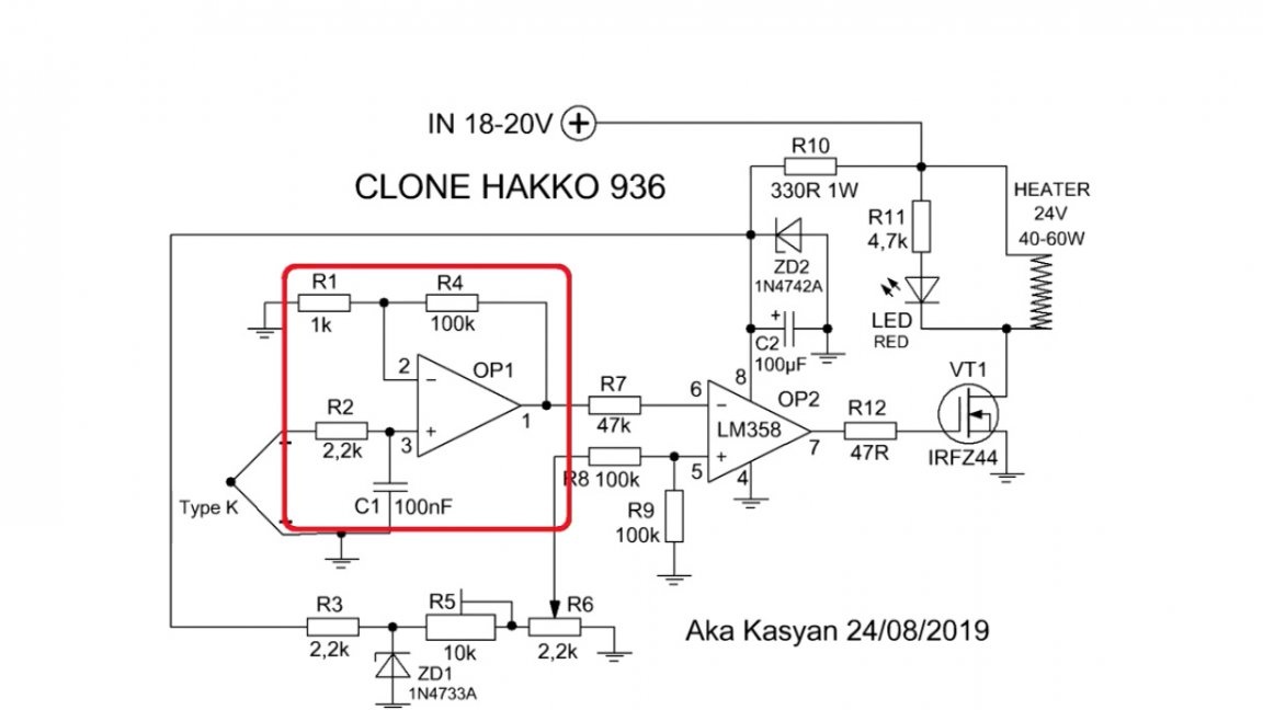
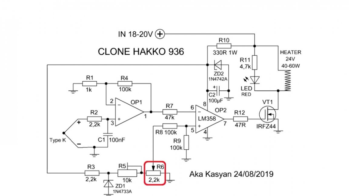
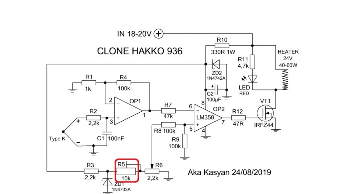
In the following image you can see a simplified diagram from Chinese clones of the same station:
The layout of Chinese clones is much simpler. The author reworked it, something you added, something diminished, thereby tailoring it to your needs.
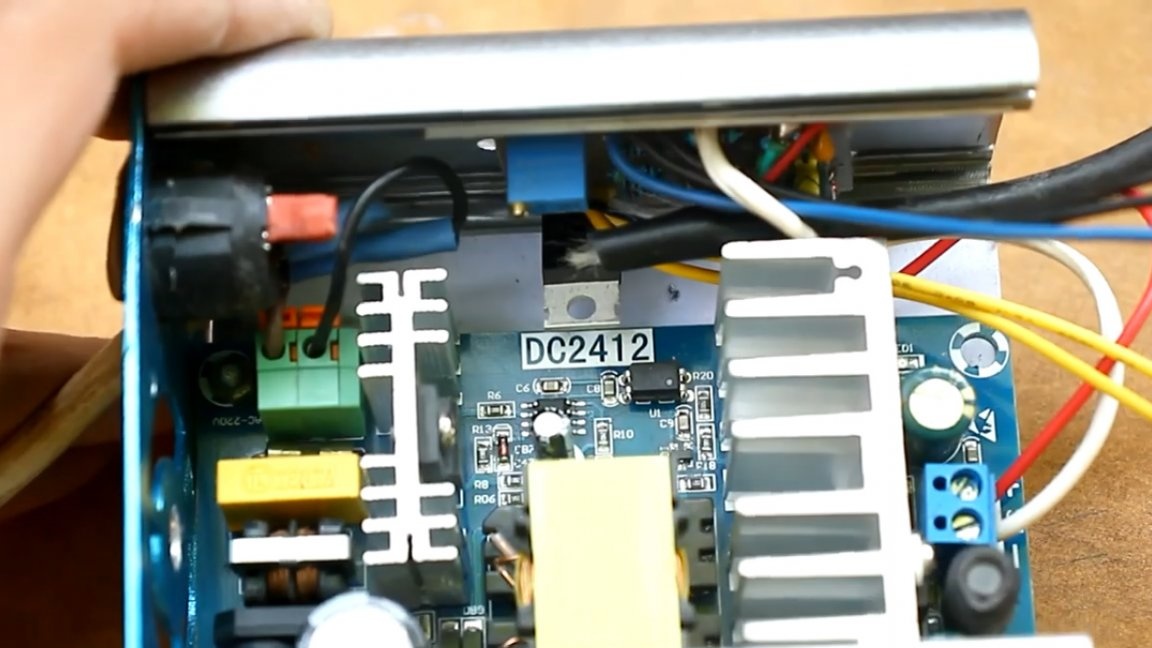
The control link in the original circuit, as you see, is the triac:
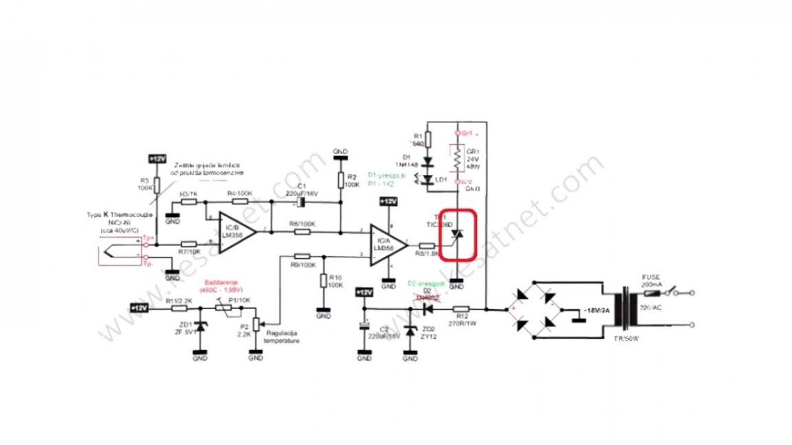
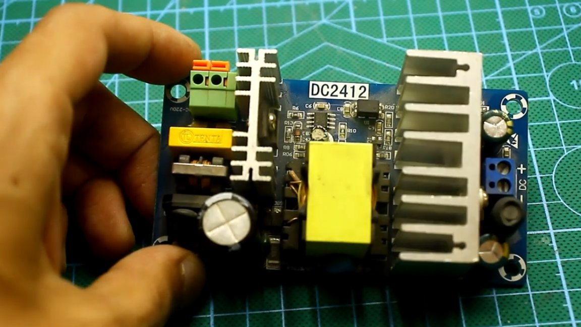
The author decided to use it in this project, and there were reasons for it, namely, as a power source, you and I will have a pulse unit with a clean output constant. In this case, the triac simply does not close, and the station will not work.
In addition, at the triac we will receive losses, they are certainly not so noticeable, but nevertheless, therefore, selected.
The station is analog, no PWM control. All controls are built on a dual operational amplifier.
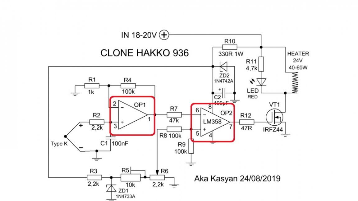
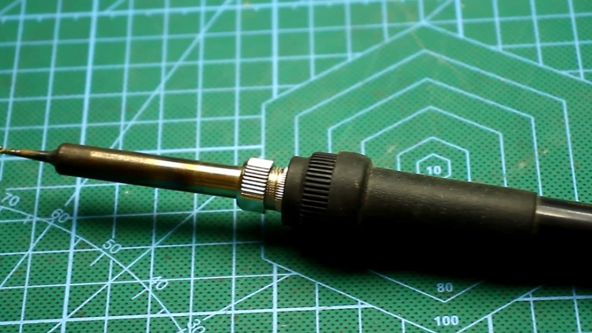
As you know, in any normal soldering iron there is a thermocouple.
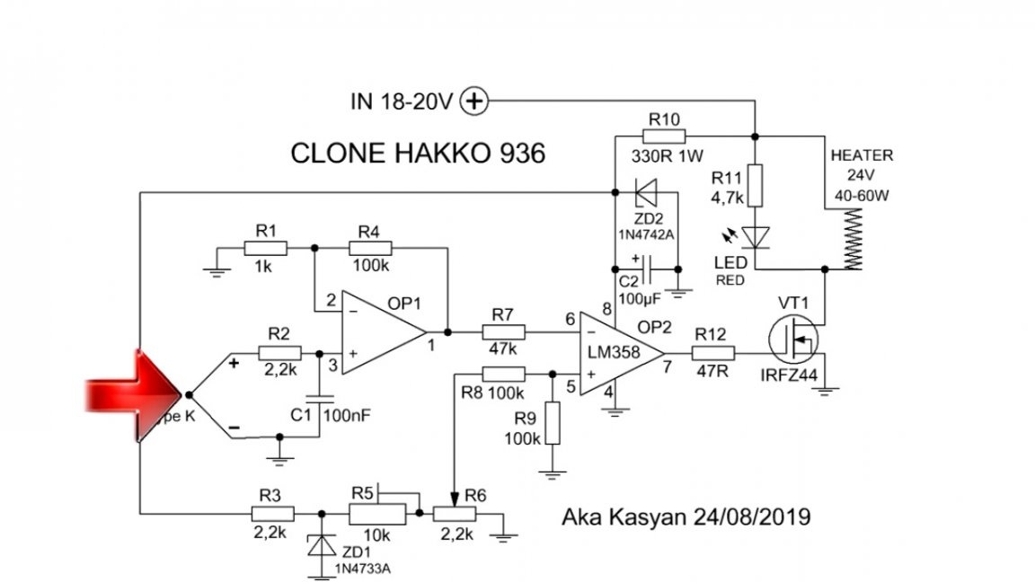
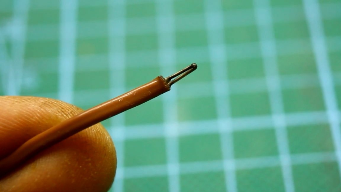
It is necessary to control the temperature of the sting. A thermocouple is two dissimilar metals welded together. The thermocouple has a ball-shaped tip, and when this ball heats up, the thermocouple generates scanty electricity.
If you connect a thermocouple to the multimeter and heat it, the voltage will be only 12mV.
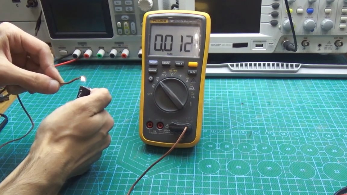
This is not enough to use a thermocouple in a real circuit. This voltage must be increased, and therefore the first part of the circuit is a voltage amplifier with a thermocouple.
For clarity, we will carry out the same experiment, but with an amplifier:
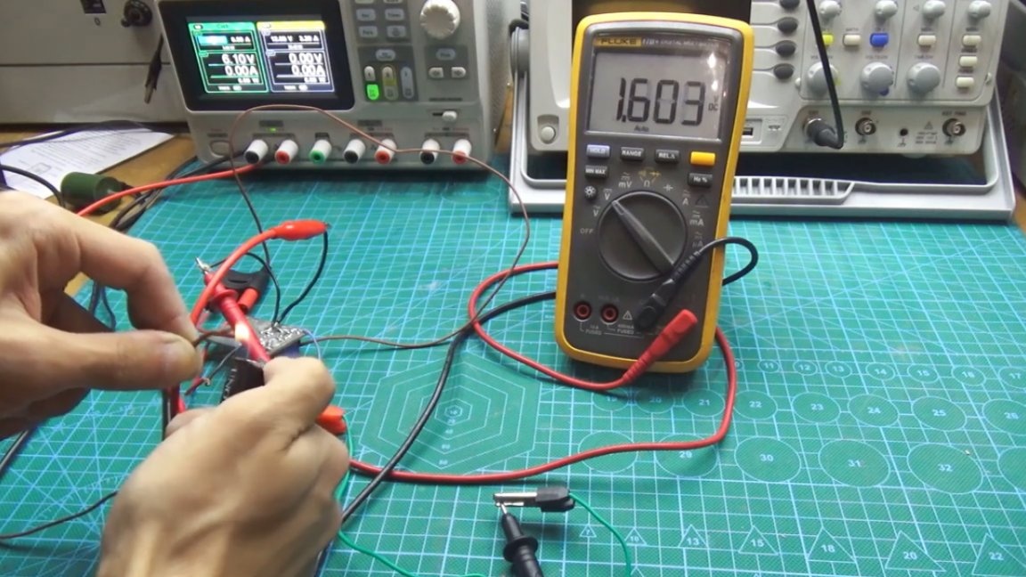
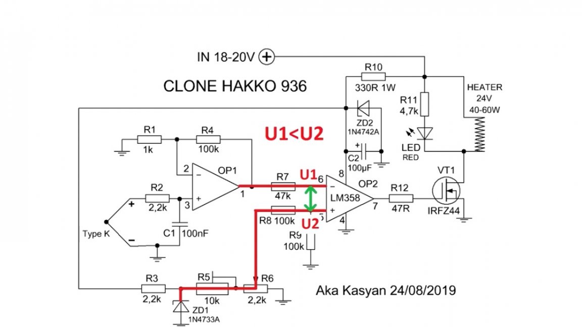
As you can see, the voltage on the multimeter reaches 1.5V. Then the amplified voltage is supplied to the inverse input of the second element.
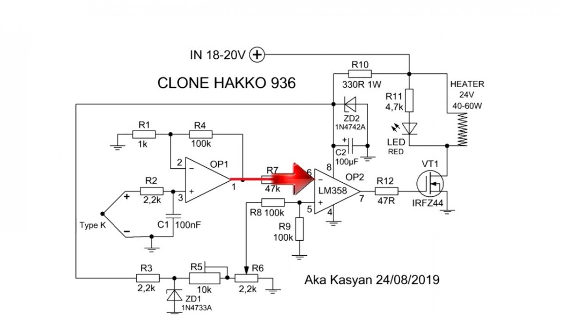
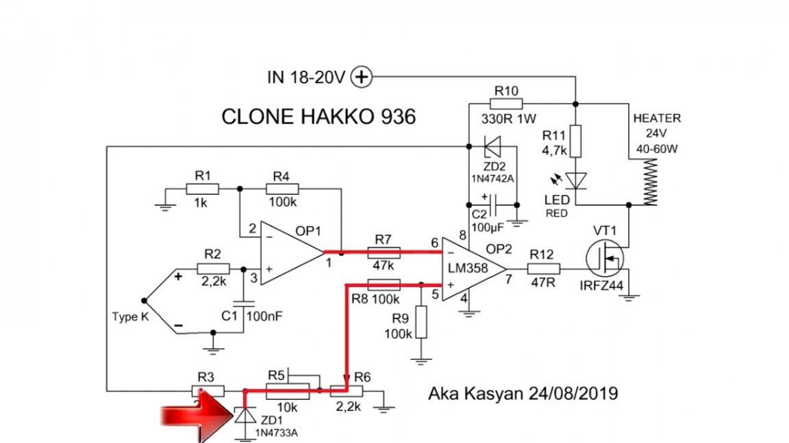
At its non-inverting input, voltage is supplied from a reference source, which is formed by a 5.1V zener diode.
Further, the voltage from the thermocouple is compared with the reference one, and if the voltage that comes from the thermocouple is lower than the reference voltage, then at the output of the operational amplifier we get a unit (1) or plus (+) of power and vice versa.
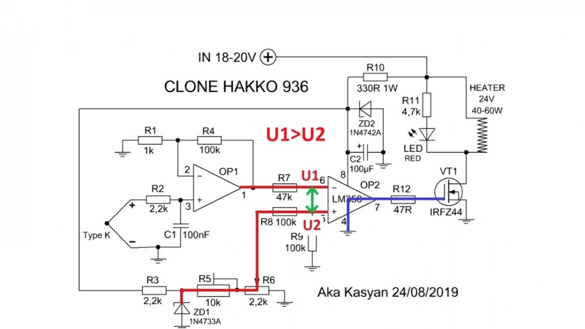
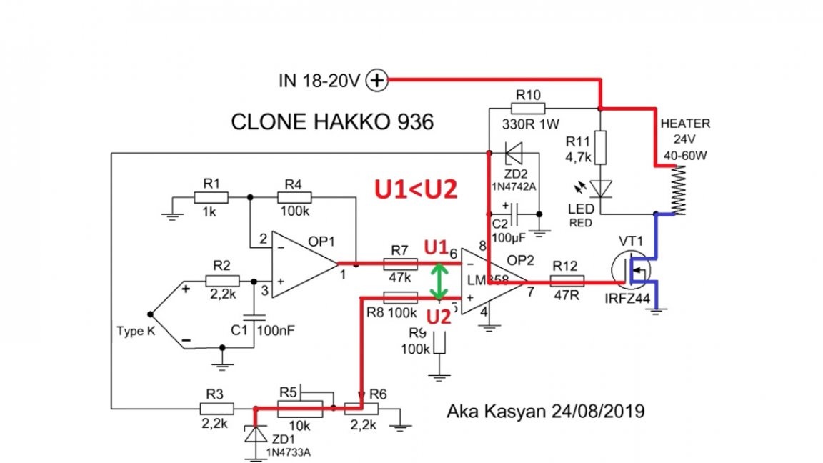
A soldering iron heating element and an LED, which acts as an indicator, are connected to the drain circuit of the transistor.
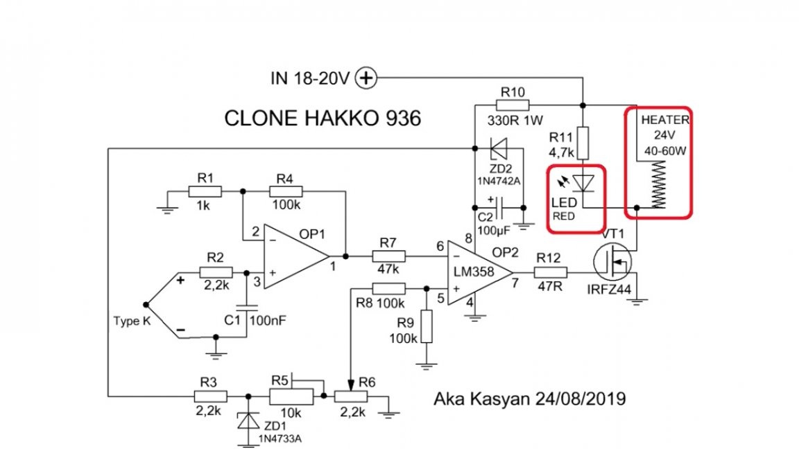
If the LED is lit, this indicates a heating tip. During operation, it will turn on and off periodically, that is, if the thermocouple is cold, the transistor turns on and heating starts, and when the heater, and, therefore, the thermocouple is heated to the set temperature, the transistor closes and heating stops, and so on all the time.
You can adjust the temperature using a variable resistor.
Basically, such soldering irons operate on 24V, and sometimes a little less.
To power the control circuit in the face of an operational amplifier, the voltage is reduced to 12V using a second zener diode.
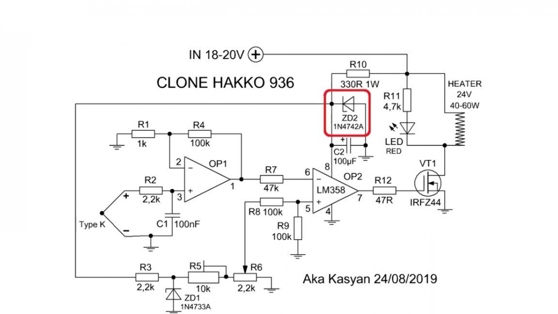
Of course, you can use microcircuit stabilizers on 12V, but the operational amplifier consumes scanty current and the usual 1W zener diode is enough.
It is possible to completely manage with just one zener diode, take the reference voltage directly from the voltage supplying the operative, but in this case, many components of the circuit will have to be counted, and besides, it is more preferable to have a separate reference source.
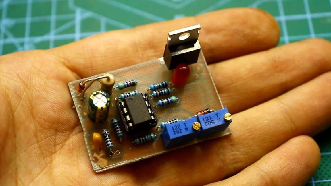
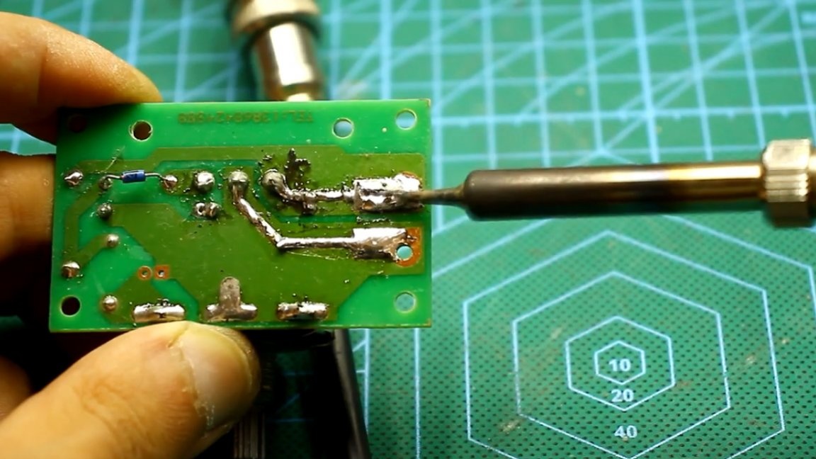
Here is such a compact printed circuit board turned out:
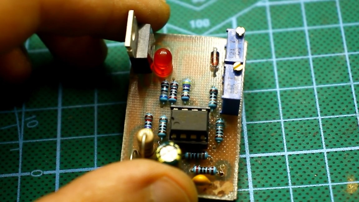
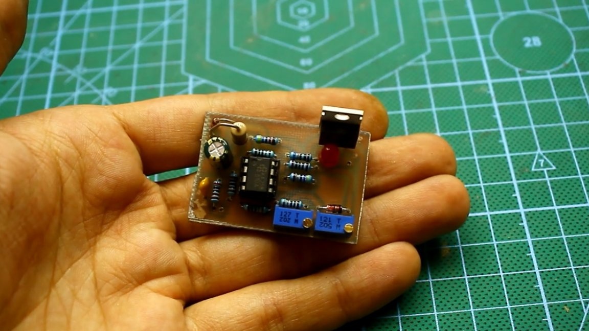
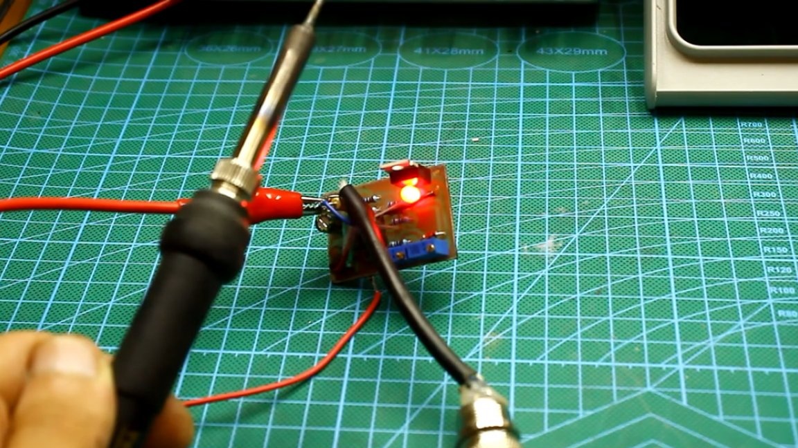
Her you can download together with the general archive of the project. Now let's check the operation of the circuit. The image below shows the pinout of the connector used in this soldering iron project:
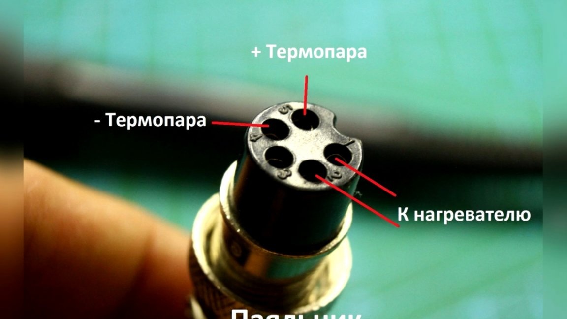
Next, we connect everything according to the scheme. The heater does not have a polarity, but the thermocouple - yes, and if the thermocouple is connected incorrectly, the circuit will not respond to heating and the transistor will be open all the time.
After connecting, it is necessary to calibrate the temperature of the soldering iron tip. Especially for this task, a trimmer resistor is provided on the board.
For more details on the process of assembling, tuning and calibrating a homemade soldering station, see the original Author’s video:
Slow rotation of the tuning resistor we need to achieve the desired temperature. The maximum temperature for such soldering stations, as a rule, lies in the range from 420 to 480 degrees.
So, the calibration is complete. Next, everything must be installed in the housing.
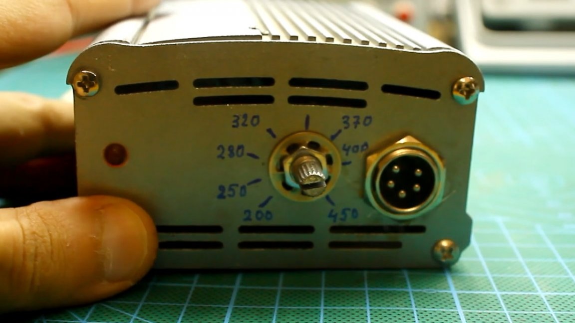
Now we are going to make an analogue scale. To do this, first put the regulator in the minimum position, wait for maximum heating, and measure the temperature. The resulting value is applied to the scale.
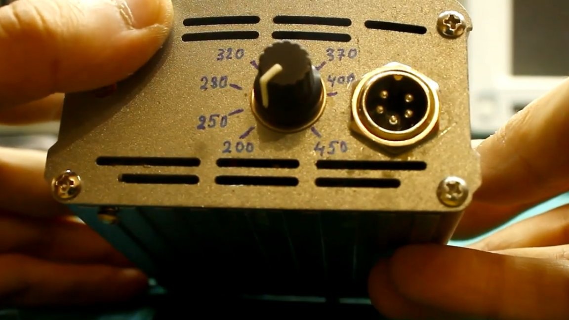
Next, we do the same for different temperatures: 250 degrees, 280, 300, 320, 350, and so on up to 480 degrees.
After the done manipulations, we got a clone of the Nakko 936 station mentioned at the beginning of the article. Everything works exactly the same way there.
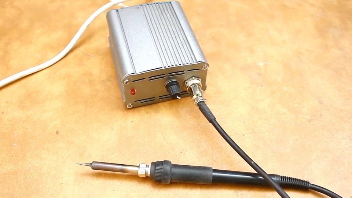
In order to see the heating process in real time, the indicator LED must be displayed on the front panel.
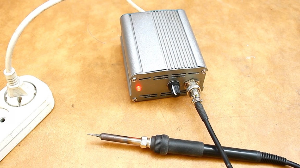
Here is a soldering station in the end we did. That's all. Thank you for attention. See you soon!