» Topics » Advice »Distributor of audio and video signals

Distributor of audio and video signals


Hello, dear authors, journalists, readers!

My homemade may be useful to those involved in audio, video and other signals.


It may be necessary to send an audio or video signal from one source to several consumers simultaneously, over a long distance, without distortion and interference, and through poor wires and cables.

For those who want to repeat this product, I will say. Basic knowledge, a minimum of instruments and tools are required.

The author, in the development and manufacture, applied the following:

Frequency counter electron-counting RFZ – 07–002
Oscilloscope S1-73
Laboratory power supply unit MARS
The device of the telemaster LASPI-TT-01
Functional generator L30
Multimeter M890G
Avometer Ts20
SAMSUNG VCR ELECTRONICS BM1230
TV sets RECORD, SANYO, TELEFUNKEN
Musical centers JVS, PANASONIC, AIWA.
Resistor Set
Cords, cables, wires. RK-75, TRP, KSPV.
Soldering irons are different.
Solder, ferric chloride, rosin, solvent, glue.
The tools are different.

Let's start with the concept.


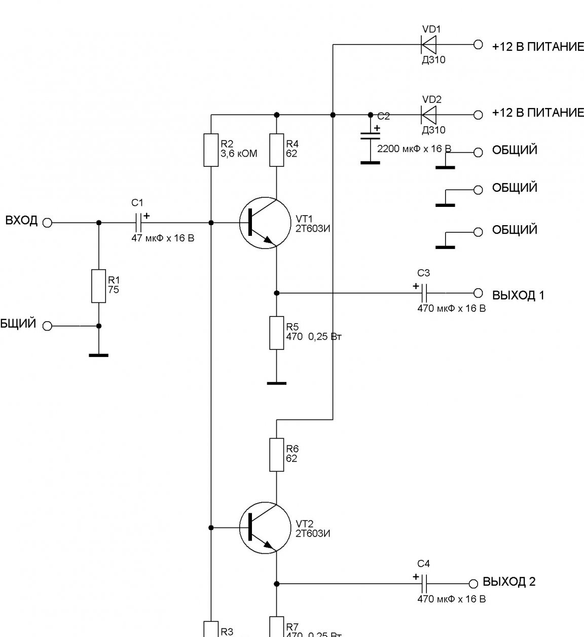
I laid the basis for its important properties of the so-called emitter follower ..

It does not amplify the voltage signal, it even weakens negligibly, by 1 - 2 percent.

But, amplifies the current and power.

In addition, it has a low output impedance.

Regarding the output resistance of the emitter follower. Do not think that it is equal to the resistance in the emitter of the transistor. It is determined by many factors, for example, the gain of the transistor, the current through it.

An output impedance of less than one ohm can be achieved.

However, it is almost impossible to calculate all the parameters, I selected empirically.

Not prone to self-excitation.

With regards to self-excitation. The gain of the emitter follower is slightly less than unity, and for generation to occur, positive feedback with a coefficient greater than unity is needed.

Good frequency response.

Regarding the frequency response. It is characteristic of cascades with low gain.

As a result, we get this.

Successfully distributing a broadband signal to several consumers. Suppress interference and interference on long lines with low output impedance.

So (on the example of a video signal).

The signal comes, for example, from a DVD player to the terminating resistor R1. Its resistance is 75 ohms (accepted for video signals). Through the isolation capacitor C1, the signal is supplied to the bases of two high-frequency transistors VT1 and VT2, connected according to the emitter follower circuit.This circuit is also called the common collector, OK. Do not confuse with an open collector, also OK.

I chose transistors 2T603 according to the following criteria. High frequency, sufficient current transfer coefficient, sufficient power dissipation.

The offset at their bases is specified by the divisor R2 R3. The application of the OK circuit allowed us to combine the base of transistors and reduce the number of circuit elements.

The emitter loads are resistors R5 and R7.

Resistors R4 and R6 in the collector circuit of the transistors are current limiters.

From the loads through the capacitors C3 and C4, the signals are sent to consumers. In this scheme, at least two consumers (TV) can be connected to each output. In practice, more.

About nutrition:

In this version, I made two power inputs for extra reliability.

For this, diodes VD1 and VD2 are used. They also serve to protect against power surges.

It looks like this .. If one power supply fails, one of the diodes is locked and does not allow the working unit to direct power to a non-working one. The same thing, with the addition, the diode is locked and does not allow the voltage of reverse polarity to get on the circuit and disable it.

The choice fell on the D310, as they have a small voltage drop and are designed with a margin for the current consumed by the device.
Can be replaced with modern diodes (Schottky).

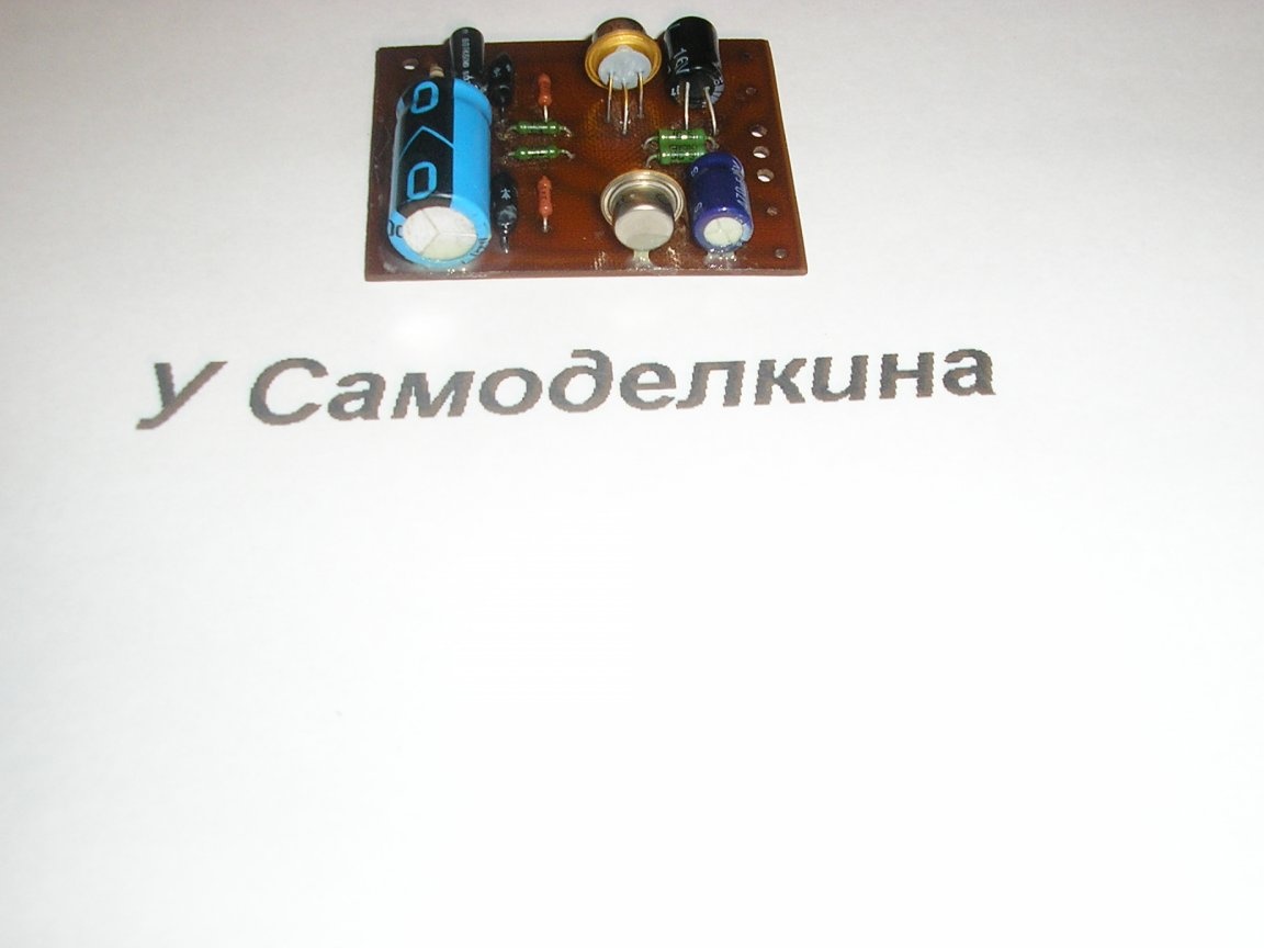
A view of the assembled circuit board is shown in the photo.


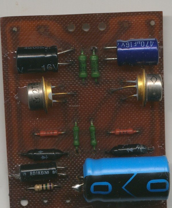
This photo shows that it turned out to be very compact. For comparison, I put a matchbox next to it.


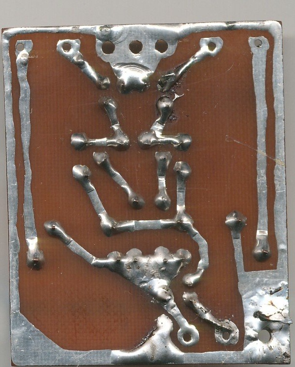
I drew this printed circuit board by hand, the tracks are not as beautiful as they should be. But, I considered it fair to show. It is even more obvious that I bred it without a computer, but all the details are beautifully and optimally arranged and there are at least tracks, no jumpers.


Now for the details.

Here is the pinout of the applied transistors.


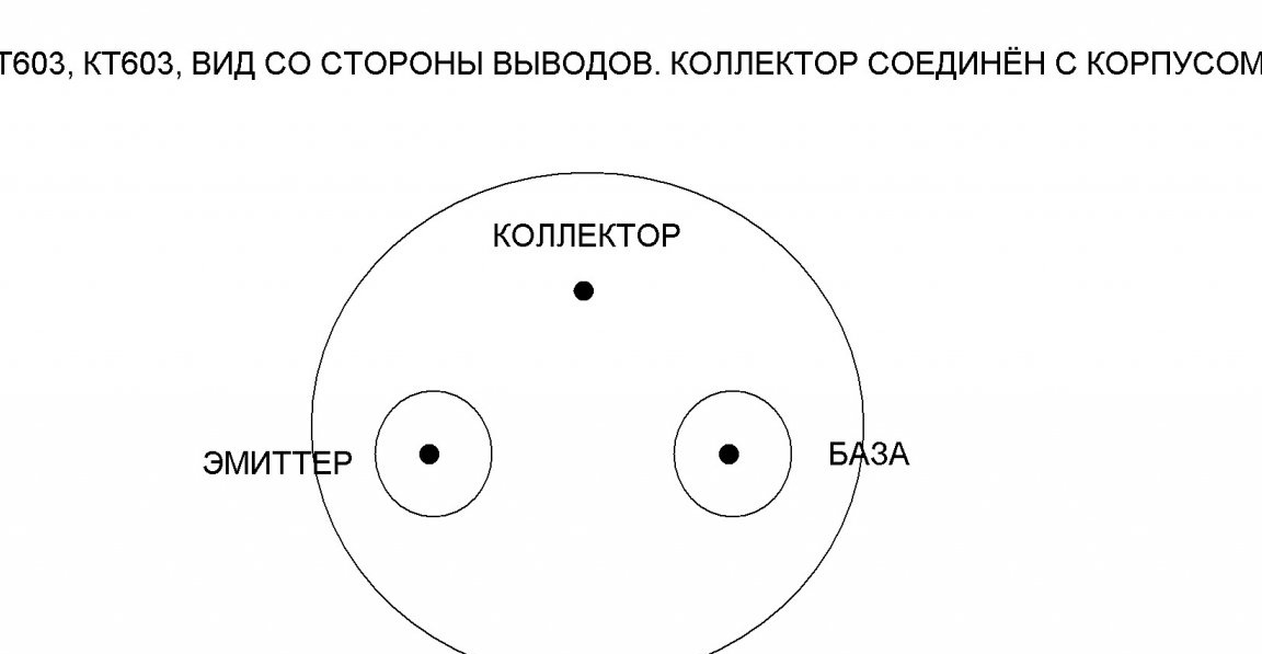
Of course, it is not necessary to use 2T603I, any KT603 will go, the final letter is not so important.

Moreover, the KT646B and KT972A will work, in my opinion their conclusions will fit this board, they just have flat cases, not round ones.

Now, if you transmit sound.

The input resistor R1 must be increased to 10 kOhm (accepted for audio signals). The number of consumers by sound will be dozens. All capacitor capacities, except those in the power filter, can be reduced by a factor of ten.

By video and sound.

It must be understood that if we want to transmit S video or component video, the number of such boards must be increased according to the number of channels.

The same thing, if the sound is stereo, then you need two boards.

Want to add. This system allows you to transmit and pulse signals.

You, of course, have a question, but how can this be avoided by interference? The low output impedance of the emitter follower does not allow them to visit. And your signal goes perfectly in line.

I have another similar homemade product. Next time I will present it to your attention.

There are fewer parts in it, for example, a transistor is only one and the output is only one. However, much more consumers can be connected to it.

I hope my article will be useful to you.

Sincerely, author.

Suitable for topic

Related topics

Add a comment

    • smilesmilesxaxaokdontknowyahoonea
      bossscratchfoolyesyes-yesaggressivesecret
      sorrydancedance2dance3pardonhelpdrinks
      stopfriendsgoodgoodgoodwhistleswoontongue
      smokeclappingcraydeclarederisivedon-t_mentiondownload
      heatirefullaugh1mdameetingmoskingnegative
      not_ipopcornpunishreadscarescaressearch
      tauntthank_youthisto_clueumnikacuteagree
      badbeeeblack_eyeblum3blushboastboredom
      censoredpleasantrysecret2threatenvictoryyusun_bespectacled
      shokrespektlolprevedwelcomekrutoyya_za
      ya_dobryihelperne_huliganne_othodifludbanclose
30 comments
Guest Alex
It was the year 1975 ...
This year I entered the institute, before the advent of the Internet, we had some 20 years left! We searched for replacements for radio components by analyzing and comparing their characteristics in reference books, which then were not so easy to get!
Guest Alex
It was the year 1975 ...
Do you offer to steal details from the museum or what?
Quote: R555
Yes, open transistor, mode A, base current.

Do not intervene if you do not understand what is at stake.
If the transistor is open, then Re will have a full supply voltage.
Author
Ivan_Pokhmelev! I read about the multicomponent interference, as well as the additive one, with which it adds up and multiplies. In short, multi - remotes. I wrote here that I am collecting a special surge protector for my apartment. Your tip (indication) will help me with this. Thanks. Then I will publish it as an author.
Author
Ivan_Pokhmelev! Yes, open transistor, mode A, base current. I had no doubt that you would filter the opponent off.
R555
Quote: Nruter
The transistor operates in mode A, i.e. located exactly in the middle of the characteristics.
What characteristics?
Quote: Nruter
The current flows through the circuit + U - Rк - open transistor - Re - -U.
It's hard not to agree.))
Quote: Nruter
And where do you throw Rk from this chain?
I don’t throw it out of this chain. Why do you think so? It just is not needed for calculating IE. I allow myself to quote you:
Quote: Nruter
Therefore, the voltage on its emitter should be equal to half the voltage of the power source, i.e. Ue = 6 V.
It follows, if not argue with Uncle Zhora yes such that Ie = Ue / Re.
Quote: Nruter
This is a microshow base current in low-power transistors, which can be ignored. And in powerful cascades it is significant.
It does not matter if the current is large or small. The current gain h21e is important. Again, I will quote you:
Quote: Nruter
(we will accept for calculation 25)
This means that the emitter current is 4% more than the collector current than can be neglected for rough calculations. If you really, really want to, you can slightly correct the Uke calculation formula, but for the available denominations the difference will be less than a percent.
And finally, usually low-power transistors have more h21e than powerful, but not always. For example, for many old low-power transistors, β is small, and, for example, for KT863A it is more than 100.
Quote: Ivan_Pokhmelev
add to Rе Rк - fundamentally wrong.

The transistor operates in mode A, i.e. located exactly in the middle of the characteristics. The current flows through the circuit + U - Rк - open transistor - Re - -U. And where do you throw Rk from this chain? Its function is to limit the collector current.
This is a microshow base current in low-power transistors, which can be ignored. And in powerful cascades it is significant.
Author
Ivan_Pokhmelev, thanks. Yes, it’s not for nothing that I asked this question, even if you say it is not entirely correct. I decided for myself that 4 penny capacitors will not hurt. Multiplicative interference ... I read what it is, a term unfamiliar to me.
Quote: Nruter
And where did the collector current go? In a bipolar transistor, the emitter current is the sum of the collector current + base current.
In practical evaluative calculations, in most cases, the base current can be calmly neglected due to its relative smallness and the emitter current is assumed to be equal to the collector current. But to add to Rе Rк is fundamentally wrong.
Found. Today at 11:11 they asked. Well, I'm sorry, I’m not sitting on the Internet all the time. ;)
The answer will be: "The question is not posed quite correctly."
The need for this depends on which diodes and what kind of equipment. If this is a radio receiver or highly sensitive measuring equipment, then, KVM, capacitors are needed to suppress multiplicative interference from the network: the network as a huge antenna serves as a source of common mode interference. In addition, if the diodes are fast-acting, then the capacitors suppress ringing at the switching fronts.
And in any case, capacitors in addition to other means crush differential interference: pulsed surges on the mains voltage.
Quote: R555
Ivan_Pokhmelev. Today is Knowledge Day, but you have not answered my question. Why are diodes in 50 Hz rectifiers shunted by ceramic capacitors of small capacity?

Where did you ask this?
R555
You do not say that in expensive power supply diodes are special and do not interfere
That's it, I’ll say! If you remember, the shunting of the diodes dates back to the time of lamp technology, then the rectifier diodes were low-frequency, alloy, diffusion, (slowly switched)! Now the diodes are more nimble!
since you claim that everyone knows this effect, why they don’t do it?
I claimed that everyone knows this hams! Today, unfortunately, far from all who consider themselves to be amateur radio enthusiasts, such are actually, as, indeed, many other specialists, are the results of the I-USE-ovization of education! yes
Quote: Ivan_Pokhmelev
Ie = Ue / Re

And where did the collector current go? In a bipolar transistor, the emitter current is the sum of the collector current + base current. Depending on the structure, it either flows into or flows out.
Uke = Upit - Ie • (Rк + Re),

By this you confirm this.
And with the power dissipated on the collector, everything is clear :)
Korolev Not only receivers growl, but also refrigerators, as in the movie “Hottabych,” why did you break the refrigerator, he growled at me)). And those pocket receivers like “Meridian” or “Olympic” are they from the battery, but sometimes they also growl and whistle there you can see the feedback in the coils with the speaker?
Author
Korolev You are right about the interference caused by the diodes. But they are wrong in the part that every radio amateur knows this. Far, far, far from everyone and not a highly qualified engineer. I don’t ask simple riddles. And if you carefully read what I write, then I mentioned that these air conditioners are sometimes installed in the cheapest PSUs, but not expensive ones. You do not say that in expensive power supply diodes are special and do not interfere (we are talking about ordinary, non-pulse power supplies). So, since you say that everyone knows this effect, why they don’t do it? I am talking about certified equipment, equipment of well-known companies. Who is betting, who is not betting. Okay, it’s excusable for a beginner radio amateur, but when, sorry to SONY, SANYO it is not delivered. I have several such branded blocks lying around. I am now collecting a special surge protector for my apartment, there the function of suppressing this interference is laid down. And I thought. I’ll try to cut the oscilloscope to the BP diodes without ceramic capacitors. How many mV / Del will show. Stopped, it will be necessary to filter 100 Hz. I’ll do it easier. I’ll take an old VEF-202 and cut it on long waves. And the climber, I don’t remember the model I have. Nevertheless, I want to find out how strong these obstacles are in reality. I am familiar with thyristors, triacs in this part - horror.
R555
Why are diodes in 50 Hz rectifiers shunted by ceramic capacitors of small capacity?
I apologize, the question is not for me, but any radio fan thinks this is known!
And they are needed to suppress high-frequency interference arising from the sharp locking of the bridge diodes. So that a nearby receiver does not growl at a frequency of 100 Hz.
smile
Author
Ivan_Pokhmelev. The question is why do diodes in rectifiers bypass with ceramic capacitors? In the photo I showed the secondary winding of a burned-out Chinese transformer. It can be seen that each bridge diode is shunted by ceramics. And I put a matchbox to establish my authorship. The falcon on the fire arrow will indicate this. You saw this box in my extreme author's homemade product about the distributor of audio and video. By the way, I didn’t put that photo as the main one for homemade work. Apparently, the admins smiled, they pinned. The next photo goes with the inscription, as it should be bgm.imdmyself.com, I put it first in the text of the article.
Author
Ivan_Pokhmelev. Today is Knowledge Day, but you have not answered my question. Why are diodes in 50 Hz rectifiers shunted by ceramic capacitors of small capacity? You can meet this in the cheapest PSU and expensive. But not often. I said, I have a version. And you ?
Has anything changed in Ohm's law over the past 15 years?
Quote: Nruter
Quiescent current Ie = Ue / (Rк + Re)
Ie = Ue / Re, Uke = Upit - Ie • (Rк + Re), Pras = Ie • Uke
Regarding the frequency response. It is characteristic of cascades with low gain.
Frequency characteristics (frequency response, phase response) are characteristic in general any electrical circuits. )))
Guest Alex
This scheme was relevant 10-15 years ago. Why is it now? Because of nostalgia?
Author
Oh, by the way, we just take it, replace KT603I with KT972A, which I wrote about in the article, and they have 750 gain! This is a composite and fairly high-frequency transistor. We throw out the limiting resistor from the collector, reduce the emitter to 100 Ohms. A second transistor and circuit are not needed. Will you raise the white flag? Joke.
Quote: R555
There is a question on resistors in the emitter

There is. It needs to be increased by a factor of 10. Everything will benefit from this. The input impedance of the circuit will increase, which will positively affect the load capacity of the cascade.
Accordingly, the values ​​of the resistors of the base divider will change. And it is advisable to use transistors with a larger coefficient.
Author
You are a competent person, it is interesting to butt you. In fact, you recognized that only one output of my circuit provides good load capacity. And there are two exits. You are attached to the wrong calculation of the voltage divider common to two transistors. I now fluently re-scanned for a minimum gain of these transistors 20. Well, a little squanders on emitters. It will not affect the work. That's when the emitters will be volt 2, then yes. We can just slightly reduce the R2 resistance. Is there a question on collector dissipation? Not. Is there a question on frequency? Not. Right. For resistors in the emitter, the question is No. Right. They noticed that I even indicated their power 0, 25 W, the rest did not regulate. What other claims will be? Maybe all the same recommendations for improvement?
That is, the correctness of the scheme does not bother you at all?
Author
Please, a reference to my theft of other people's schemes. Show the circuit with which I sketched.
Quote: R555
If you read carefully

I read it carefully.
One repeater is enough for 5-10 devices.
Quote: R555
And here the transistor gain and quiescent current

Moreover. The input impedance of the cascade is Rin = Kus * Re. In our case, Kus = 20 .... 30, Re = 470 Ohm. Rin = 9.4 ... 14.1 kOhm. Not very good.
The repeater should operate in mode A. Therefore, the voltage on its emitter should be equal to half the voltage of the power source, i.e. Ue = 6 V.
Quiescent current Ie = Ue / (Rк + Re) = 6 / (62 + 470) = 11 mA. Power dissipated by the transistor P = 6 * 11 = 66 mW.
Now we determine the base current. Given Kus = Ik / Ib, we get Ib = 11 / (20 ... 30) (we will take 25 for calculation). The base current is 440 μA. The current of the base divider is taken more than the base current every 10 times. Total, 4.4 mA.
For normal operation of the transistor, the voltage at its base should be higher than the voltage at the emitter by 0.55-0.6 V. We will take 0.6 V. Therefore, Ub = 6.6 V. Since the divider current is 4.4 mA, and the voltage is Ub = 6, 6 V, then Rbe = 6.6 / 4.4 = 1.5 kOhm. At the second resistor of the divider Rb, the voltage drops 12-6.6 = 5.4 V. Hence, Rb = 5.4 / 4.4 = 1.2 kOhm.
Given that for some reason you connected two transistors in parallel along the base circuit, the resistance of these resistors must be reduced by half. And you have much more.
In conclusion, a small remark. No need to give out other people's schemes (with errors) for their own development.
Author
I explain. If you carefully read my article, it is clearly written there that this board is designed strictly for one channel of whatever. Audio, video, number. Further. And here the amplification of the transistor and the quiescent current. I specifically made such a quiescent current so that the bottoms of the video sync pulses are not cut. Do you really think that in the list of equipment for the sake of fun I named the brands of Vidak, TV sets, with what this scheme was checked?
Further. Why 2 transistors. To enhance the output parameters. And further. If you read my article very carefully, it says that I have long ago created a more powerful circuit with fewer details on just one transistor.All this is tested in practice. I got paid. Let us discuss this homemade product for now.
The choice of KT603I is simply perplexing. This transistor has a current gain of 20 to 50. Therefore, the quiescent current is very large (about 20 mA). If done correctly, then on one board there should be at least 3 repeaters - for video and for stereo sound.
Why are two repeaters connected in parallel in the circuit?

We advise you to read:

Hand it for the smartphone ...