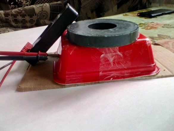
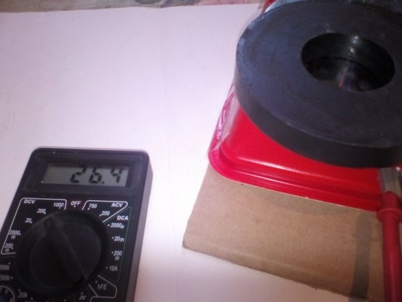
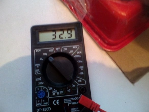
How it will work: the generator will convert the mechanical energy of the hand into electrical energy. All this is based on the phenomenon of electromagnetic induction, which I think does not need to be explained.
Materials and Tools
1 Cheap electromagnet for 70 rubles. Purchased on the radio market (you can reel yourself)
2 dvd drive
3 permanent magnet (in my case from the speaker)
4 plastic container for instant noodles (better not used)
5 insulating wire 3 colors
6 adhesive tape
7 cardboard
8 soldering iron (if desired, and skill is possible without it)
9 glue gun
10 soldering acid or rosin
11 solder
12 diodes 4 pcs.
13 capacitor at 400 to 150 uF
14 multimeter
Description of the creation of the device.
After we figured out what kind of device it is and for what purposes we proceed to describe the assembly.
1st step (Diode bridge)
A diode bridge is a bridge circuit for connecting diodes to rectify AC to DC.
Diode bridges are the simplest and most common rectifiers, they are used in radio engineering, electronics, cars and other areas where pulsed DC voltage is required.
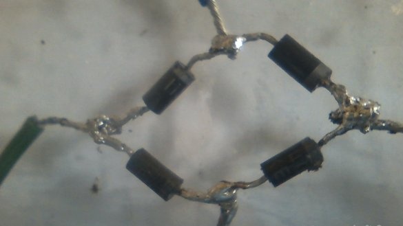
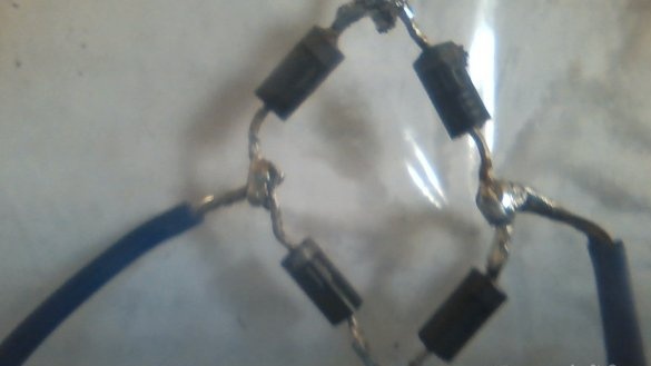
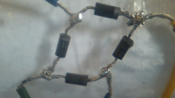
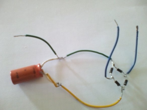
We take diodes first tin them and solder them according to this scheme
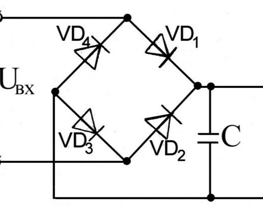
Next, we cut off two insulated wires in my case, these are blue and a couple of yellow and green (which could be different cases at your fingertips).
Blue wires are tinned and soldered between diode 4 and 1, 3 and 2.
And green between 4 and 3 diodes is a minus, and yellow between 1 and 2 diodes is a plus.
A few words about how the diode bridge works. If an alternating current is applied to its input, the polarity of which changes with a certain frequency, then at the output (terminals “+” and “-”) we get a current of exactly the same polarity. True, this current will have ripple. Their frequency will be twice as much as the frequency of the alternating current that is supplied to the input.
Thus, if an alternating current of the power supply network (frequency of 70 hertz) is applied to the input of the diode bridge, then at the output we obtain a direct current with ripples of a frequency of 140 hertz. These ripples are undesirable and can greatly interfere with the operation of the electronic circuit.
To remove the ripple you need a filter. The simplest filter is an electrolytic capacitor of a sufficiently large capacity. In my case, this is a capacitor taken from an energy-saving lamp at 400V and 150uF.
To it we solder the green and yellow wire which are soldered to the minus and plus of the diode bridge.
And then we take away from the capacitor even through the yellow and green wire. It should work like this.
2nd step
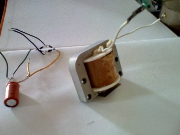
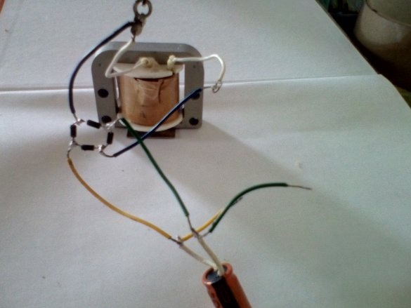
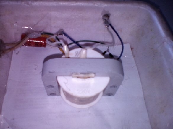
Now we take an electromagnet and a diode bridge
we attach the electromagnet to the blue wires that come from the diode bridge.
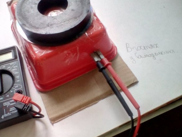
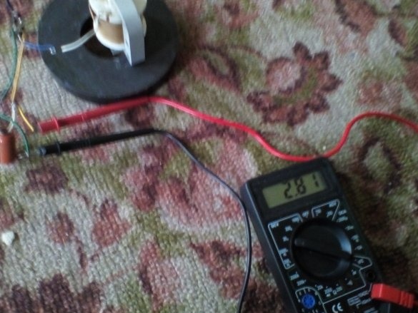
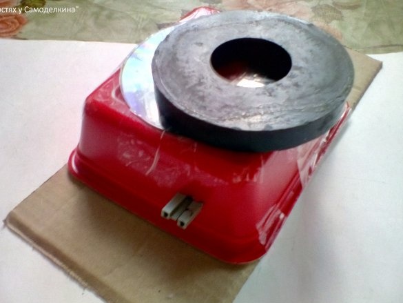
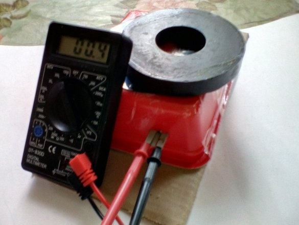
At this point, you need to check for performance. You need to connect a multimeter to the output; if it is not there, you can take an LED or a motor. We take a magnet, put our unfinished generator on the magnet and look at the screen of the multimeter if there is an electric voltage.
Apparently there is, but not much, when the generator is fully assembled it will be much larger.
3rd step (making the case)
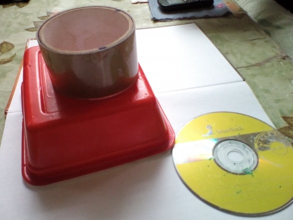
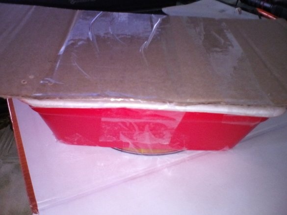
To make the case we need a container of instant noodles, dvd disk, scotch tape.
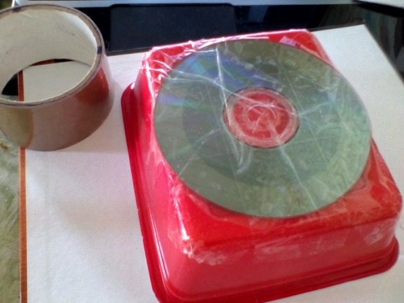
First, we turn the container upside down, but the bottom surface of the container is not even, which will adversely affect the speed of the magnet, thereby reducing the voltage.
But this can be solved by gluing a dvd disk onto tape as in the photo.
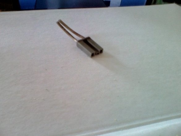
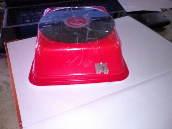
Now you need to make a cut on the small edge of the container to the size of the connector to which the multimeter or load will be connected (if there is no connector, make 2 holes, and through them output wires from the "insides" of the generator ") in my case, the connector is like this.
The connector can be sealed on the back side for structural strength.
4th step (Assembly)
Now you need to fix the connector with the "insides" of the generator.
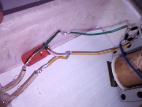
Now you need to isolate the bare spots, that is, the weld spots (insulation can be adhesive tape or heat shrink) and fasten to the walls of the radio component.
[center]
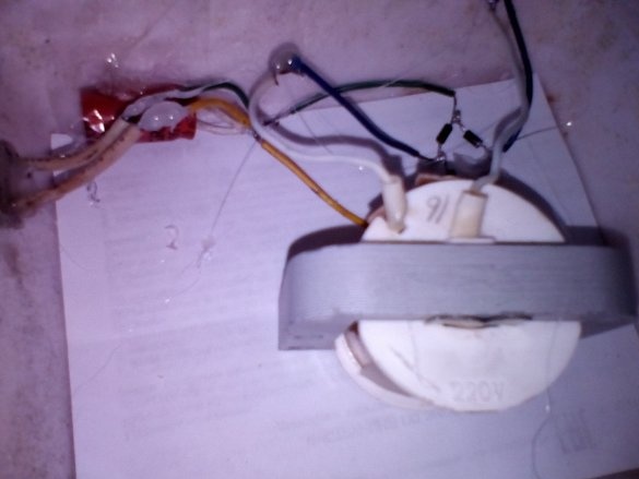
Next, you need to fix exactly in the middle of the container "our coil" on glue or double-sided tape.
We also need cardboard, the dimensions of which should be larger than the container that you use. This cardboard will play the role of the bottom.
That’s all done.
It remains to verify it.
As a study guide for children, just a little stress is most suitable and you can even start a game like who will achieve more stress in 10 seconds.


