Attentive readers noticed that in the articles of the author Instructables under the nickname WilkoL about the tuning fork generator and a clock with its use, only one frequency meter is shown, and in the article about the generator with a glass as a frequency-setting element, a second one was added to it, and he even got on the KDPV there. This story is about him.
I'm glad to work homemade the master begins with the study of the theoretical part, namely, with the choice of the method of measuring frequency. In many frequency meters, the number of periods of the input signal for a certain period of time, say, one second, is counted for this:
This method is good for high enough frequencies, but if the frequency is low, it does not allow to obtain a sufficiently large number of decimal places. For example, if the measurement cycle takes one second, then for a frequency of the order of 50 Hz, there will be zero decimal places. You want, for example, three signs - there is a way out, we extend the measurement cycle to 1000 seconds. But it’s one thing when a PC or a smartphone slows down, which everyone is at least used to, and it’s quite another thing - if a frequency meter also joins this fun company, this will completely knock the user out of himself. In general, another way is needed. But what if we measure the period of oscillations, like that?
So do too. Take a signal of the reference frequency, which is several orders of magnitude higher than the measured, and consider how many periods of the reference signal will pass in one period of the measured. So, for example, with a reference frequency of 10 MHz and measured at 50 Hz, this will be 200,000. This means that the period is 20,000.0 ms, and a modern (and, by the way, not very) microcontroller, if the programmer "teaches" it, with easily recounts the period to a frequency equal to 50,000 Hz. If the frequency increases to 50.087 Hz, then in one period of the input signal, 199650 periods of the exemplary fit in, and such a change the frequency meter will notice in real time.
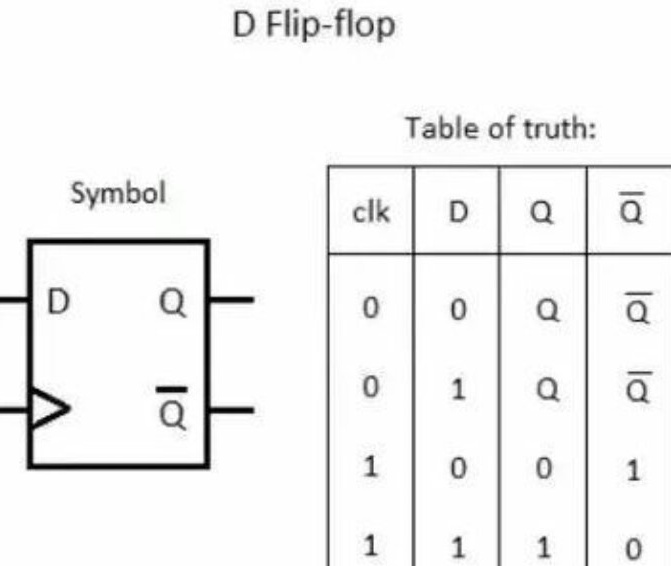
But with this method of measurement, the number of decimal places, on the contrary, decreases with increasing frequency of the input signal. For example, if it is 40 kHz, and the reference is still 10 MHz, then at 40-161 Hz we get 249 periods of the reference frequency, and at 39840 Hz - 251 periods. At least two frequency meters are in order: one for high frequencies, operating in the first way, the other for low frequencies, in the second. Although - wait! Isn’t it possible to combine both methods in one frequency meter? You can, and the master tells how. You need to take an ordinary D-trigger, then its symbol and the truth table are given:
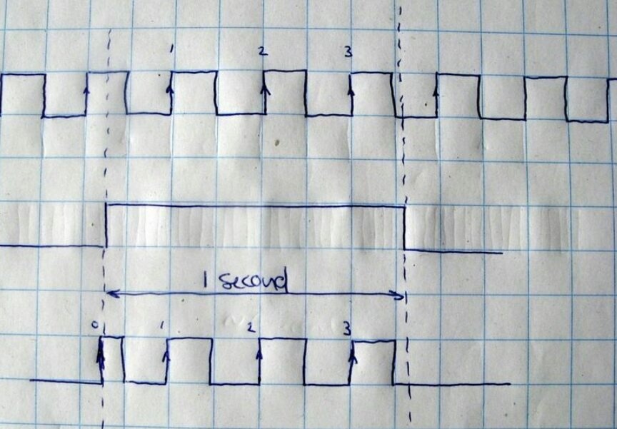
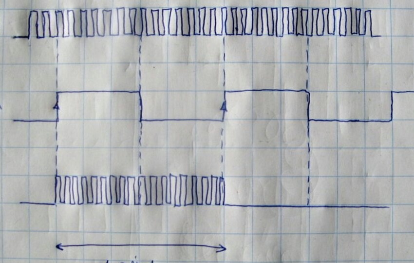
The wizard shows four signals on the chart, the fourth of which produces a trigger:
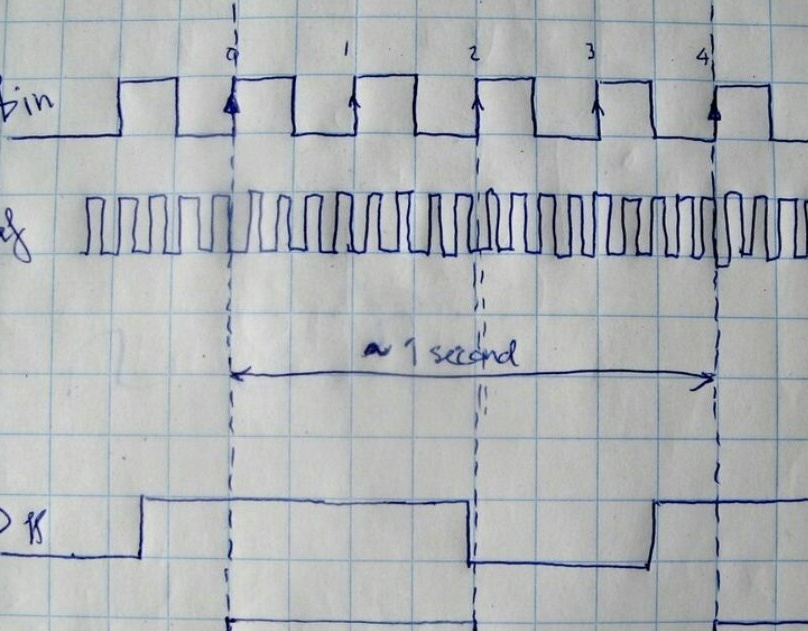
The first of these signals is the measured frequency; it is fed to the clock input of the D-trigger. The second is a reference frequency, for example, again of 10 MHz, which requires high stability. The third is a signal with a frequency of the order of 1 Hz, stability from which is not required at all, it is applied to the same trigger at input D. Well, the fourth is generated by the trigger from the first and third as follows. When the third signal switches from zero to one, the trigger does not immediately respond to this, but only when such a switch occurs with the first signal after that. Thus, the front of one of the pulses of the fourth signal coincides exactly with the front of one of the pulses of the first. Then the third signal, followed by the fourth, switches to zero, which the microcontroller does not react to in any way, then the third signal switches back to one, but the trigger does not react to it again immediately, but only after the same switching of the first signal. And again, the fronts of the first and fourth signals completely coincide. And in the full period of the fourth signal fits an integer number of periods of the first. Further - a technical matter: do not forget that we also have a second signal. The microcontroller calculates how many full periods of the first and second signals fell in the full period of the fourth.
So, we got two numbers. For example, 32 and 10185892. Multiply 32 by 10,000,000 (reference frequency) and divide by 10185892. We get 31.416 Hz. Three decimal places. And the measurement remains accurate both at low frequencies, and at high, approaching the model. And if you need to measure even higher frequencies, you can add a divider.
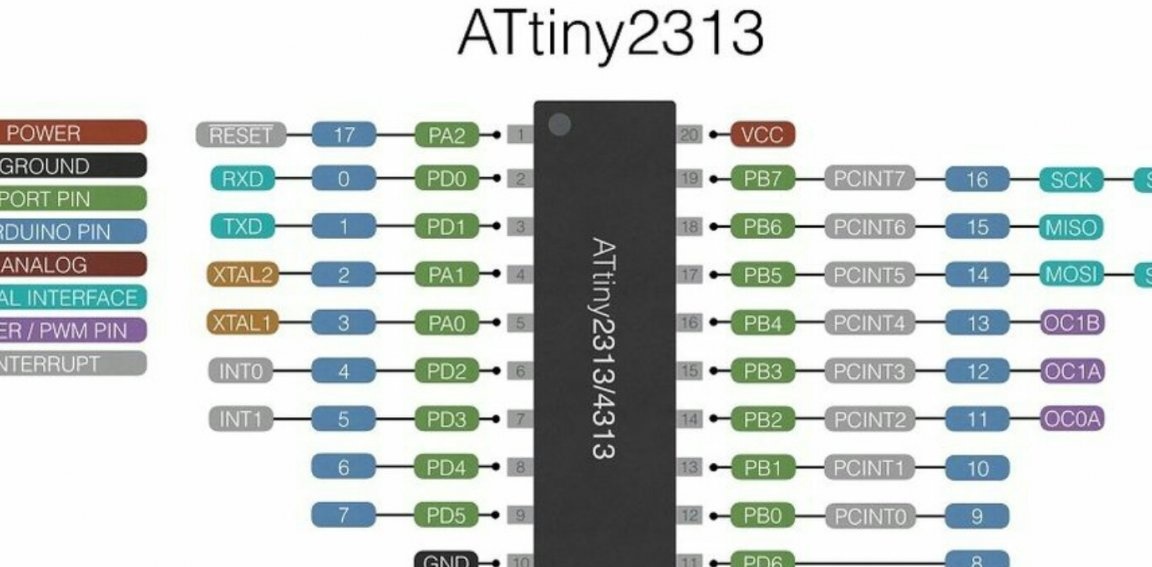
Now we need to decide on which microcontroller to run the frequency meter. The master has already tried to make them on the ATmega328, and even on the STM32F407, running at a clock frequency of 168 MHz. But this time he is imbued with minimalism and decides to check whether he can get a similar result on ATtiny2313.
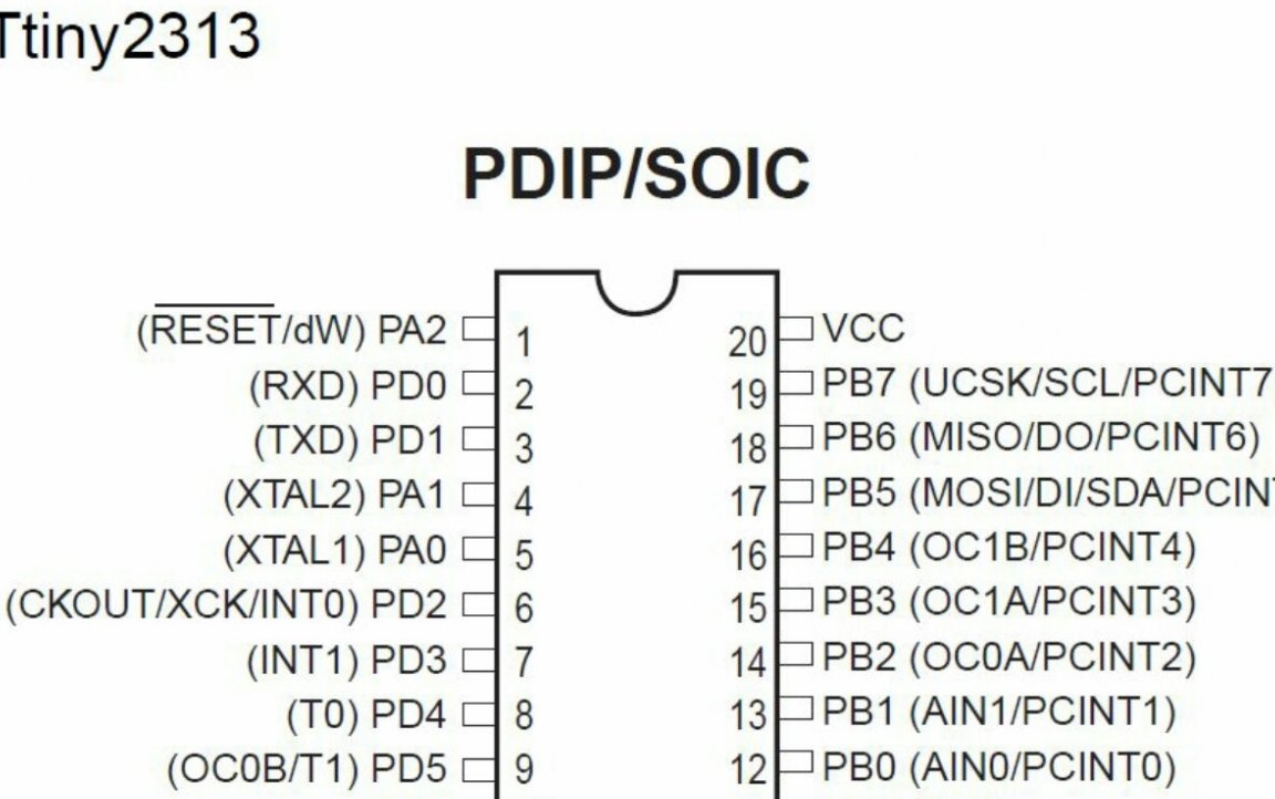
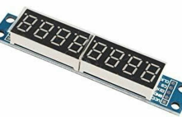
He has more than enough conclusions, especially if you use an LED display with a built-in driver chip like MAX7219:
A complete device diagram looks like this:
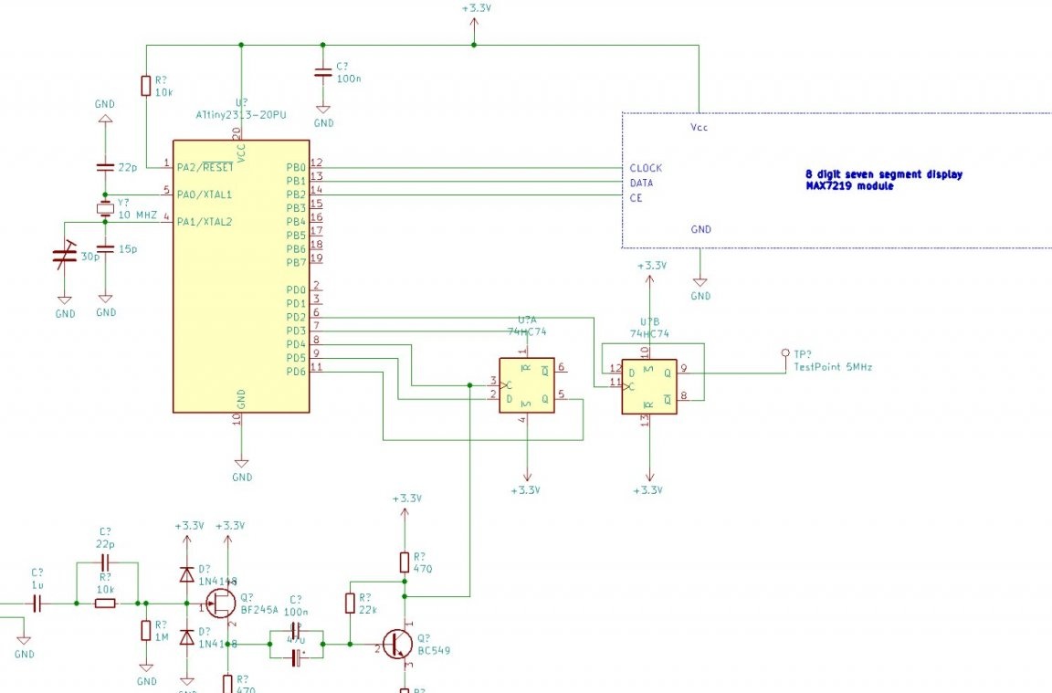
A rather complex driver for discrete components, containing RC circuits, a diode limiter, and amplifier stages, is used to obtain rectangular pulses from a signal of almost any shape. The D-trigger is located outside, the signal of the measured frequency (first) is fed to it from the driver, the signals with frequencies of 10 MHz and 1 Hz (second and third respectively) are received from the microcontroller, the output signal (fourth) goes back to the microcontroller. The second such trigger serves to generate a signal at a control point. The same PDF scheme in the ZIP archive is available. here.
Having compiled a diagram, the master collects a frequency meter on it, it turns out like this:
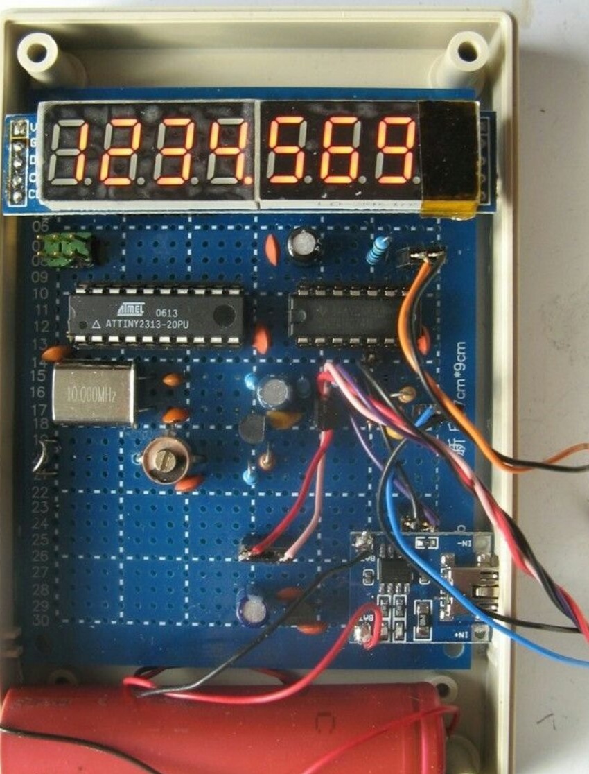
In the photo, unlike the circuit, the battery and charge controller are shown, the pulse stabilizer is also mentioned by the master, but where it is, it is not visible. All these components were added later, which made working with the frequency meter more convenient. A 18650 battery should be taken with protection, soldering wires to it is unacceptable. Either the compartment or spot welding.
Firmware (lies here also in the ZIP archive) the master writes taking into account the need to transfer the microcontroller from the clock to the RC generator to work from external quartz, as well as the possibility of assigning various functions to each of the outputs of the microcircuit:
To upload the firmware, the wizard takes an in-circuit programmer from Olimex. This is a Bulgarian company with a profile close to Adafruit.
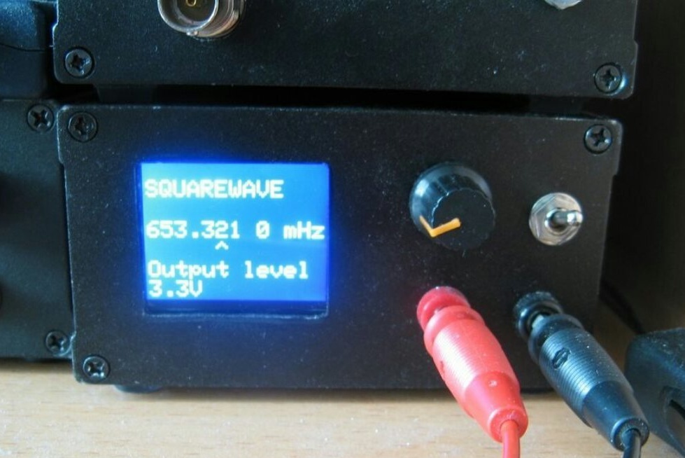
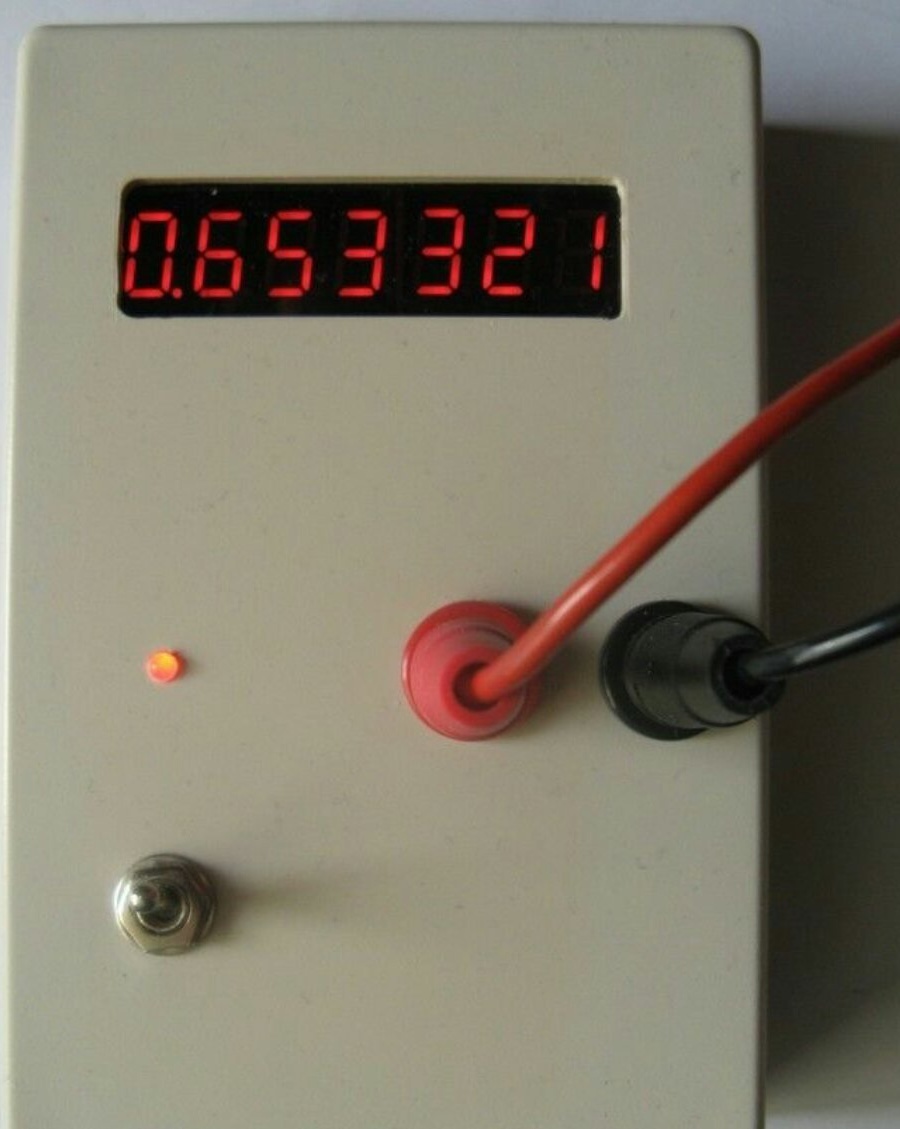
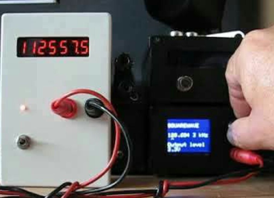
The master seals the minor discharge on the display, and then cuts a hole in the housing cover so that this discharge is closed, since its readings were inaccurate despite all the measures taken.This is affected by the features of the algorithm, and not too high temperature stability of the crystal oscillator. To set it up, the master connects an external frequency meter to the control point with frequency stabilization of the clock generator from the GPS receiver, after which it sets the exact 5 MHz by turning the tuning capacitor (the trigger divides the clock frequency by two). A correctly tuned frequency meter provides the required accuracy in the range of measured frequencies from 0.2 Hz to 2 MHz. The following two photos show how the master applied the same signal simultaneously to the reference and verified frequency meters: