
This guide will show you how to do it yourself assemble a switching power supply, which can be used for almost any task.
The author of this homemade product is Roman (YouTube channel "Open Frime TV"). About half a year ago, Roman was already assembling a power supply unit on the SG3525.
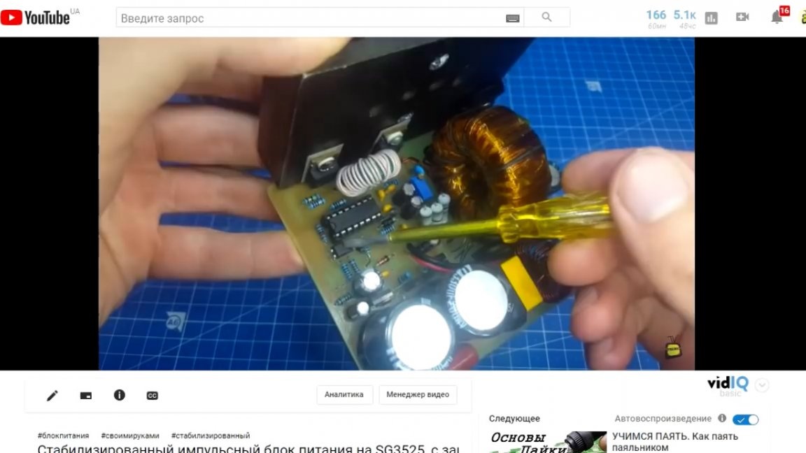
But then the author was just beginning to study pulsed technology and some mistakes were naturally made. But only he who does nothing is not mistaken. Therefore, this project was decided to start with a debriefing. So, the first and most important: in any stabilized push-pull power supply there must be a choke. Moreover, this inductor must be installed immediately after the Schottky diodes. Without this component, the circuit operates in relay mode.
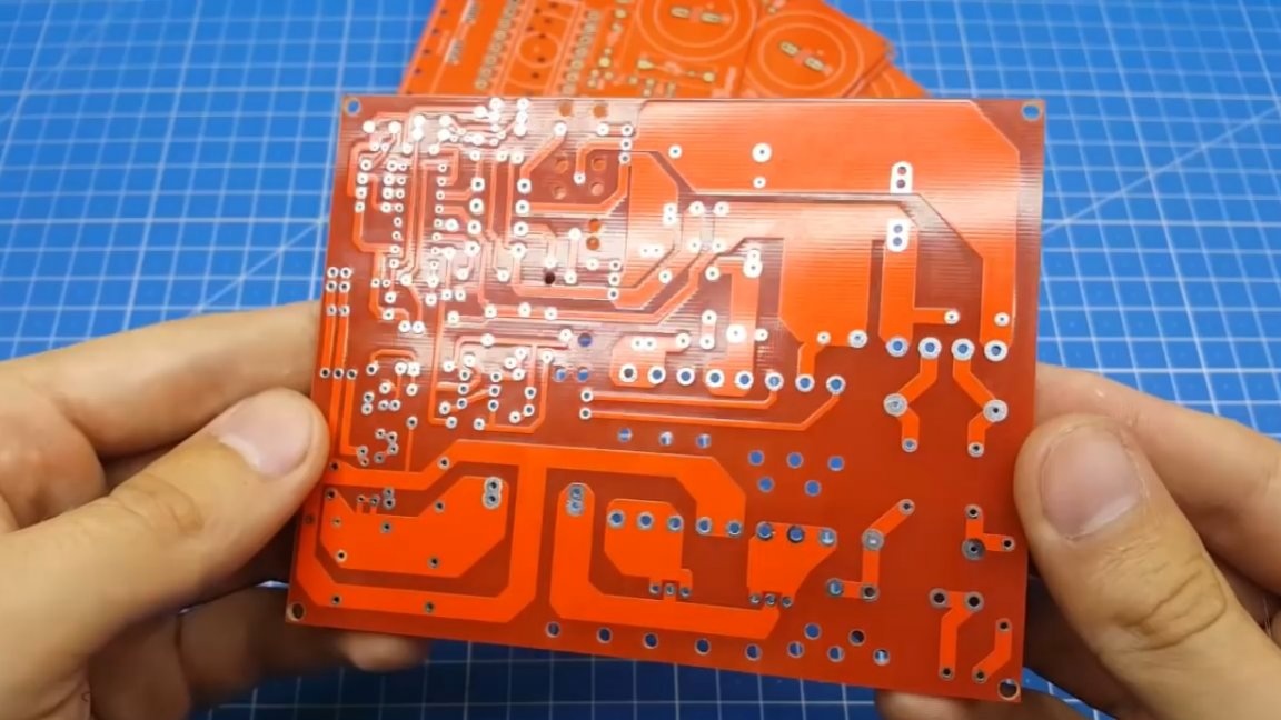
The next thing to pay attention to is PCB layout. In the first version, the tracks are thin and long.
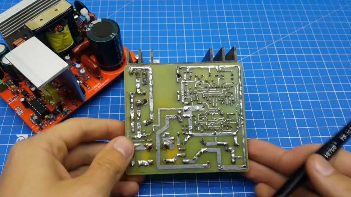
In this project, the author did everything possible to reduce the length of the tracks and, if possible, make them wider.
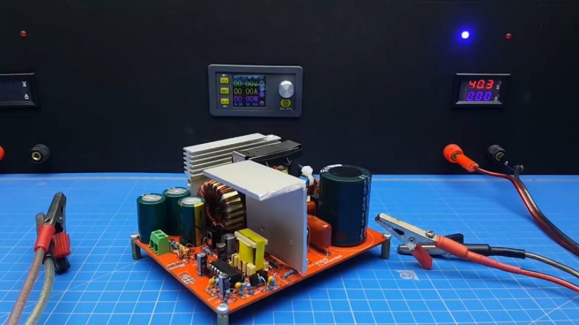
Now a few words about the characteristics of the new power supply. The maximum power that can be obtained with active cooling is about 400-500W. This switching power supply has stabilization of the output voltage, which means that the user can get any value he needs at the output.
Of course, the unit has a short circuit protection. And another feature of this power supply is that it can be made unstable. This is necessary if you use the unit for the amplifier, where PWM stabilization makes its noise in the sound.
So, with all the features sorted out, I propose to study the device diagram in more detail.
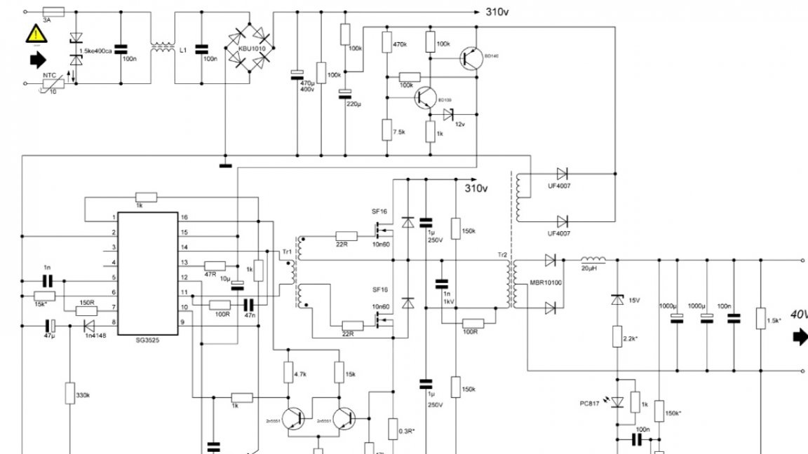
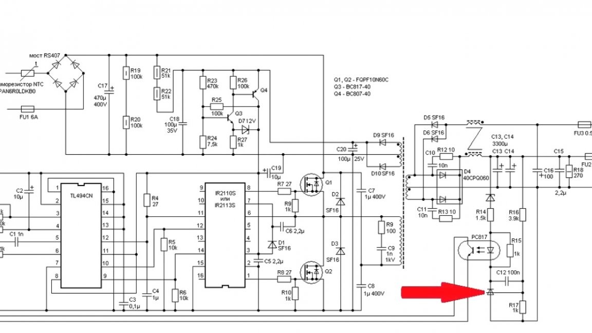
The author took the Starichka’s scheme on tl494 as a basis, where he applied tl431 as an error amplifier and started feedback directly on his third leg.
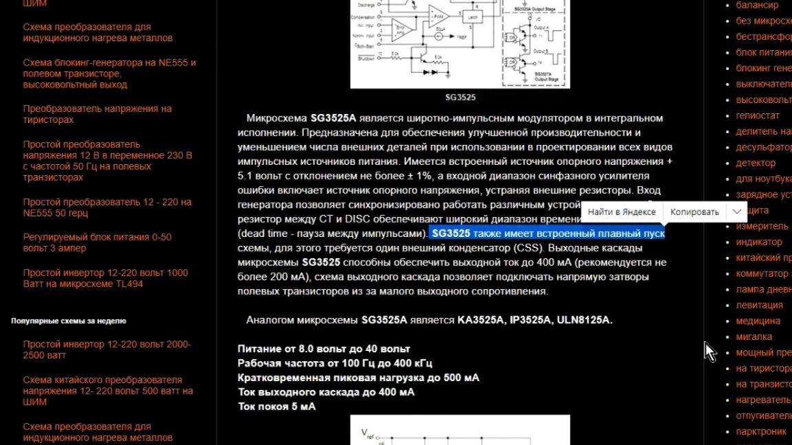
The novel did the same only on the SG3525. The choice fell on this particular chip because its arsenal has more functions, plus a rather powerful output that does not need amplification.
For protection. Not everything is perfect here. In a good way, it was necessary to install a current transformer, however, the author wanted to simplify the power supply as much as possible and had to abandon it.
Transistors can withstand short-term overcurrent, and we have current control at each cycle, so there will be no current overload at the next one, and short circuits still happen quite rarely.
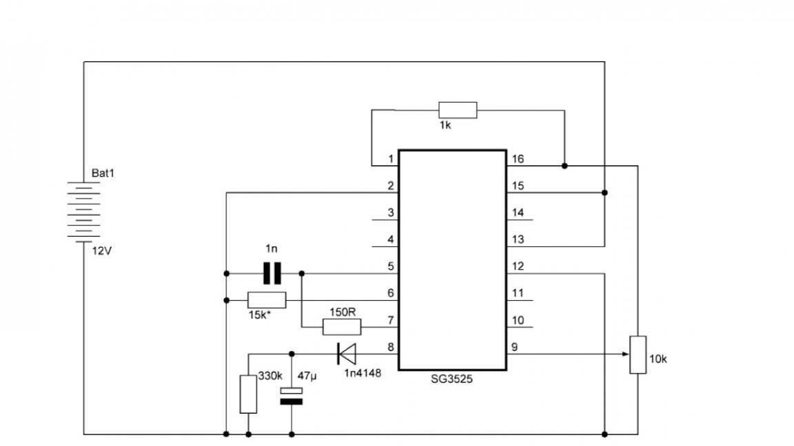
For most of you, this scheme may seem rather complicated. Therefore, let's consider it starting with the minimum strapping, and then gradually move on to the next.
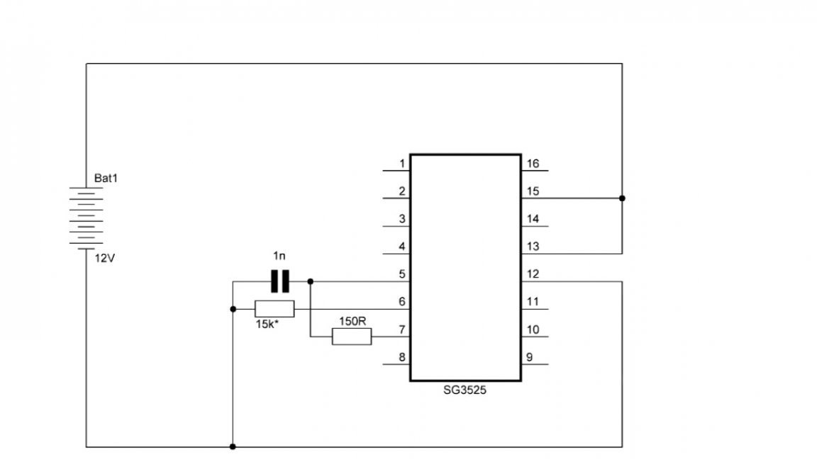
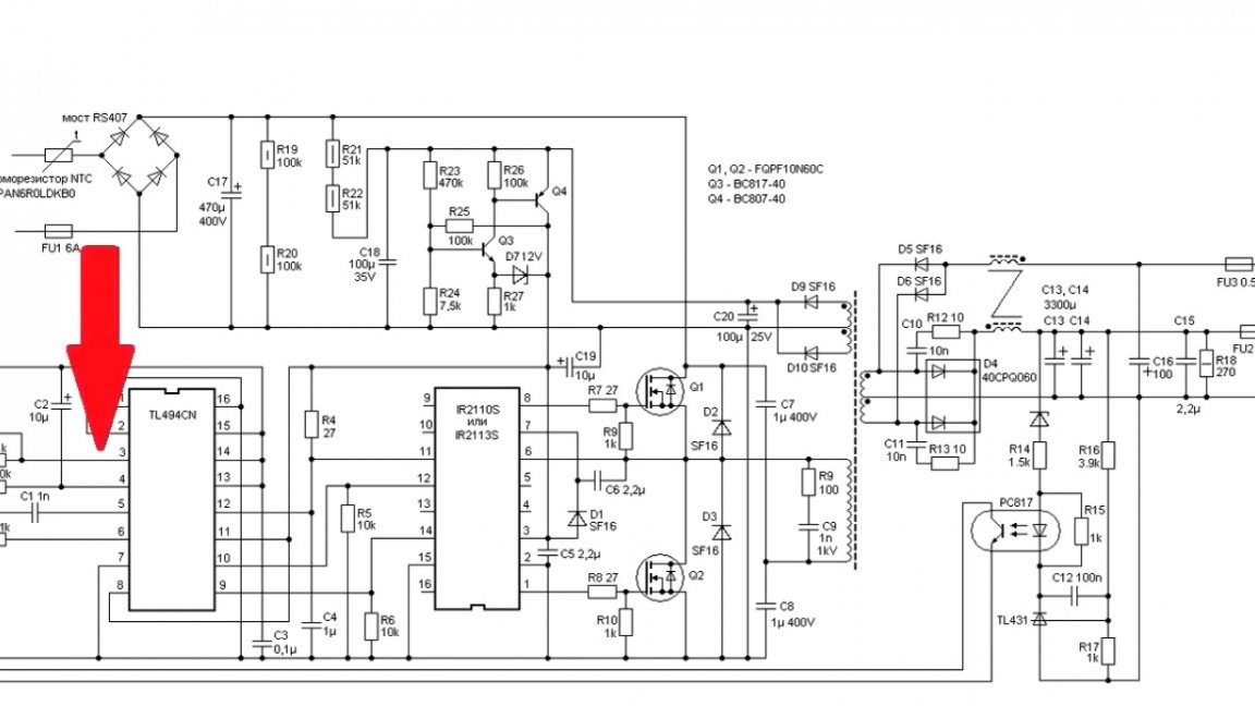
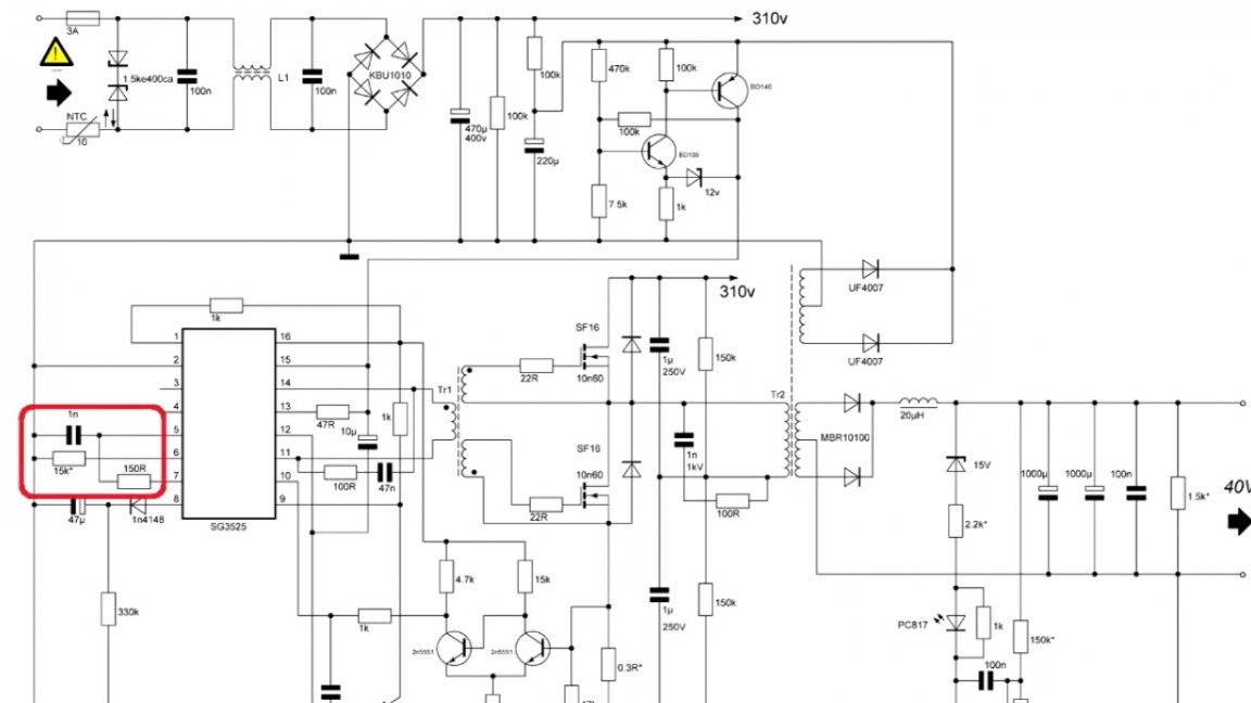
So, to start the microcircuit, it is necessary, firstly, to supply a voltage above 8V, and secondly, frequency-setting elements are needed (this is a capacitor and 2 resistors).

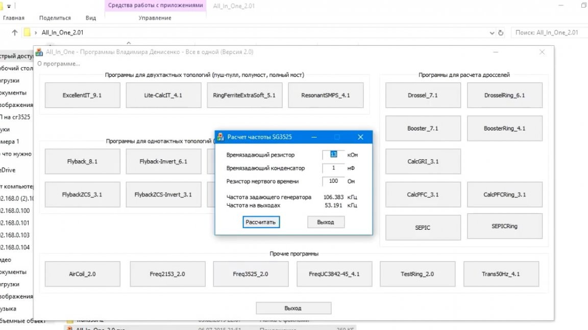
We calculate the frequency using the Old Man program.
Our circuit is ready to launch. We apply voltage to the breadboard. We place the oscilloscope probe on the 14th pin.
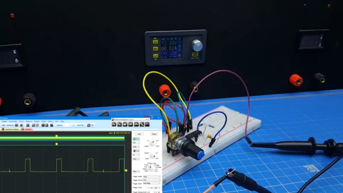
On the oscilloscope, rectangular pulses are clearly visible, which means that everything is fine - our microcircuit works.
If you start to rotate the potentiometer, you will notice that the filling width changes.
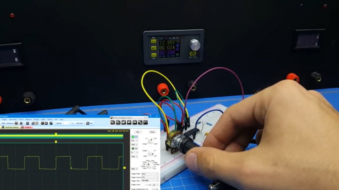
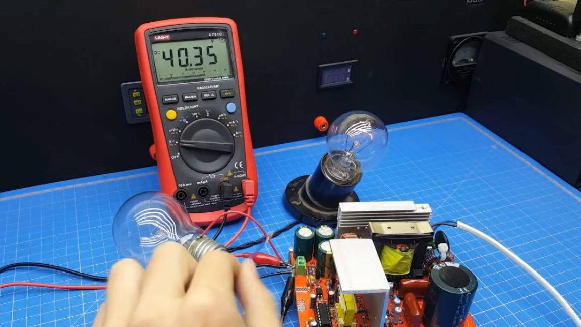
For clarity, let's connect a multimeter.
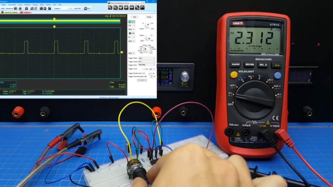

So, with a decrease in voltage, the pulses become shorter, and with an increase in voltage wider. That is how we must organize stabilization.
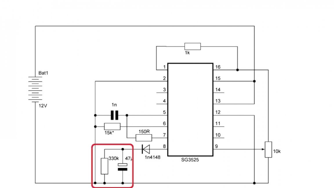
Well, we’ll get to voltage stabilization, and now we’ll get down to softstart. To do this, we connect a capacitor to the 8th output through the diode, turn on the circuit again and observe the following picture - the pulses gradually increase.
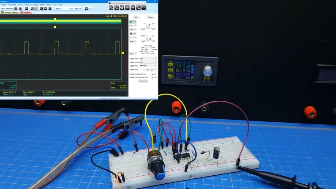

The diode in this case is necessary due to the shortcomings of certain manufacturers, since in some variations of the microcircuit the softstart capacitor interferes with the protection. Therefore, with the help of a diode, we cut it off from the circuit. The capacitor is discharged through the resistor to ground.
Now a few words about the elements that need to be calculated. Firstly, this is the frequency setting part.
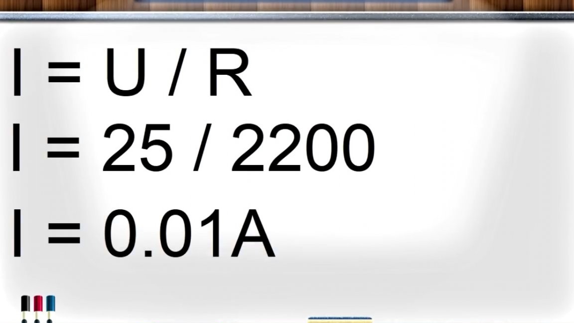
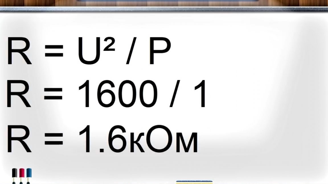
Next is the shunt of the lower transistor circuit. The calculation must be done in such a way that at rated load it drops 0.5V.
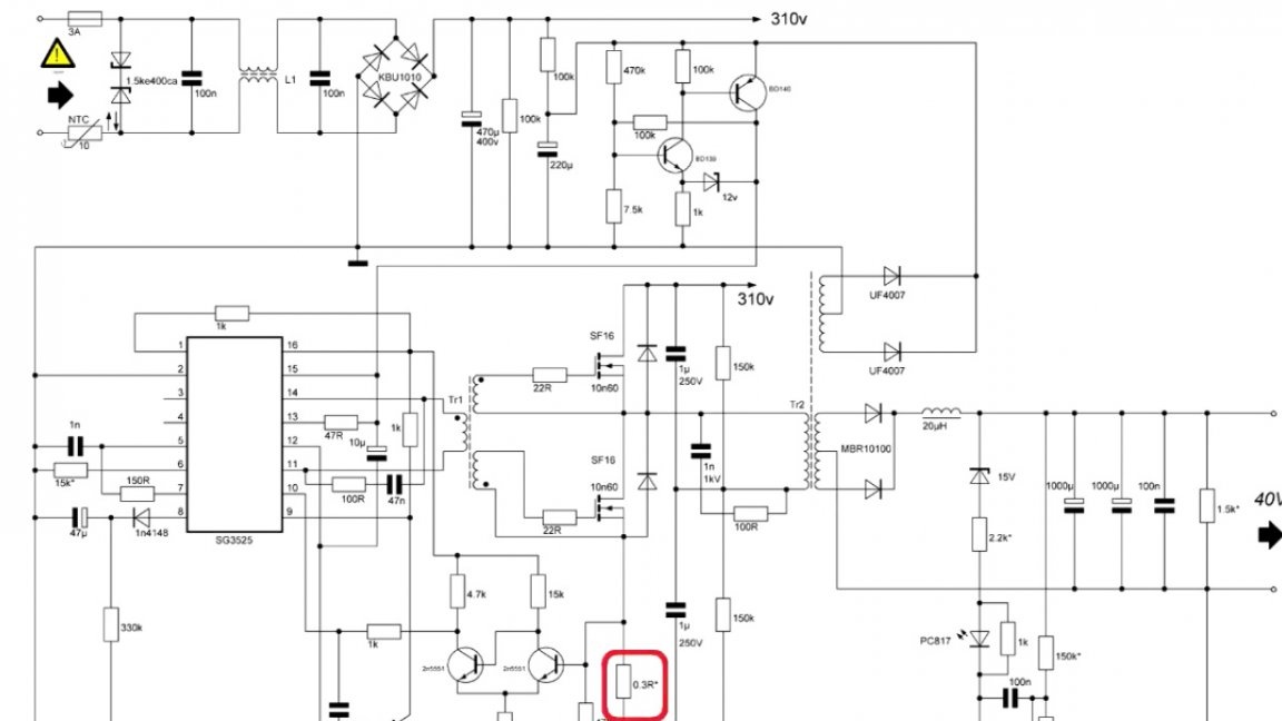
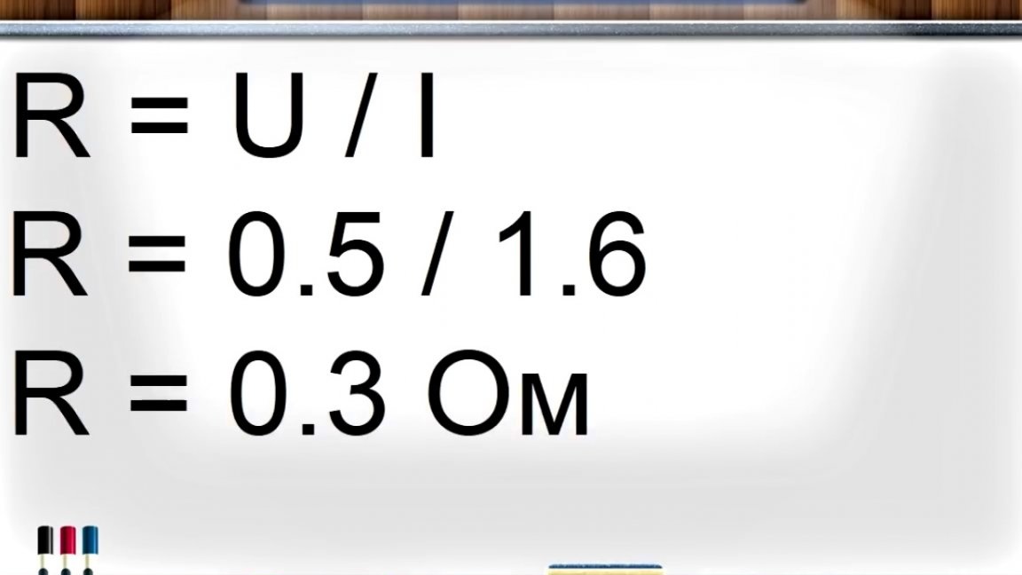
For calculation we use Ohm's law.

The current value will be obtained when calculating the transformer, it will be here:
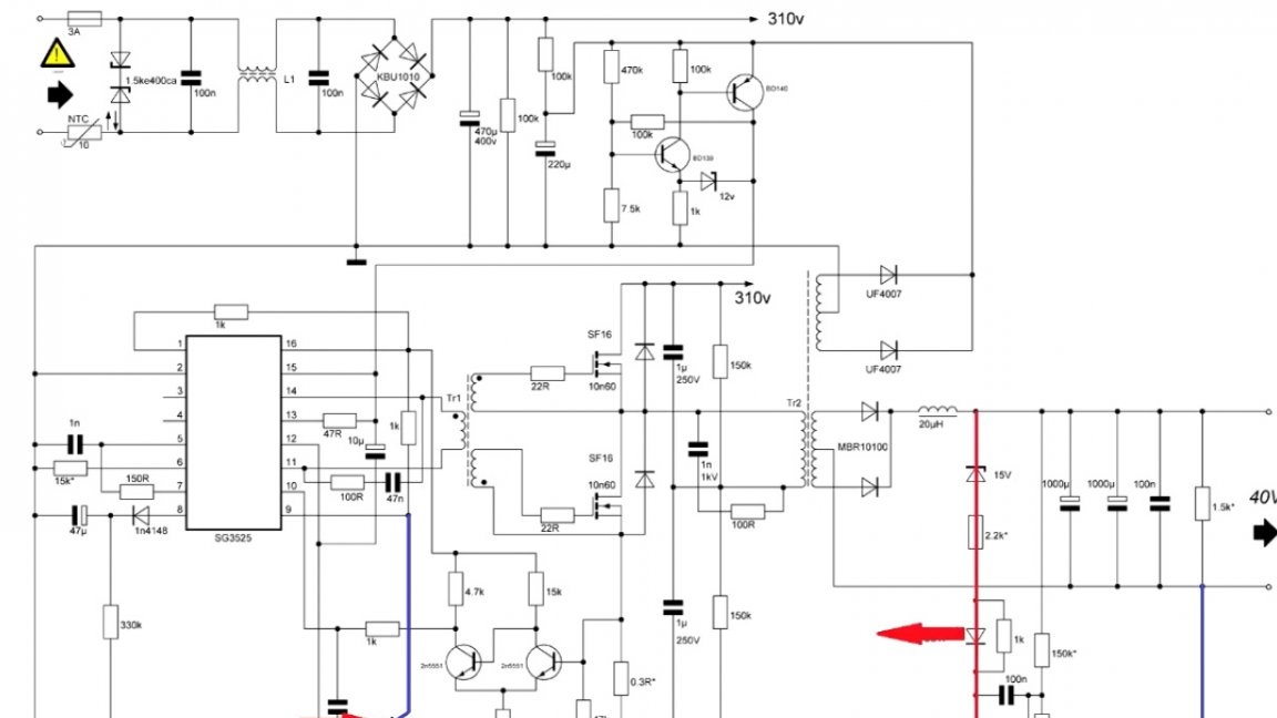
It is also necessary to calculate feedback. In this case, it is multifunctional. If the output voltage exceeds 35V, it is necessary to install a zener diode.
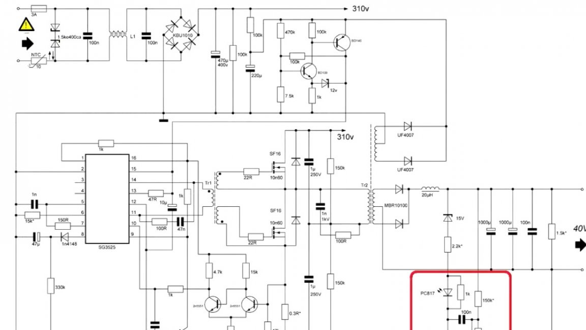
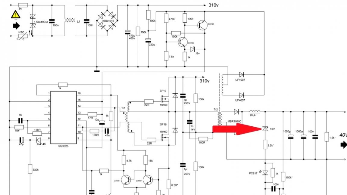
And if the voltage is less than 35V, then put a jumper.
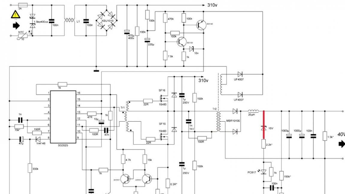
In this case, the author used a 15V zener diode.
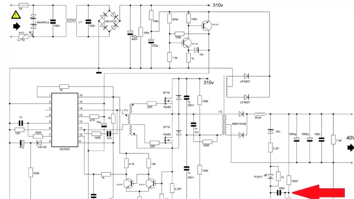
In the same circuit, it is necessary to calculate the resistor limiting the current of the optocoupler to 10 mA, the formula in front of you:
It is also necessary to calculate the voltage divider for tl431. At rated voltage, the division point should be exactly 2.5V.
The principle of stabilization is as follows. At the initial time, when the voltage divider is less than 2.5V, tl431 is locked, therefore, the optocoupler LED is off and the output transistor is closed, the output voltage rises.
As soon as 2.5V becomes on the divider, the internal zener diode breaks through and the current begins to flow through the optocoupler and illuminates the diode, which in turn opens the transistor.
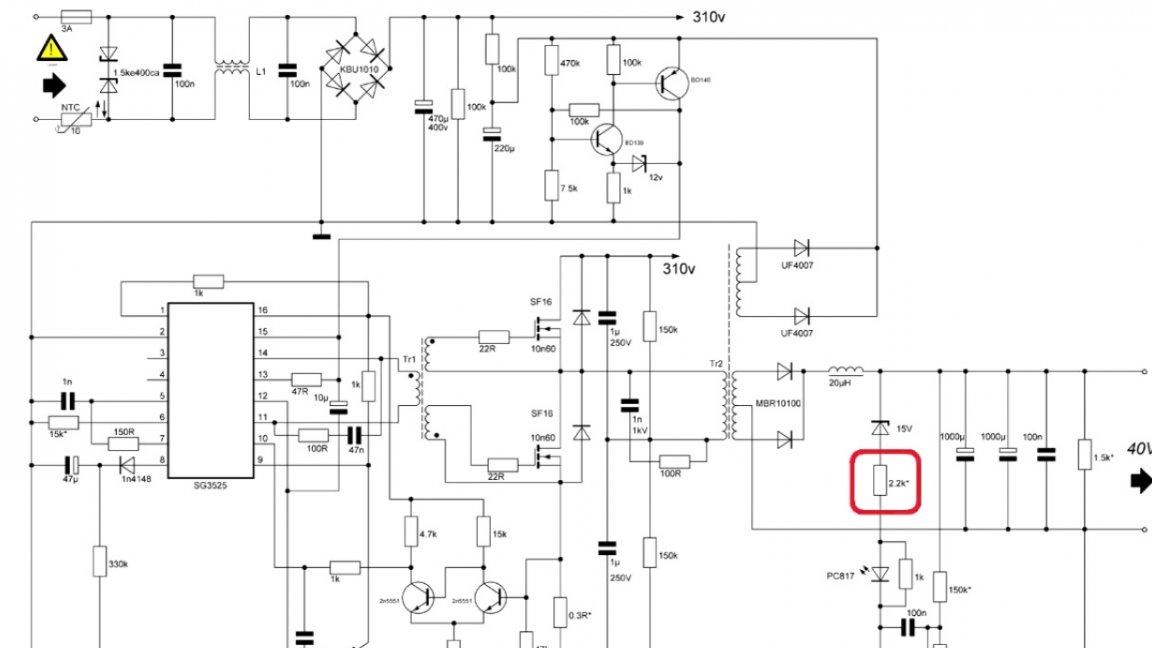
Further, the tension on the 9th leg begins to decrease. And if the voltage decreases, then the PWM filling decreases. This is how stabilization works in this way. Also, this load resistor can be attributed to stabilization:
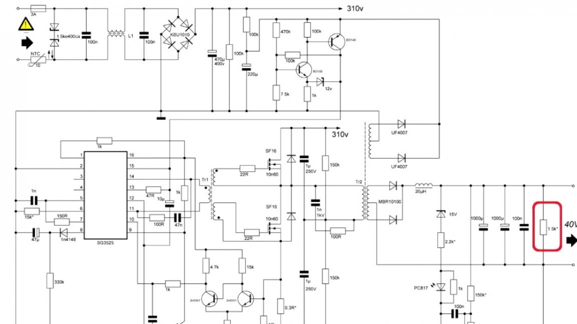
This component creates a certain load for the stable operation of the power supply in idle mode.
In more detail, all the necessary calculations, as well as the steps for assembling a switching power supply are presented in the original Author’s video:
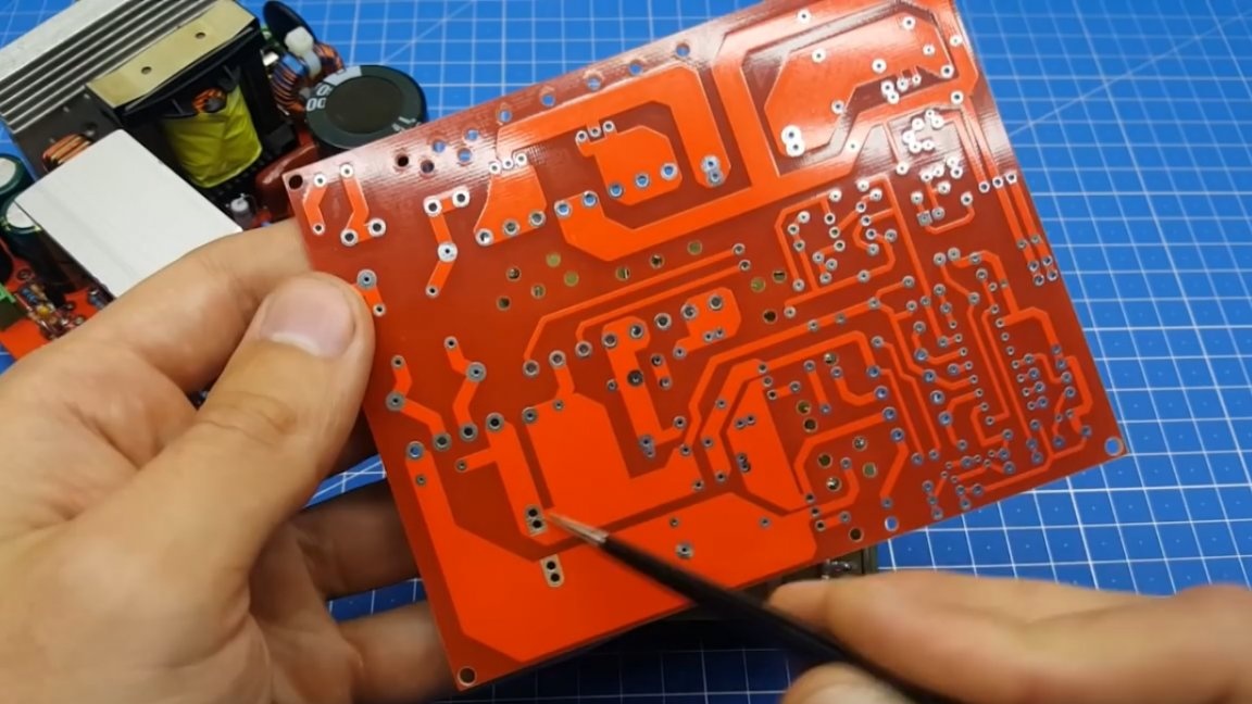
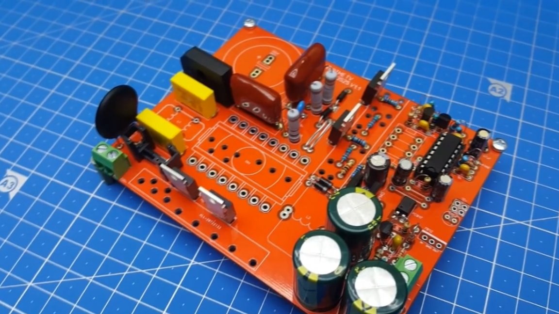
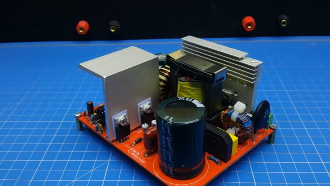
PCB layout has been given special attention. The author spent a lot of time on this, but as a result everything turned out more or less correctly.
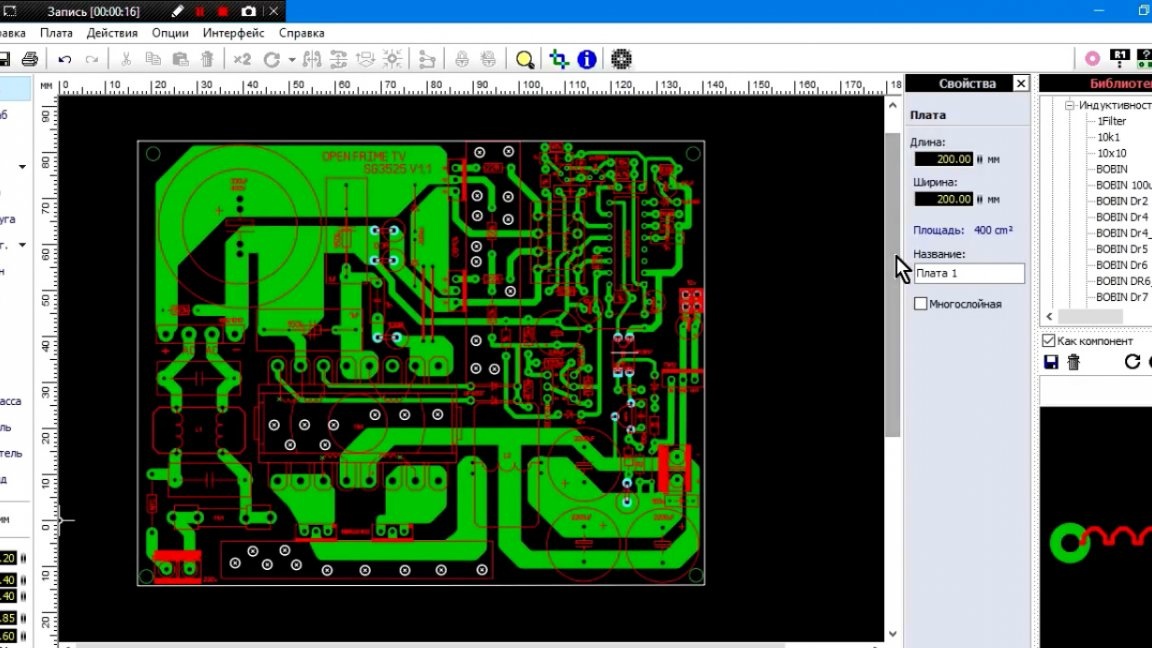
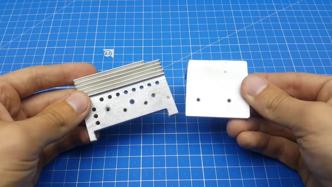
Under all warming parts there are special openings for cooling. The place under the radiator is such that the radiator from the computer power supply is excellent here.
The board itself is one-sided, but when displaying the gerbera file, it was decided to add the top layer, purely for beauty.
We begin to solder the components of the board, it will not take much time.
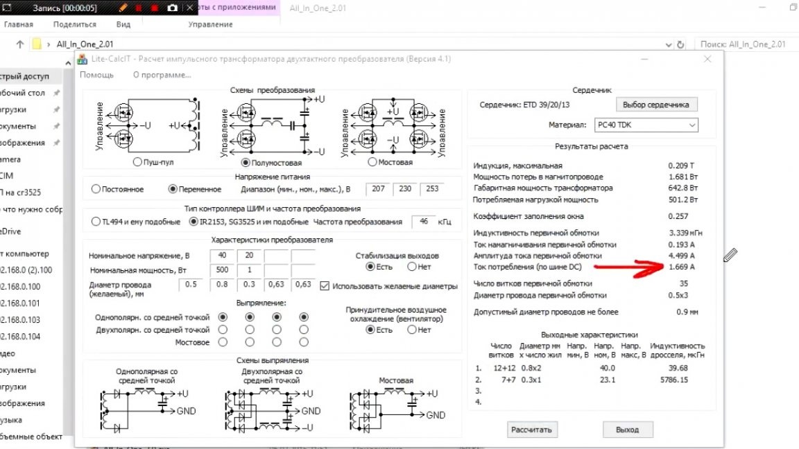
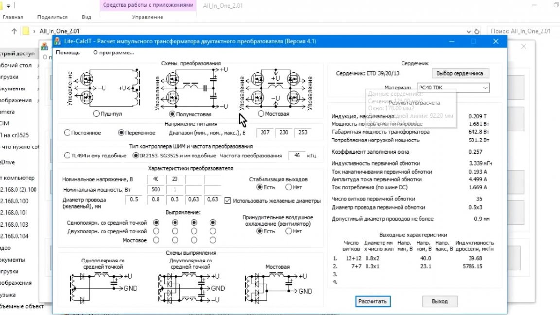
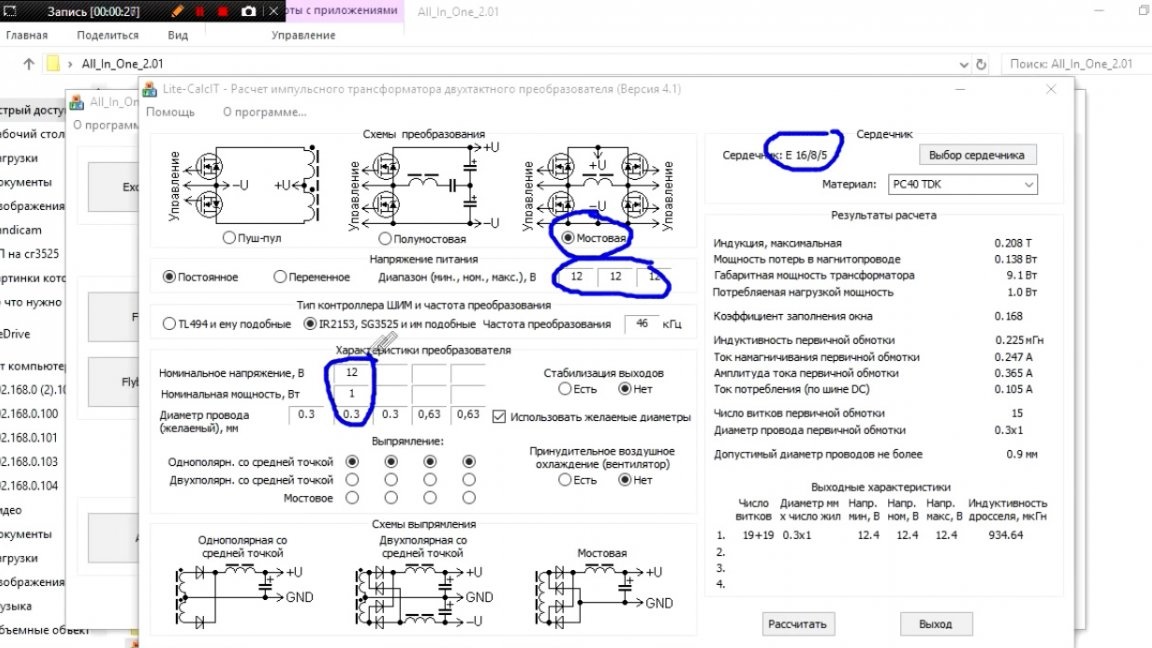
But then we will have the most difficult - winding a power transformer. But first, it must be calculated. All calculations are performed in the program of the same old man. We enter all the necessary data, and also indicate what we want to get at the output, namely the voltage and power, this is nothing complicated.
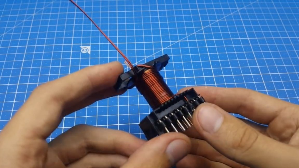
We proceed directly to the winding. Divide the primary into 2 parts.
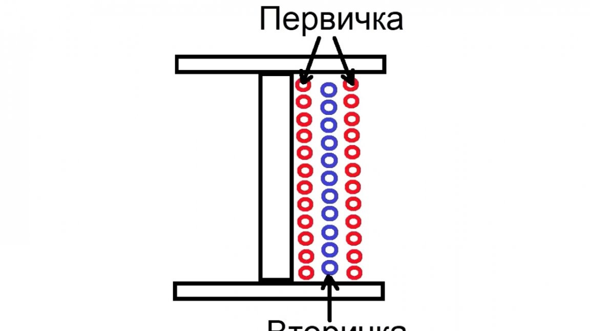
We wind all the windings in one direction, the beginning and end are shown on the printed circuit board, there should be no difficulty in winding.
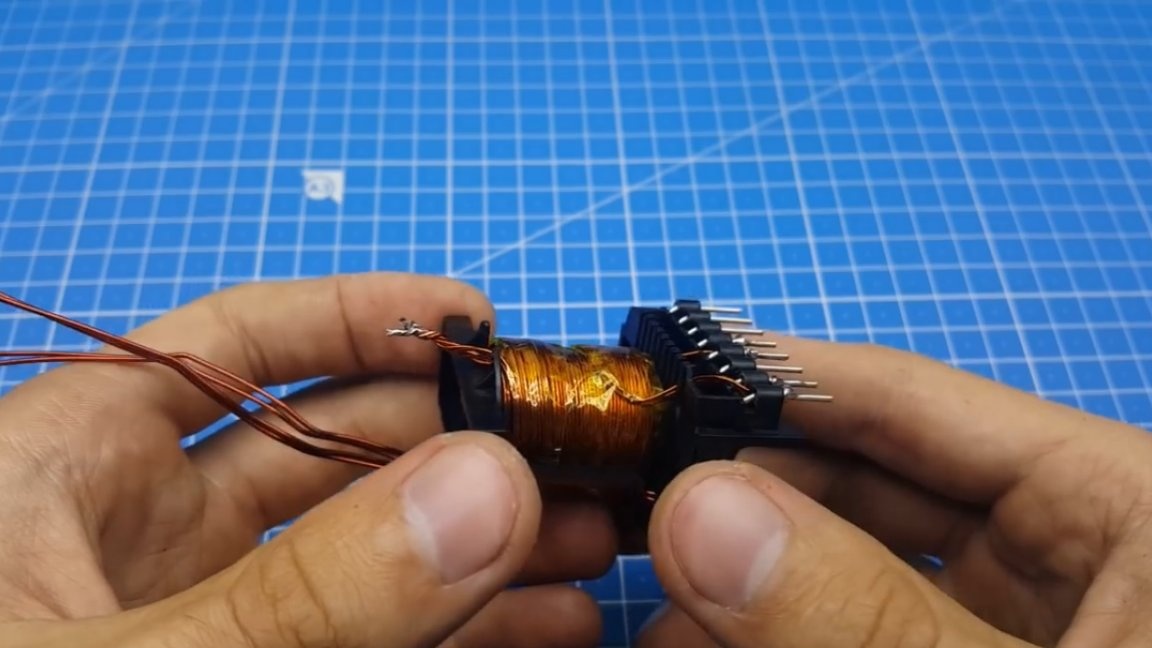
Next, we proceed to the calculation and winding of the next transformer. The calculation is performed in the same program, we only change some parameters, in particular the type of converter, in our case there will be a bridge, since the full voltage is applied to the transformer.
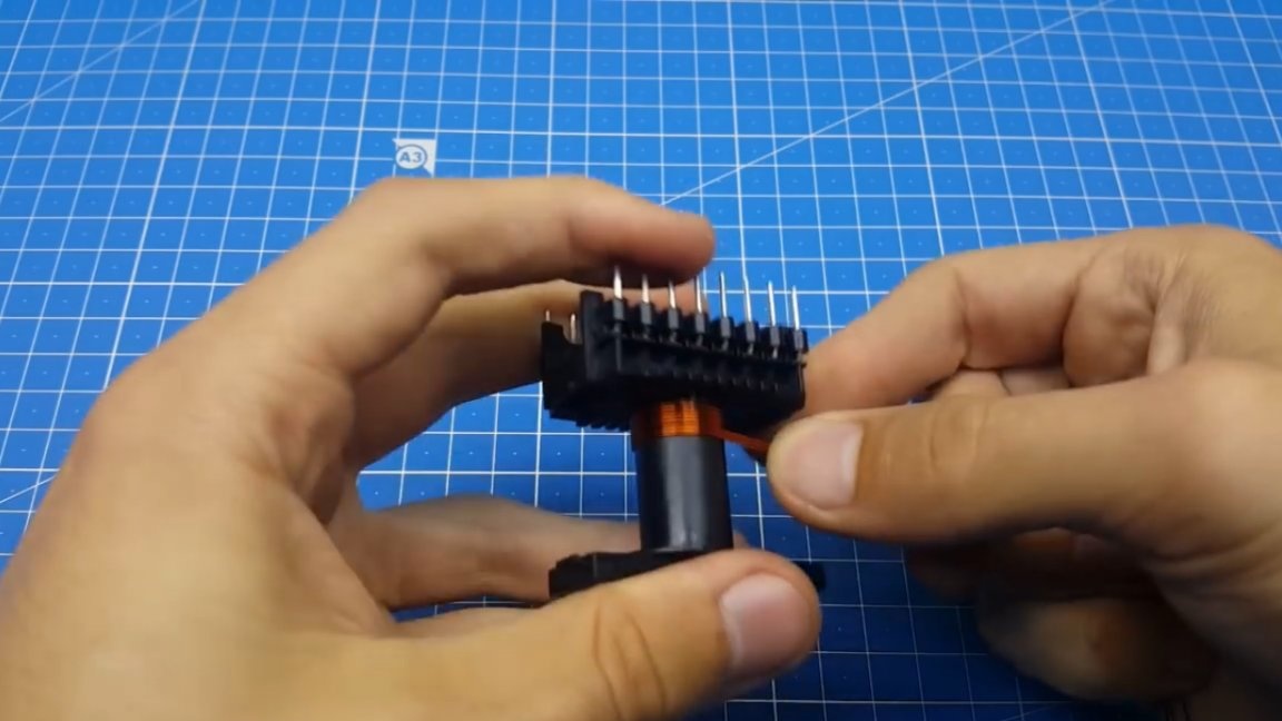
When winding this transformer, we try to fit the windings in one layer.
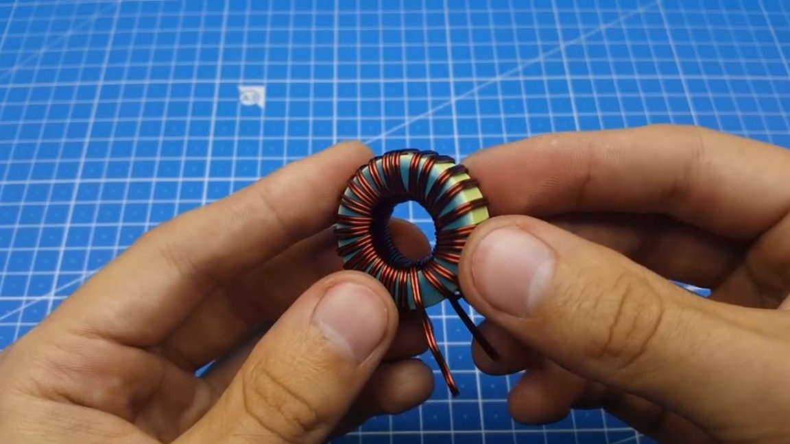
Next, we wind the output choke. It must also be calculated and wound on an iron powder ring.
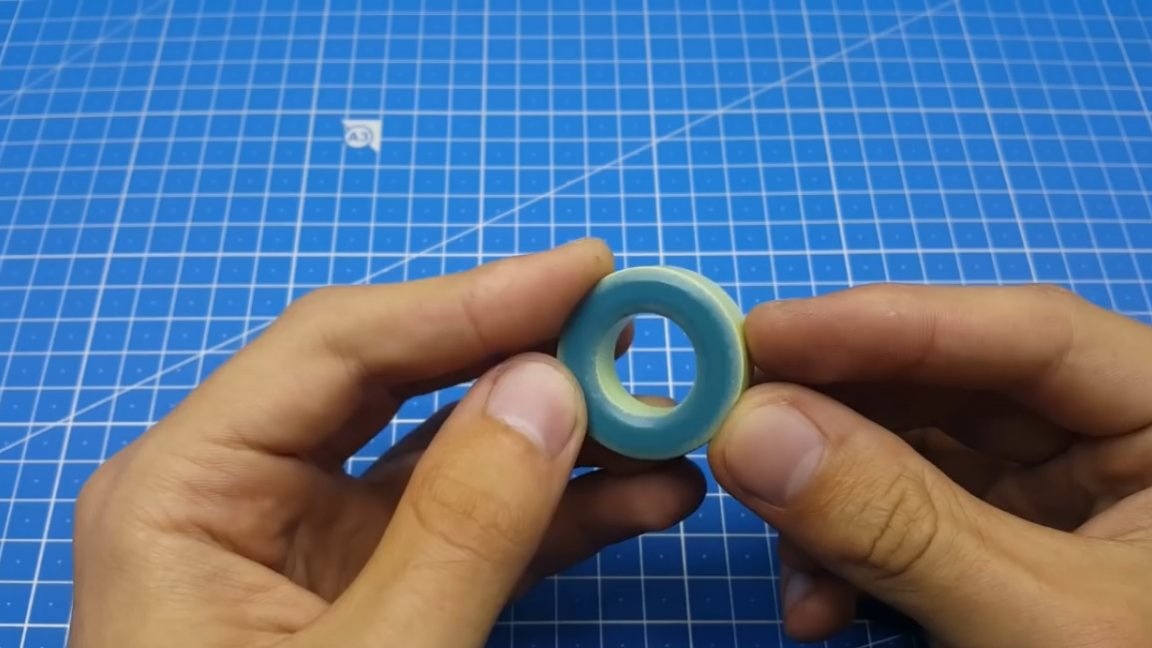
There is nothing complicated in winding the inductor, the main thing is to distribute the winding evenly throughout the ring.
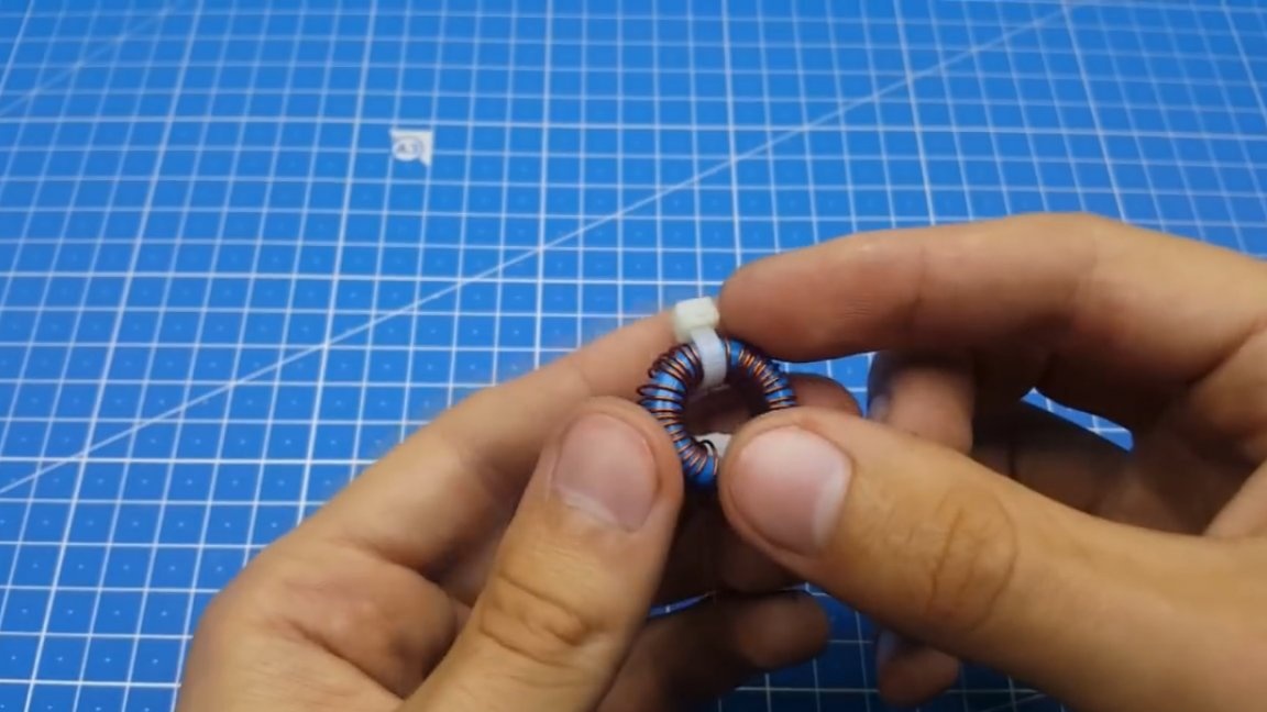
And it remains to make an input choke.
On this assembly is fully completed, you can proceed to the tests.
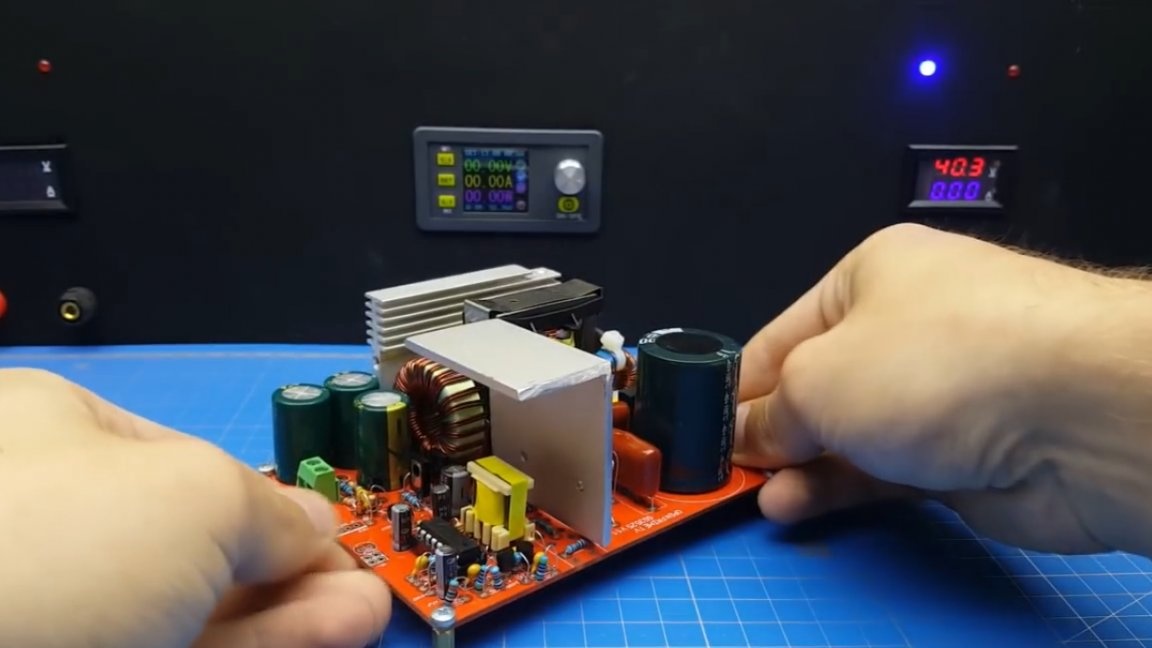
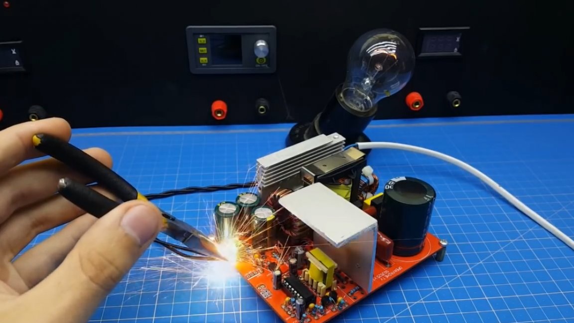
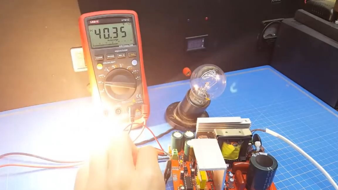
Stabilization of the output voltage fulfills as expected. Protection against short circuit is also in perfect order, the unit continues to operate normally.
That's all. Thank you for attention. See you soon!