
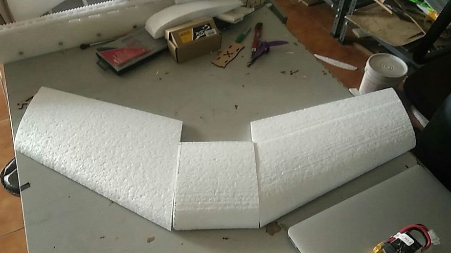
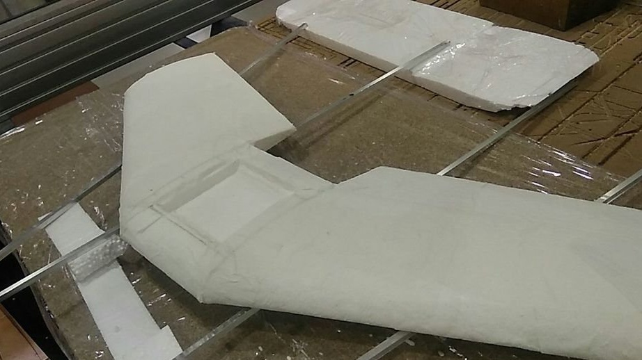
A foam cutter is a great tool for making parts for aircraft. This machine allows you to accurately cut any shape of the aerodynamic profile according to CAD.
The machine has a nichrome wire stretched between two guides. Current is passed through the wire, the wire is heated, and the guides move, cutting out complex contours, such as conical wings. Each axis is driven by a stepper motor through the spindle, GT2 belt and pulley. The cutting force should be minimal and the structure must be stiff enough to withstand the tension of the wire stretched between the supports.
This is a real 4-axis machine that can cut different shapes on both sides at the same time, so the problem arises of how to control four independent axes at the same time. Many tutorials focus on 3-axis machines, such as 3D printers, but there seems to be insufficient documentation on creating a 4-axis machine using readily available parts and open source software. The master found several people who did similar projects using Arduino and Grbl, and decided to make his own machine.
Tools and materials:
- Plywood (12mm);
-Metal rods;
- Lead screw (M8 x 600 mm);
-Motor coupling M8-M5 (M8 for the lead screw and M5 for the motor shaft);
-Arduino Mega 2560;
-RAMPS 1.4;
-Step engines (one for each axis);
-A4988 Stepper driver (one for each stepper motor);
- 12V power supply for Arduino + Ramps;
-Variable power supply (Lipo chargers with Hot-wire mode);
-Nichrome wire;
Step One: Software
The hard part of creating a 4-axis CNC is finding software to generate the G code and control the machine. A software search led to the creator of https://www.marginallyclever.com/2013/09/how-to-build-a-4-axis-cnc-gcode-interpreter-for-arduino/, developed by Marginally clever, which uses Arduino Mega 2560 and CNC Ramps 1.4 screen.
Some information has been used by the following authors: Rckeith and rcgroups.com
Grbl Hotwire Controller.zip
GRBL8c2mega2560RAMPS.zip
FoamXL 7.0.zip
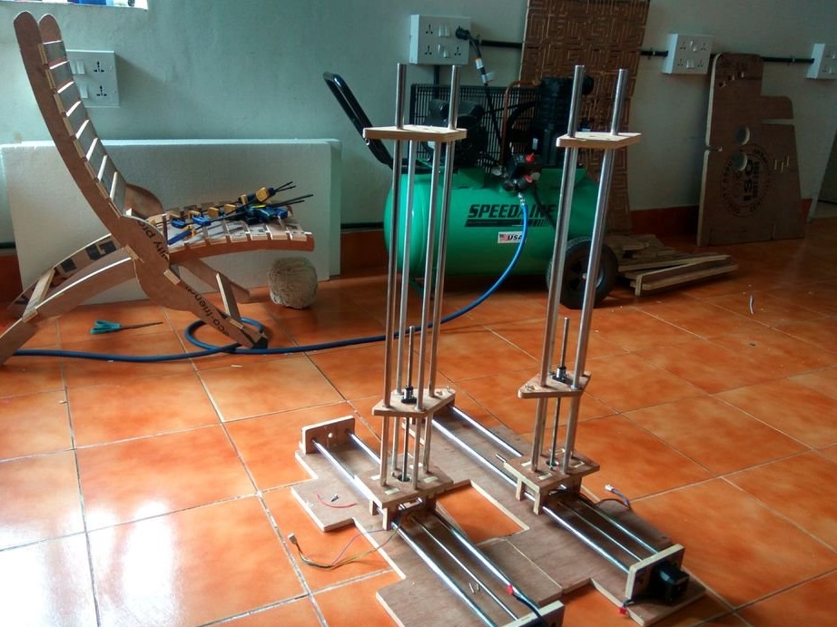
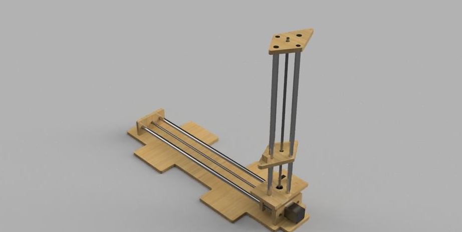
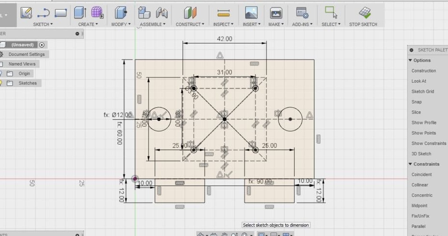
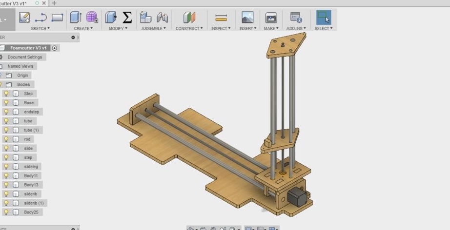
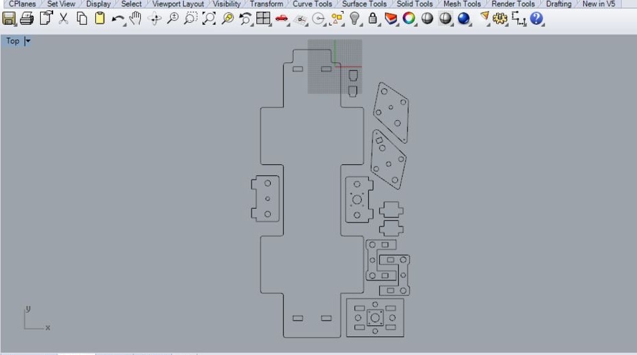
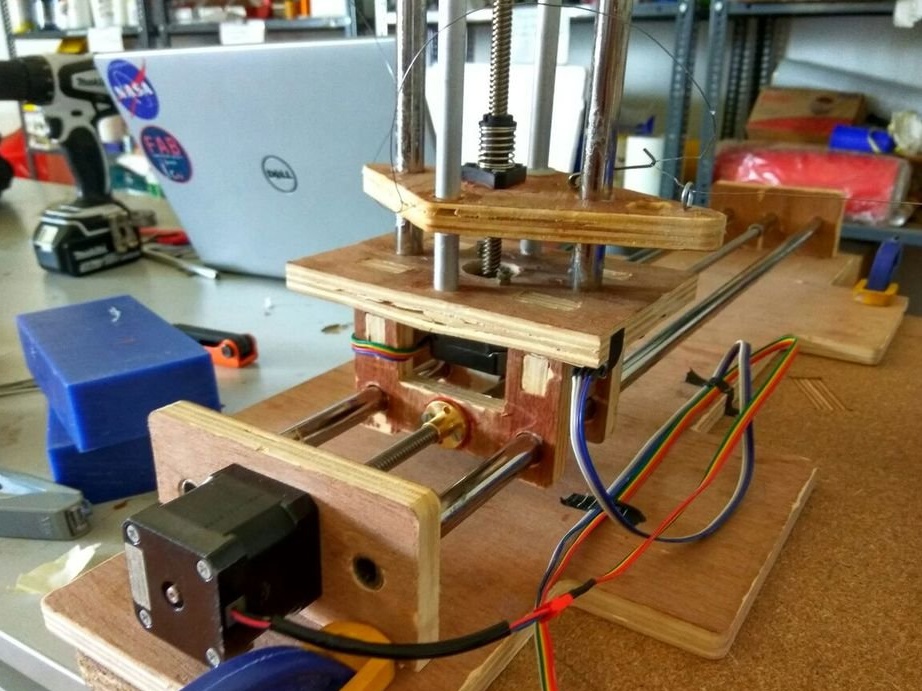
Step Two: Machine Assembly
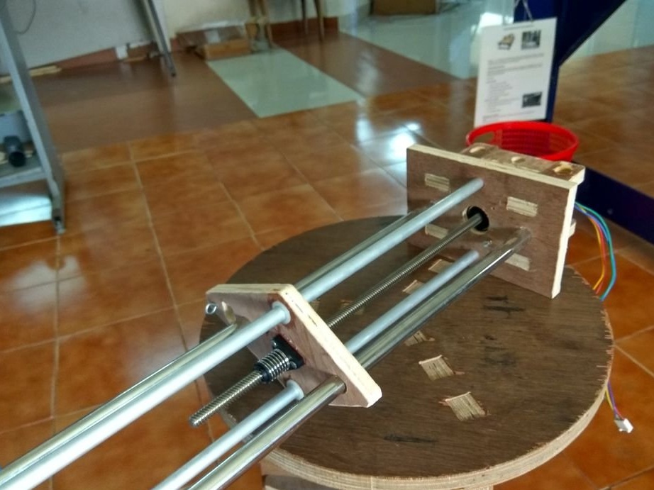
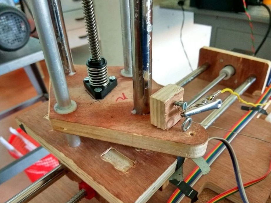
The design is made of 12mm plywood, the linear assembly is made of steel pipes with a diameter of 1/2 inch with plywood sliding blocks. The design of the sliding blocks can be improved by installing a linear bearing or sleeve.Since the master uses a lead screw, he has enough torque to overcome friction without a bearing. Two steel pipes support and hold the guide block on the same axis.
Vertical pillars are placed on top of the horizontal guide block. It has four pipes.
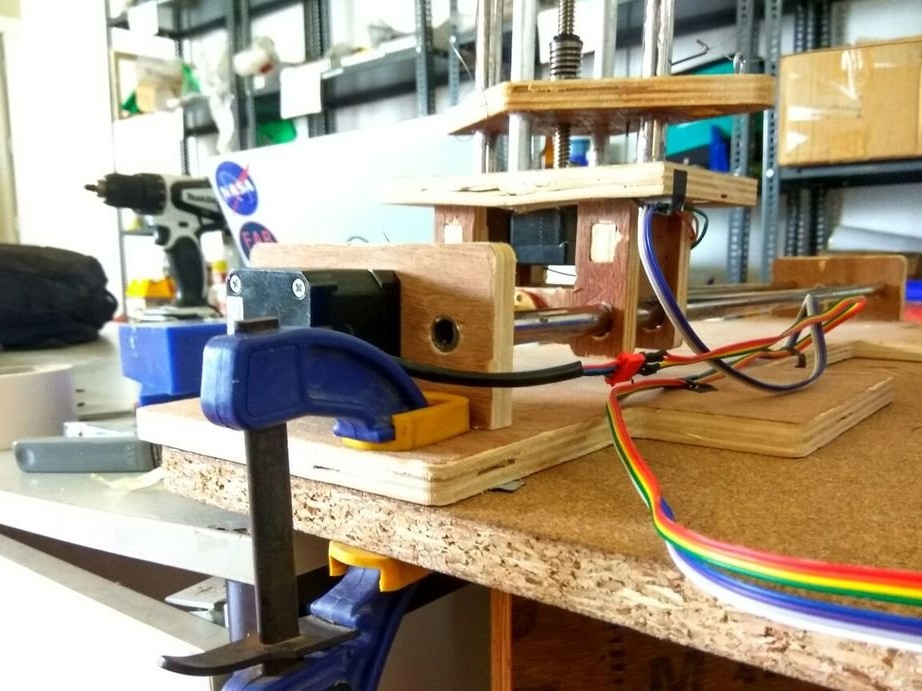
The drive screw is attached to the stepper motor using a flexible coupling. This helps with any slight misalignment of the shaft and screw. The upright has a stepper motor with a built-in lead screw, which can be purchased or replaced with a conventional stepper motor and clutch.
The two machine stands are identical. The base provides a place for mounting the machine to the desktop.
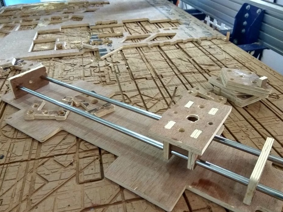

Note. When using plain bearings, depending on the material, a phenomenon called “sticking and slipping” can occur. This may cause the movement to become uneven and cause vibrations. It can also lead to blockage, resulting in excessive loads and skipped steps when using a stepper motor.
Foamcutter_base.dxf
Step Three: Connect Electronics
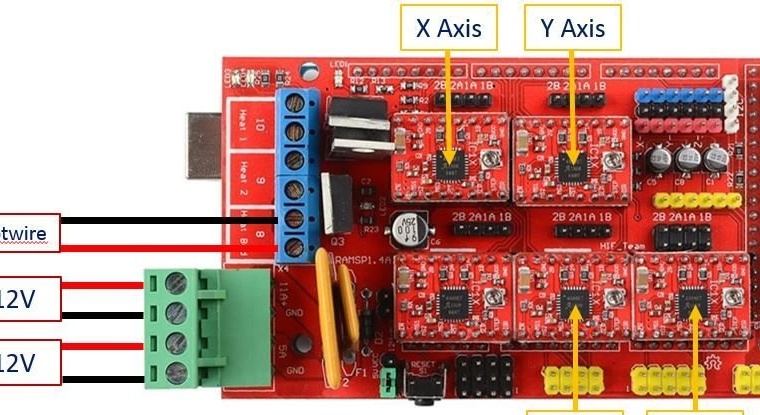
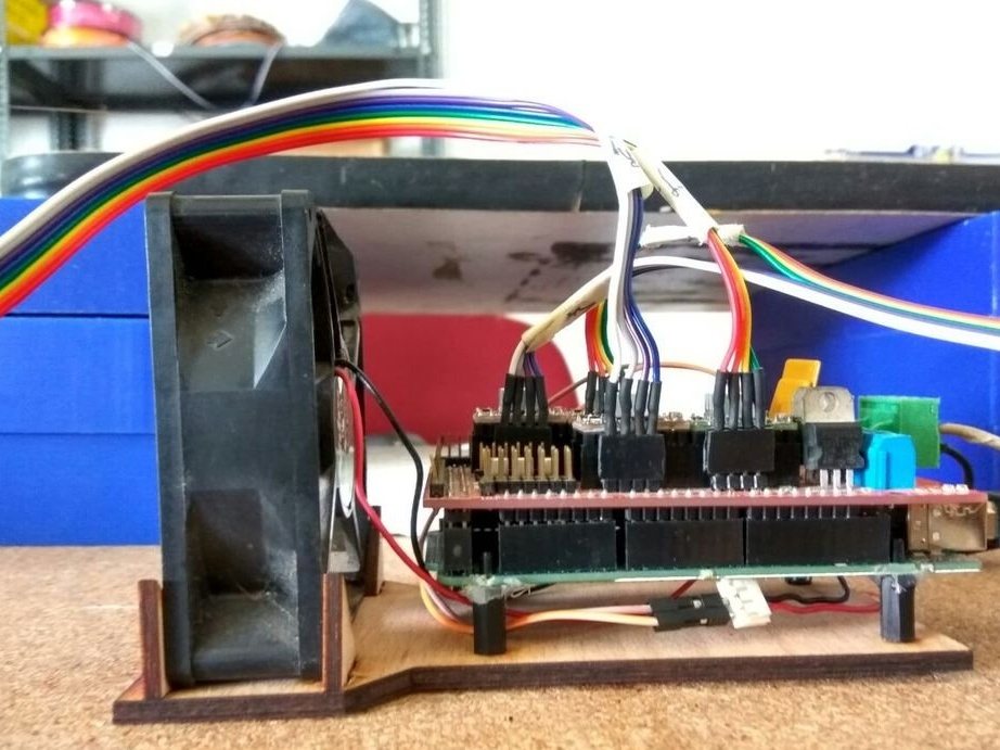
The next step is to connect the electronics, move the motors and set up the machine. There are 4 stepper motors that need to be connected to the Ramps platform. Wires must be laid all the way to ensure sufficient axle movement.
All wiring is connected to the Ramps board, which is a CNC screen for the Arduino Mega2560. Ramp can support up to 5 stepper motor drivers such as the A4988. The master uses Nema 17 engines.
Before installing on a Ramps board, make sure the A4988 chip is oriented correctly. Each stepper motor can pull up to 2 A, the stepper motor drivers are equipped with radiators for heat dissipation. The board also has a MOSFET 11A to control the temperature of the wire connected to pin D8. All components of the board are heated, make sure that proper cooling is ensured.
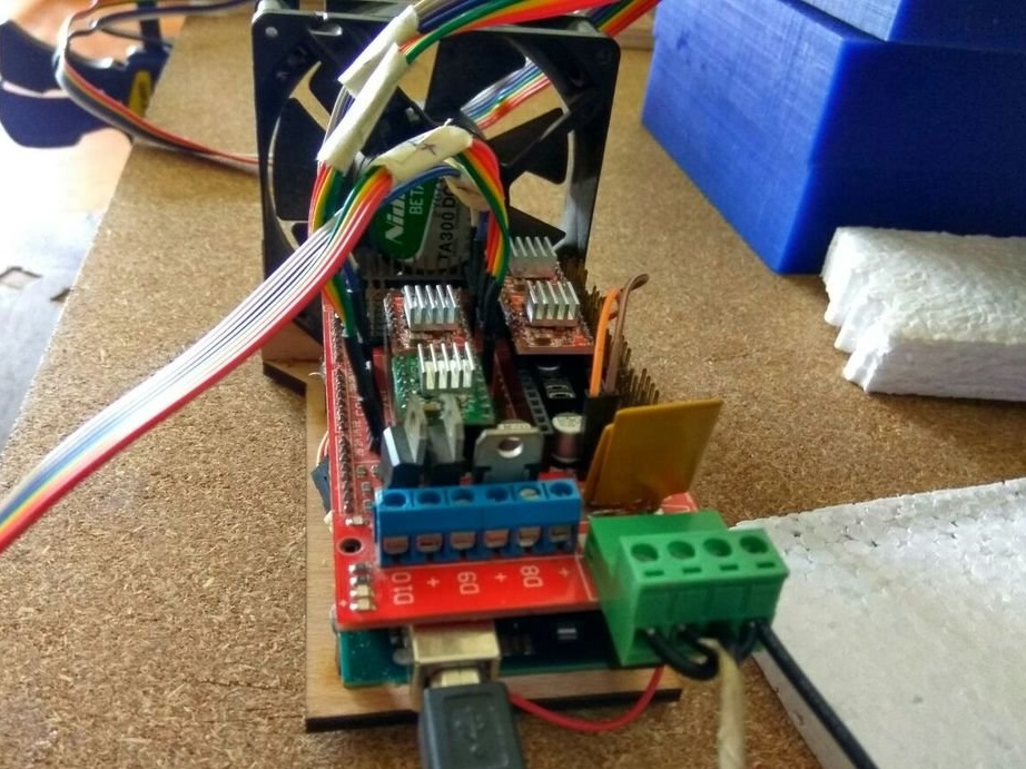
When the system is turned on, the stepper motors continue to draw current to maintain a holding position. Components such as Stepper and MOSFET drivers can become very hot during operation. Do not use Ramps without active cooling.
The master laser-cut the base for Arduino and Ramps and connected a 12V fan to provide active cooling for the board.
Step Four: Setup
Each CNC must be properly configured before starting work. Since stepper motors are used in an open-loop system (without feedback), you need to know how far the carriage will travel with each revolution of the stepper motor. It depends on the number of steps per revolution of the engine, the pitch of the spindle and the level of micro-transition that is used.
steps_per_mm = (motor_steps_per_rev * driver_microstep) / thread_pitchIt uses a stepper motor with a pitch of 200 rpm. driven by the A4988 driver at 1/16 microstep, with a lead screw in 2 mm increments.
Steps_per_mm = (200 * 16) / 2 = 1600The screw that the master used was double-sided, so the value will be half that indicated above, i.e., “800”. If the screw is four-stage, then the value will be a quarter of the above.
After flashing Mega 2560 with the Grbl8c2MegaRamps file, open the serial port monitor and enter “$$” to access the Grbl settings panel. To change any value, enter $ number = value. For example, $ 0 = 100 After setting up the machine, make sure that the machine moves the exact value as shown in the controller.
Step Five: Nichrome
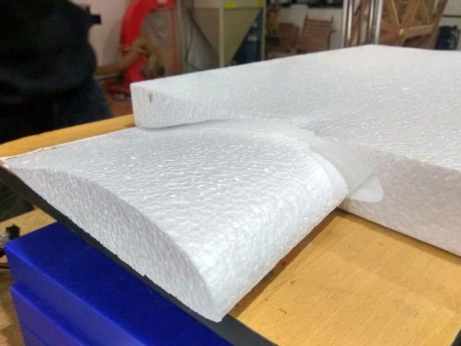
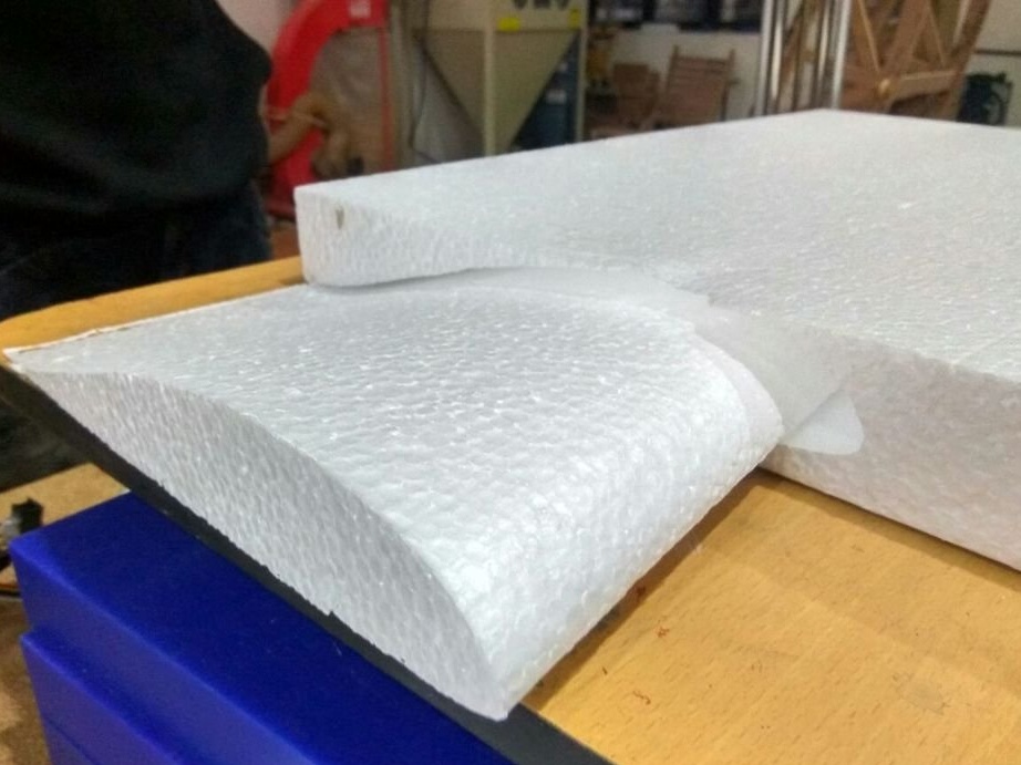
To cut the foam, you need a wire made from a suitable material that can withstand heating and will have the same temperature along the entire length.
Nichrome is a suitable material. It is best to use as thin a wire as possible to reduce grooves during cutting and to ensure clean cut lines. As a rule, the longer the wire, the greater the tension that must be applied, and the thicker the wire.
The next step is to attach the nichrome wire to the machine. Since we have 4 independent axes, we cannot just snap both ends of the wire to the supports.The wire should have some elongation, either by means of a spring, or by means of a weight attached to the ends.
Constant tension can be applied to the wire by means of a spring with constant force or a hanging weight at the end. A cheap way to get a spring with constant force is to use ID card coils.
Step Six: Software and G-Code Generation
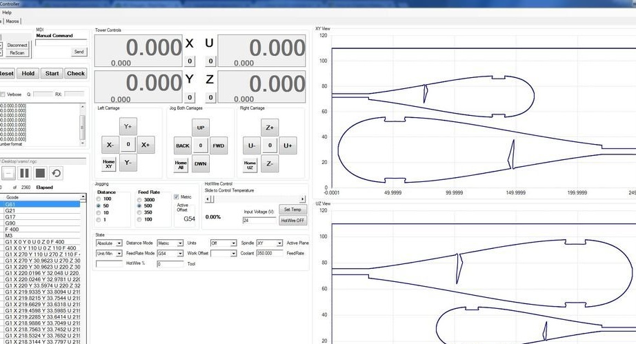
Grbl Hotwire Controller
The wizard uses the Grbl control panel, developed by Garret Visser, which was adapted for cutting by Hotwire by Daniel Rassio. The panel has independent mode control for all axes. There is also a visualization tool, a “Gcode” graph, and the ability to save your own macros. Hotwire temperature can be controlled using M3 / M5 to turn on / off and the S command “xxx” to set the output voltage, either manually or using the scroll bar in the software. The hot wire should be connected to the “D8” output and be powered by a power source connected to the “11A” input on the line junctions.
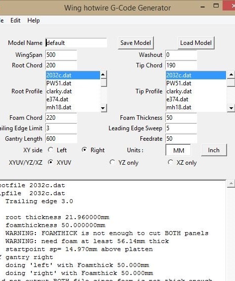
Wing g-code generator
Wing g-code generator is a program for generating the XYUV GY-code for hot cutting of airplane model wings. It runs on Python 2.7 and can also integrate with the LinuxCNC Axis interface. There is also an online version. This allows you to enter various parameters of the wing. There is a database of aerodynamic profiles in .dat format. New profiles can be imported in the same way.
This software is easy to use and supports layering the wings on the same piece of foam to save material. The output G-code can be sent to the machine through the Grbl controller.
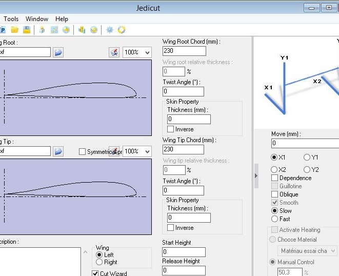
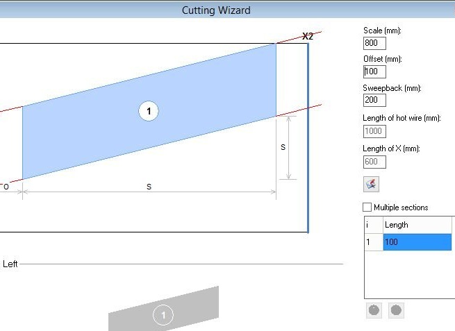
2.4 Jedicut
Jedicut - This is a cool program that can perform both CAD / CAM and perform the functions of a machine controller. There is also a plugin for generating G-code. This is not the easiest program to configure. Some of the options and error messages are in French, but if you work with it for some time, you can make it work.
Wing's G-code generates G-codes in absolute mode, which runs on Grbl without any problems, but Jedicut generates G-code in incremental mode. The master had difficulties at the first start, when the car simply moved back and forth. If this happens, edit the G-code to remove unnecessary lines in the header.
Both the Wing G code and Jedicut generate G code with some unsupported Grbl codes in the header. The controller will show on the monitor when such errors occur. Edit the G code and delete the unnecessary lines of code.
Working G-codes with both programs are included, use them to check the controller.
Jedicut.rar
winggcode.rar
Seventh step: setting the feed rate and temperature
Unlike conventional milling, wire cuts by melting foam. When the wire remains in one position for some time, the surrounding material continues to melt. This increases the groove of the cut and causes inaccuracies in size. There are two variables that affect the width of the cut.
Cutting feed rate.
Wire temperature.
The cutting feed rate is the speed at which the wire cuts through the material, preferably in mm / min. The higher the speed, the smaller the slot, but the higher the required temperature, as well as the tension in the wire should be sufficient. Good starting speeds are from 350 to 500 mm / min.
The temperature of the wire should be slightly higher than the melting temperature of the foam. The temperature is controlled by the current flowing through the wire.
There is software that allows PWM control of the wire to heat it at the right moments in order to optimize the cutting feed rate. The temperature of the wire is determined by the square of the current times the resistance.
There is a special calculatorwhere you can make all the necessary calculations.
Step Eight: Machine Operation
The process begins with a design that is exported as a DXF file. This file is then imported into the CAM software and output as a G-code. The machine is turned on and calibrated. The material is placed on a workbench and the starting position is set. Run the G-code file and see how the device does all the work for you.
According to the master, the machine is easy to manufacture and facilitates the work of aircraft models.

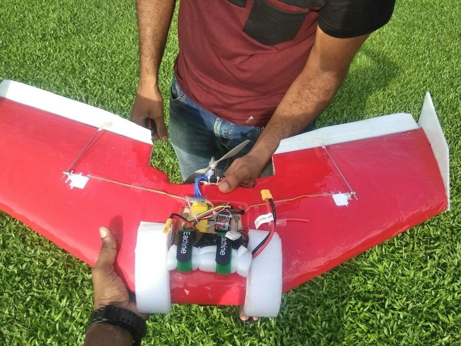
In the video below, you can see an example of the machine.