The light doorbell is convenient for the deaf, in noisy rooms, and also vice versa, when silence is required. The author of Instructables under the nickname DIY Hacks and How Tos developed a rather successful design of such a device. Here the master takes the case:
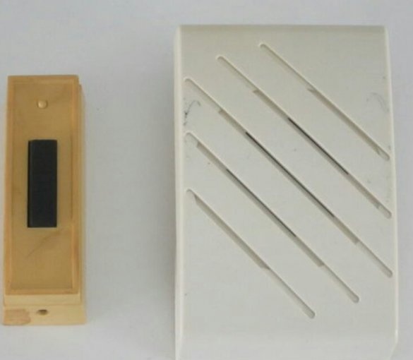
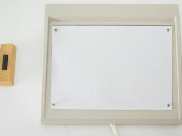
Wireless doorbell with button-powered battery and main unit mains power:
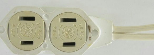
Outlet:
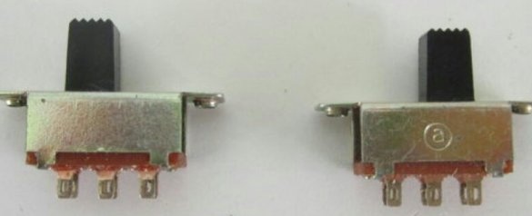
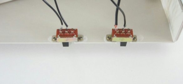
Two switches:
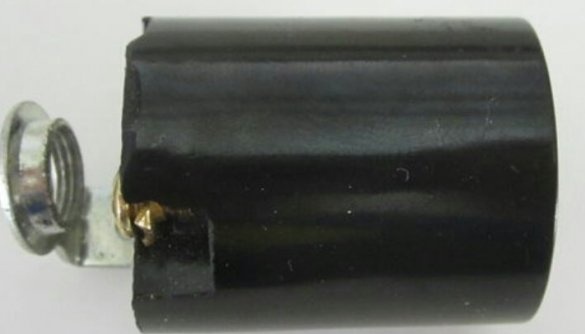
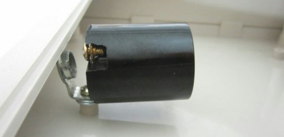
Lamp holder:
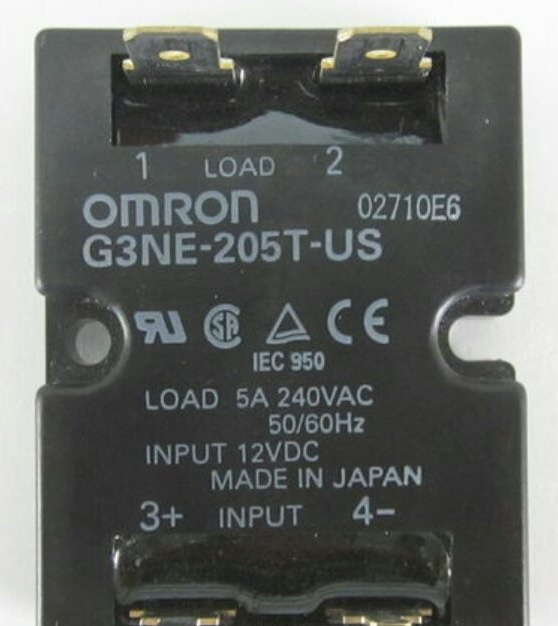
Solid state relay:
And a control board that has not yet been assembled:
The master opens the main call block:
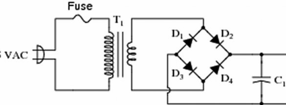
And it finds there, among other things, a transformer power supply (if you have a call with a damping resistor or capacitor instead of a transformer, then it will not work for this alteration).
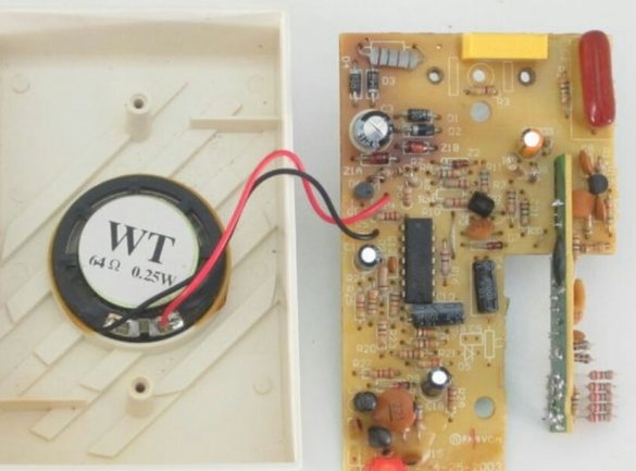
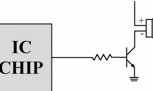
And also a transistor key through which the musical microcircuit controls the dynamic head:
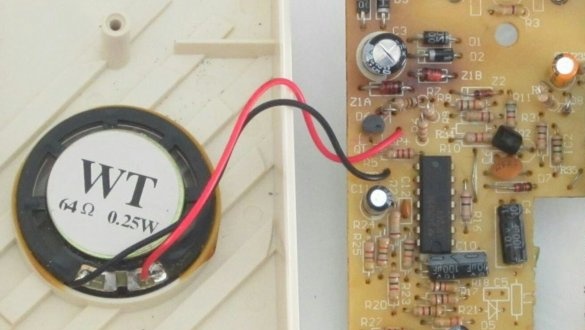
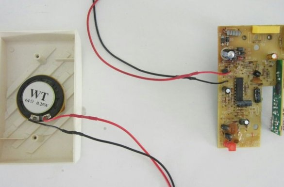
And now, as they say, watch your hands. Here is the board, here is the dynamic head:
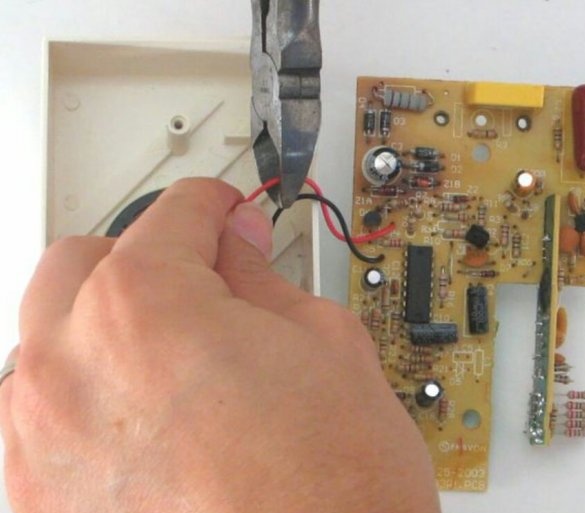
The master bites both wires going to her:
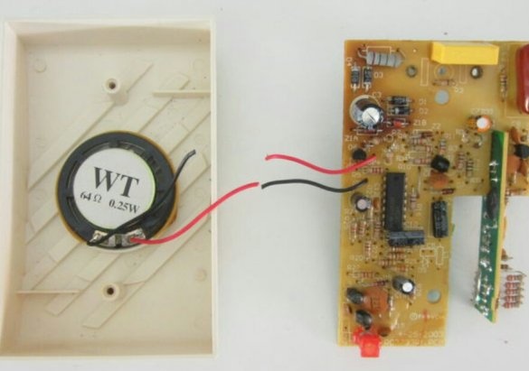
There were two, four became:
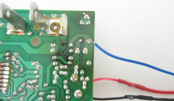
Their master lengthens by insulating the joints with heat shrink:
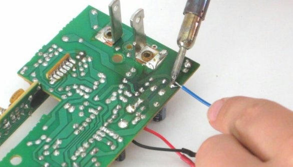
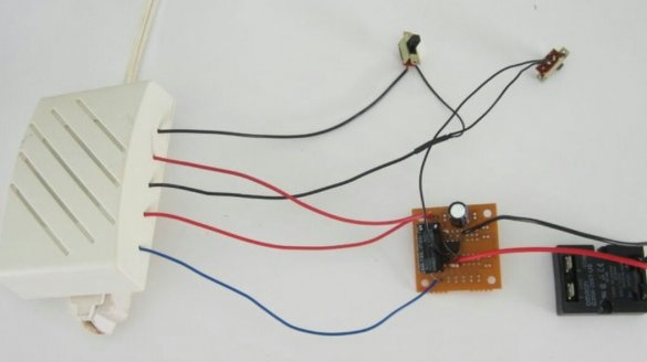
So, four wires are drawn, of which two are from the dynamic head, one is from the plus power, and another is from the collector of the transistor. What is missing for complete happiness? Common wire. The master outputs it from the negative output of the BP filter capacitor, but it is also possible from the emitter of the same transistor - this is the same printed conductor.
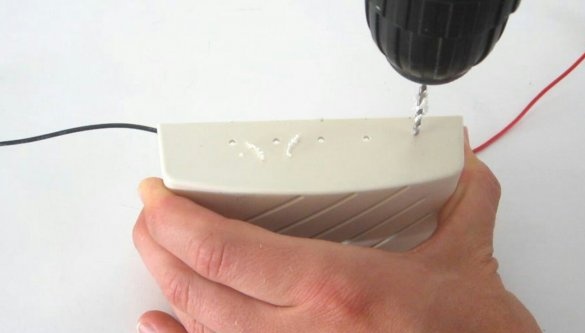
Now there are five conductors brought out, the master drills the same number of holes in the bell case:
Threads conductors through them and closes the call:
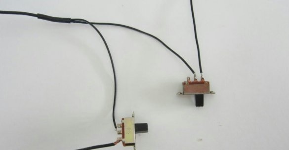
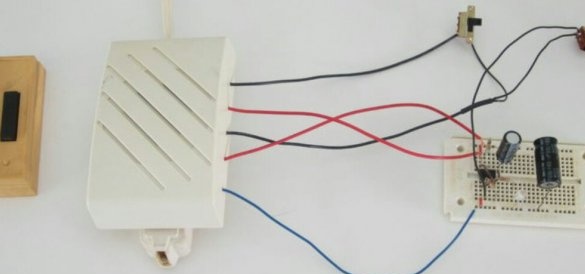
Adds two switches. One - to connect the dynamic head as before. The second is to send a signal from the collector of the transistor to the control board through it:
With two bits, as you know, four binary numbers can be set: 00 - everything is off, 01 - sound mode is on, 10 - light mode is on, 11 - both are on
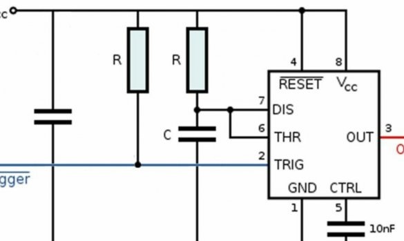
And it adds to it a capacitor in parallel with the power supply and a load resistor for the transistor switch, necessary when the dynamic head is turned off and the control board is connected (mode 10 in the binary system).
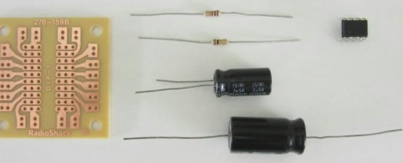
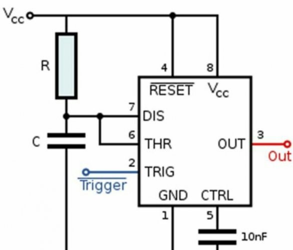
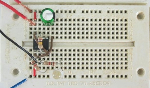
The power capacitor is 330 microfarads, the timing capacitor is 100 microfarads, the load resistor is 1 kOhm, and the timing resistor is 100 kOhm. The rated voltage of the capacitors is not lower than the voltage at the PSU output, and since they are electrolytic, it is necessary to observe the polarity when connecting them. The wizard debugs the control scheme on a breadboard type breadboard:
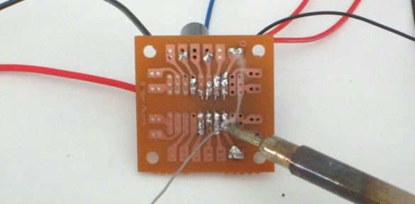
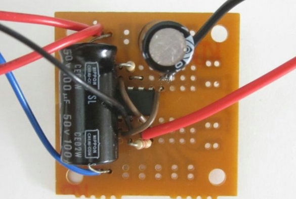
And transfers to a universal printed circuit board:
Connects, observing the polarity, the input of the solid-state relay between the output of the control board and the common wire:
Shows the relay near:
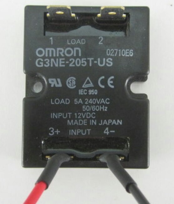
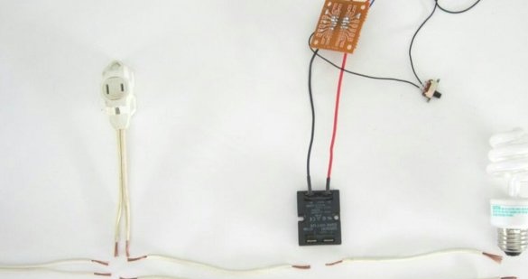
Prepares the conductors for connecting the outlet to the cord with the plug directly, and the lamp holder - through the optosymistor of a solid-state relay:
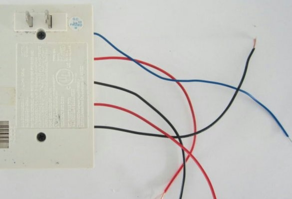
Performs all connections, again shows the relay near:
Soldering the conductors to the relay terminals is inconvenient, therefore the master uses connectors similar to the FIR:
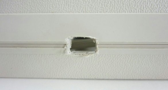
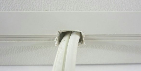
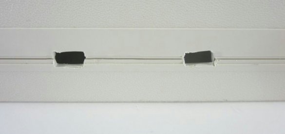
"In principle," everything works, the master makes it work in the case. Cut a small notch, displays a power cord through it:
He makes two more notches for the switches, but so far he has not put them there:
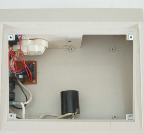
Secures the lamp holder:
Installs in place a board and outlet, which includes the main unit of the call:
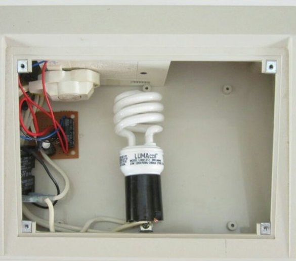
Screws in a compact fluorescent lamp. The article was written in 2014, since then LED lamps have fallen noticeably, so now it is better to use LED lamps.
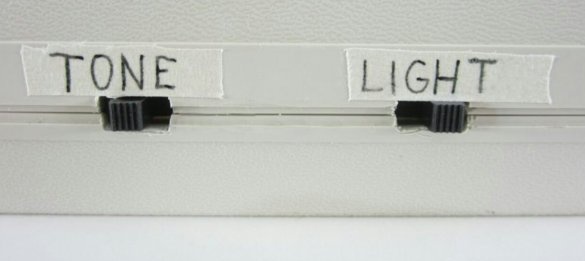
Sets the switches in place, indicates their functions:
Closes the case with a matted plexiglass rectangle cut to size:
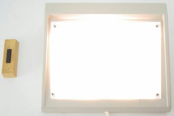
Checks ready light call. Thanks to the single vibrator, the light does not turn off immediately after releasing the button. And without it it would be the same, because the musical microcircuit in the call still plays the melody completely.
Some wireless doorbells have channel switches and allow the operation of several main units from a single button. Then you can collect several of these devices and place them in different rooms (hallway, kitchen, room) to notice the light signal, being in any of them.

