From this article, you will learn not only how to create simple wooden LED panels of various shapes, but also how to design a low-voltage lighting system with touch buttons made of walnut. Using the buttons you can turn on, off, and also reduce the brightness of the luminaires. This lighting system was made for a one-room apartment, but can be adapted to any home.
Let's see two small videos.
Tools and materials:
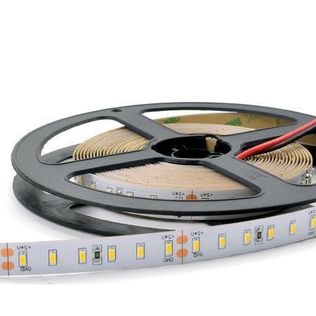
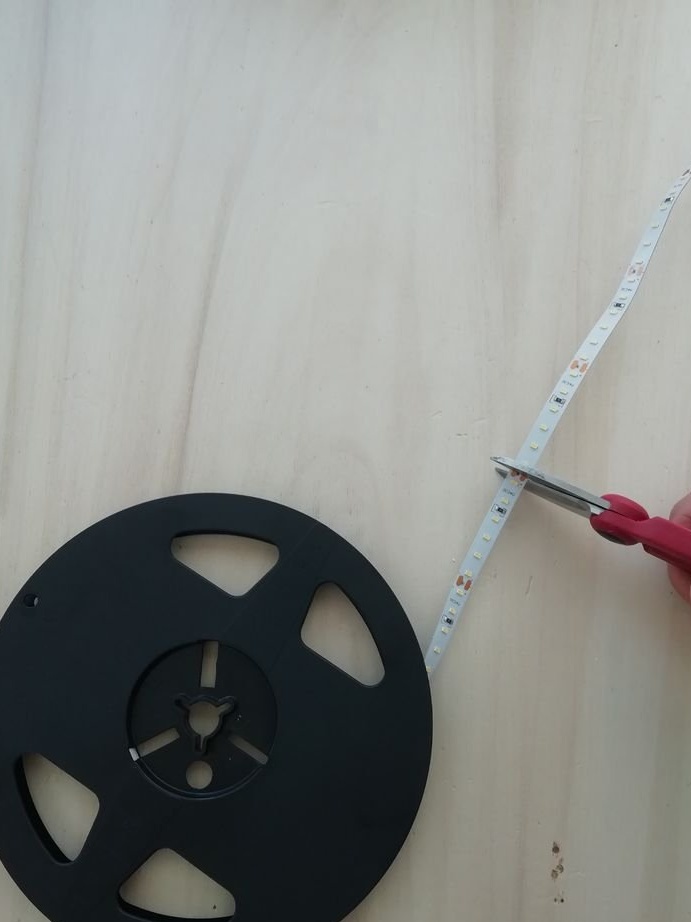
-LED strip 24;
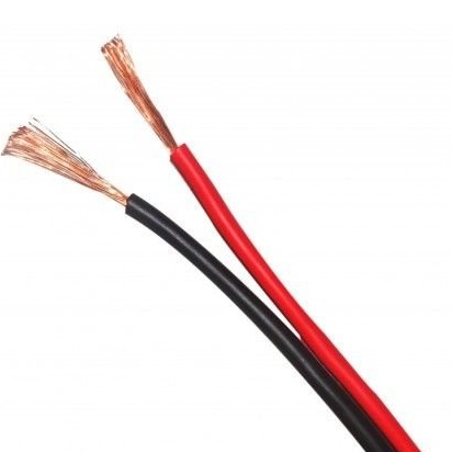
-Wire;
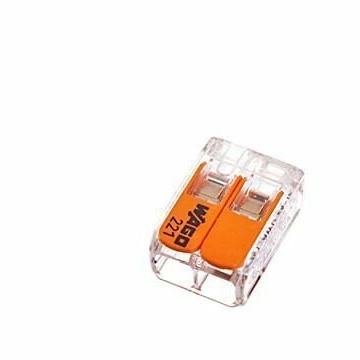
-Connectors;
-Aluminum sheet;
-Rail;
-The cloth;
Neodymium magnets with a hole;
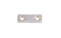
-Metal strip;
-Bracket;
-Fasteners;
-Board;
- Brass plate on / off;
-Diffusers;

Step One: Lighting Design
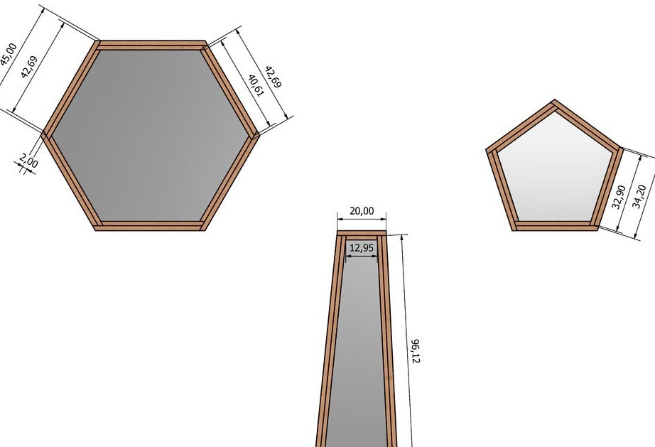
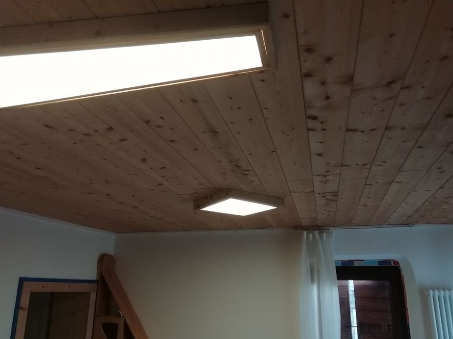
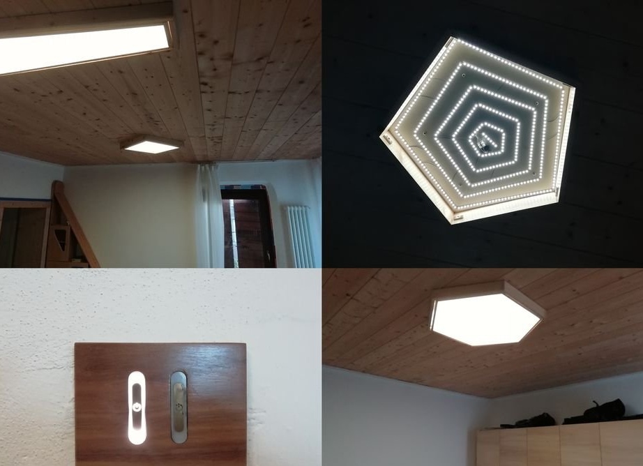
The master decided to design the panels of the following 4 basic geometric shapes:
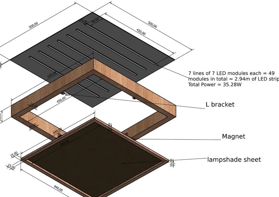
- square and trapezoid for lighting the kitchen and living room
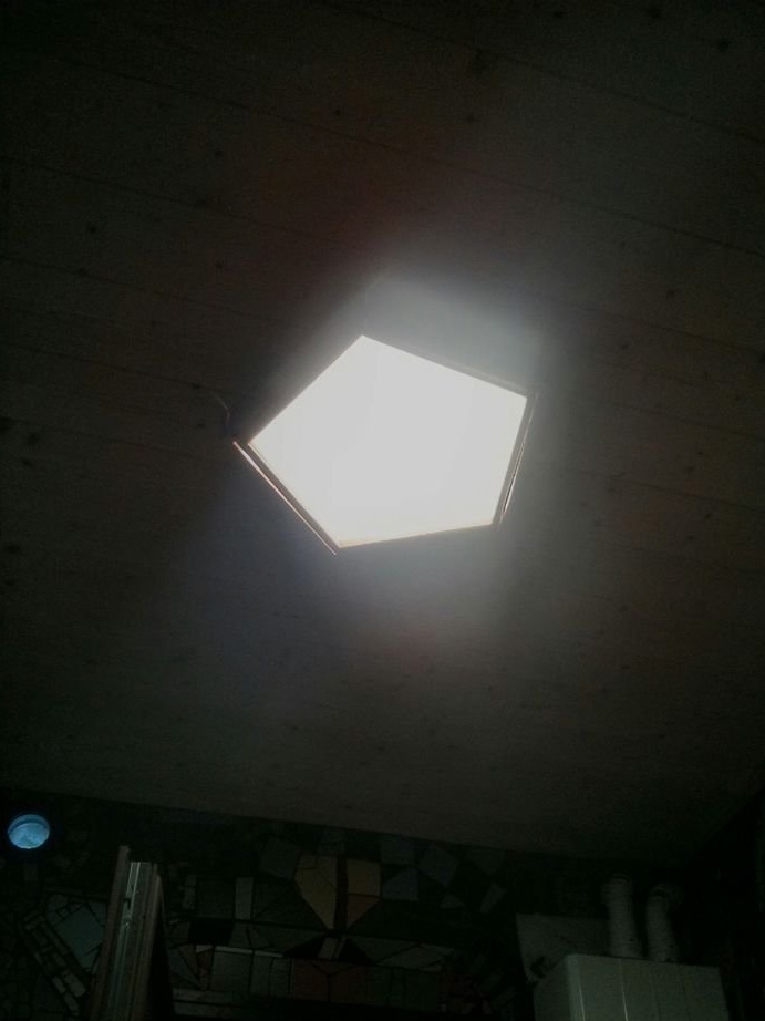
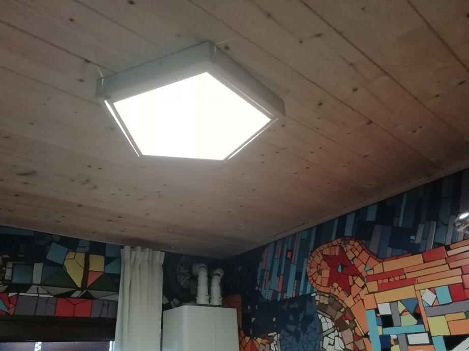
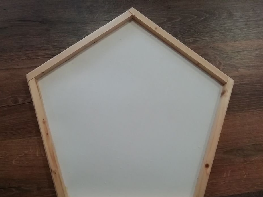
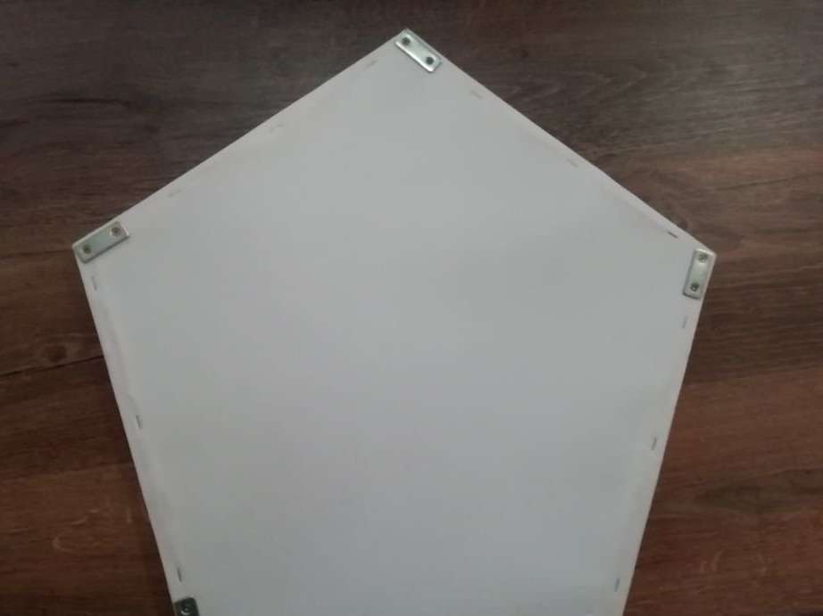
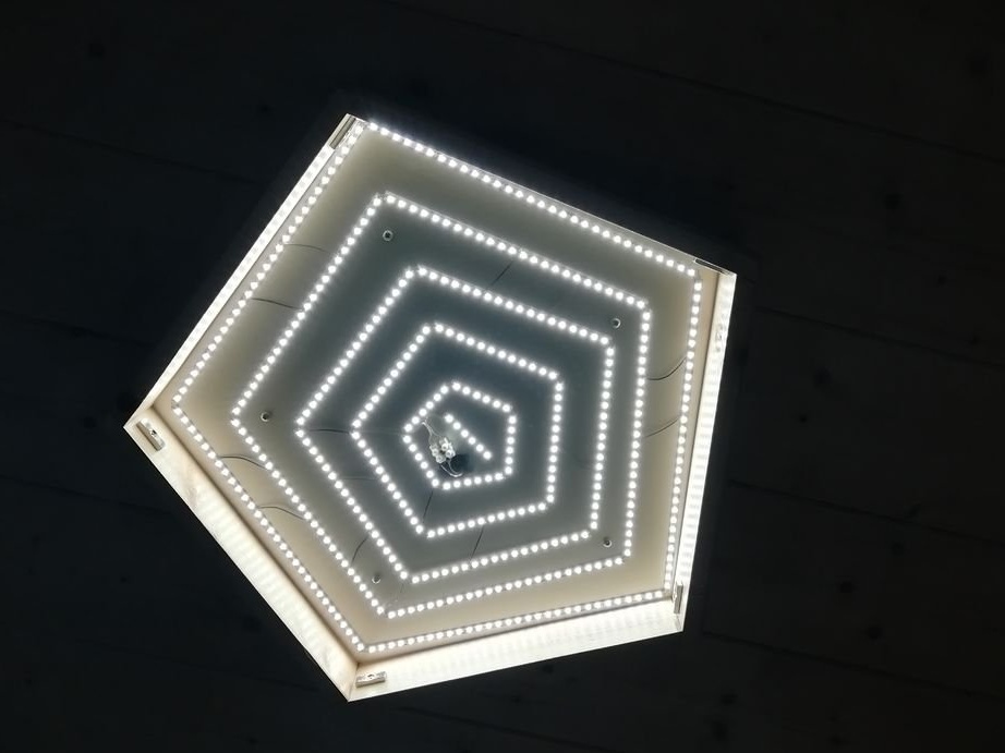
- pentagon for lighting the bathroom
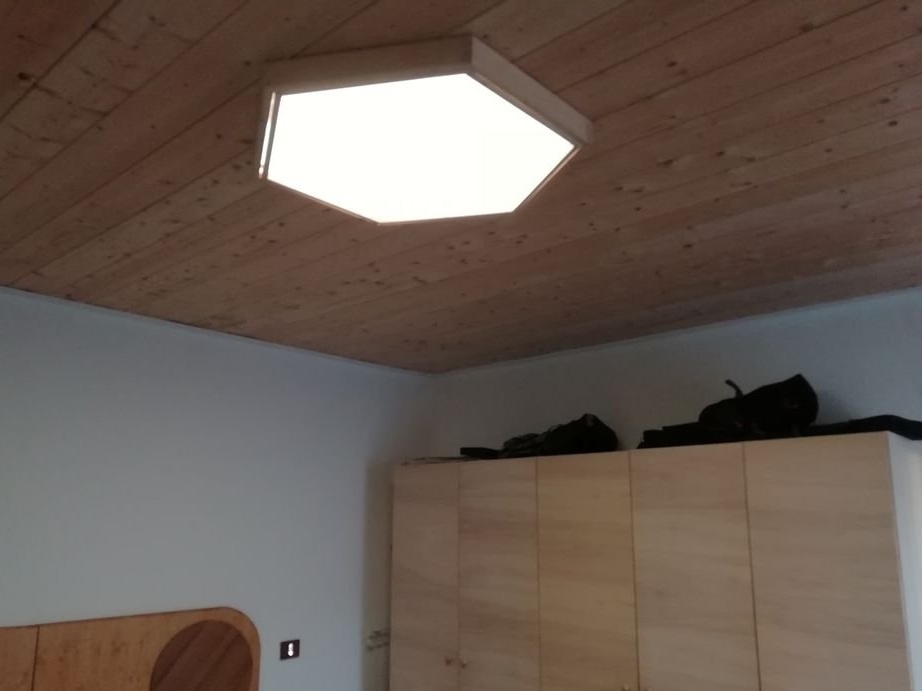
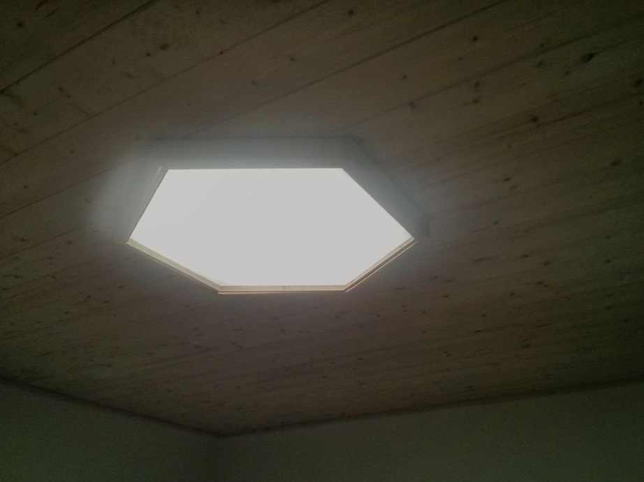
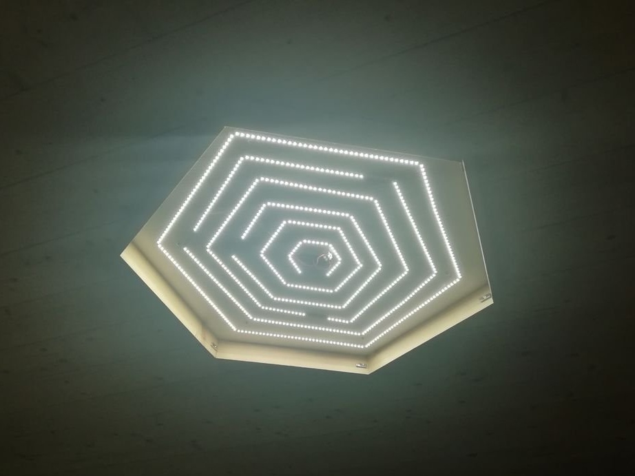
- hexagon for bedroom lighting
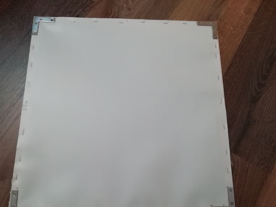
To access the LEDs, the outer frame will be attached to the main frame with magnets. The base and radiator of each panel is an aluminum plate.
Details the master cut on a CNC machine. Files for downloading are available below.
panels-wood-dimensions-building.dwg
panels-wood-dimensions-building.pdf
aluminum_cuts_dimensions.dwg
aluminum-sheet-dimensions.pdf
panels-idea-design.pdf
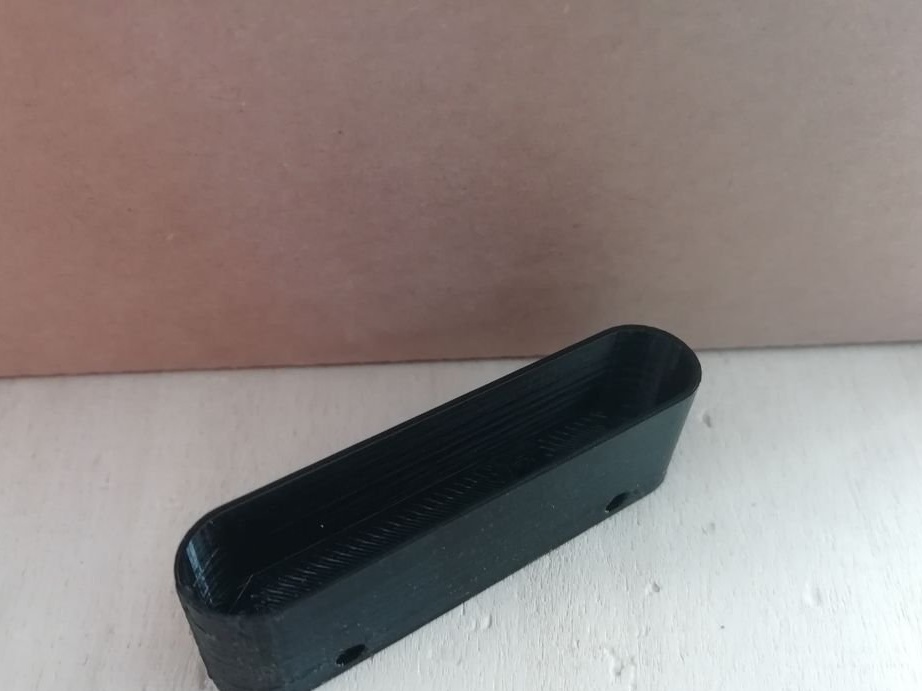
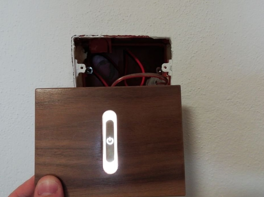
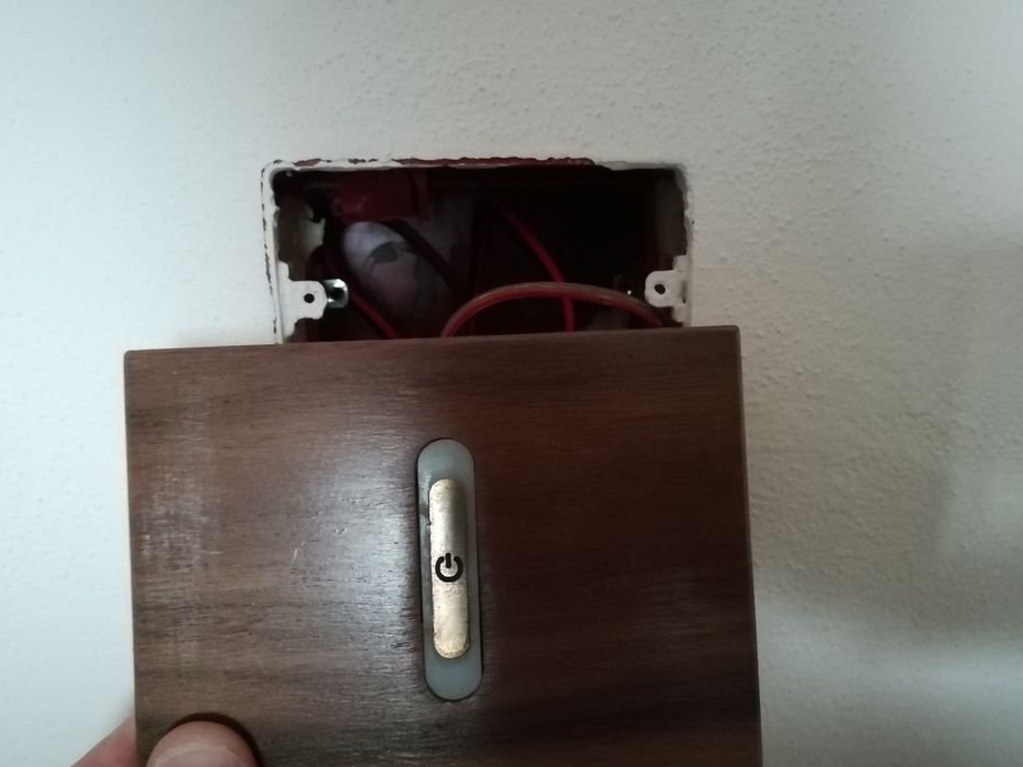
Step Two: Switch Design
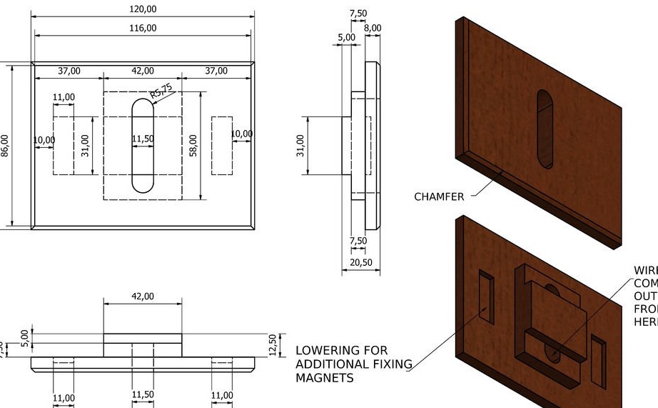
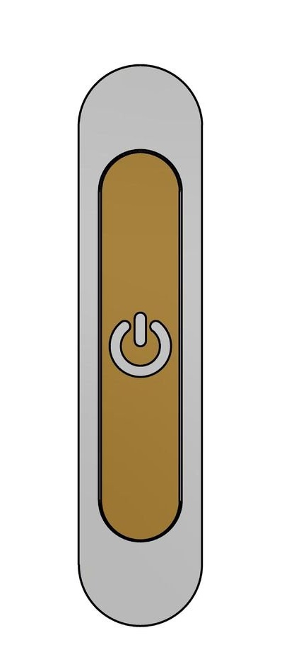
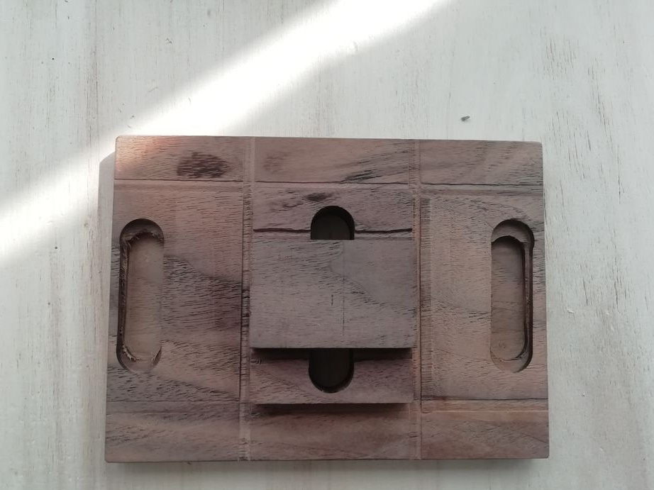
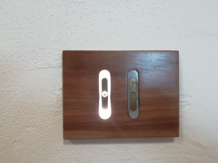
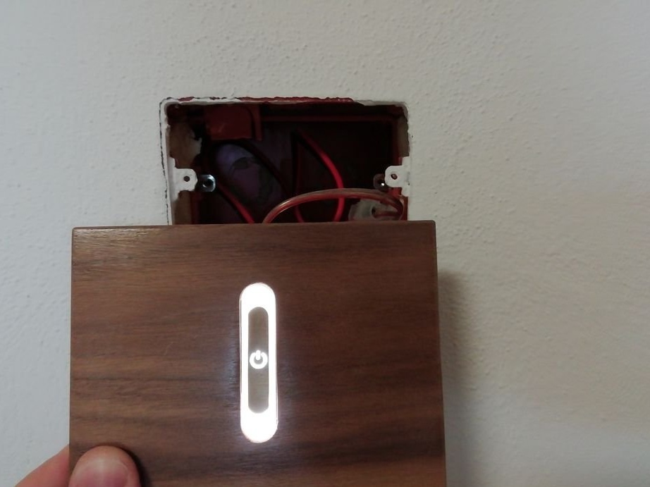
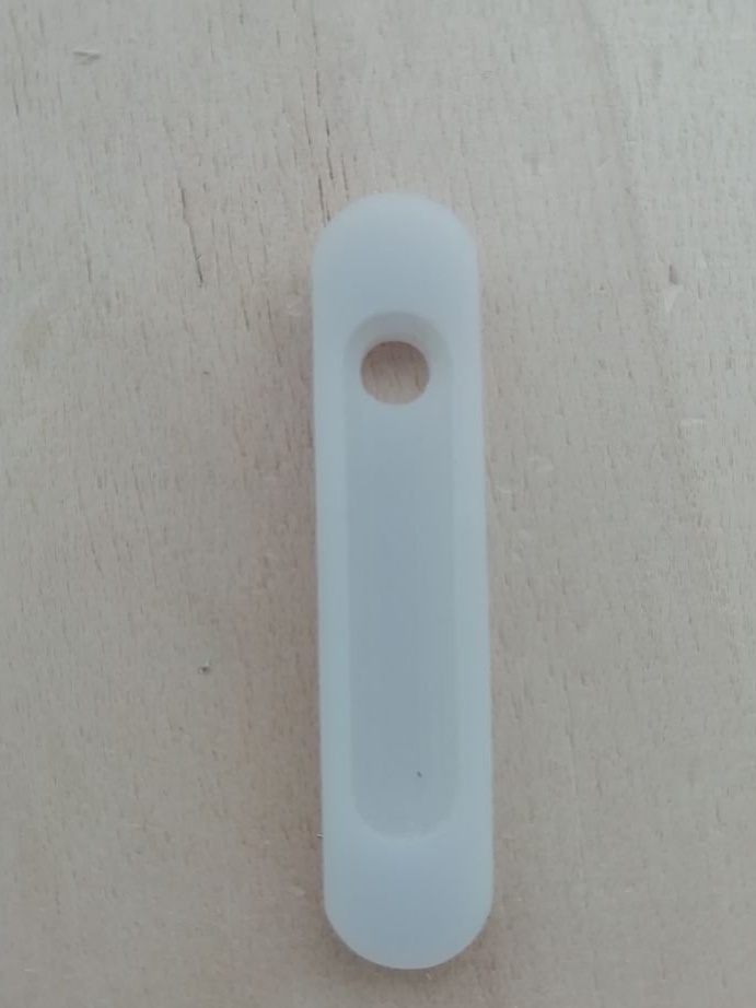
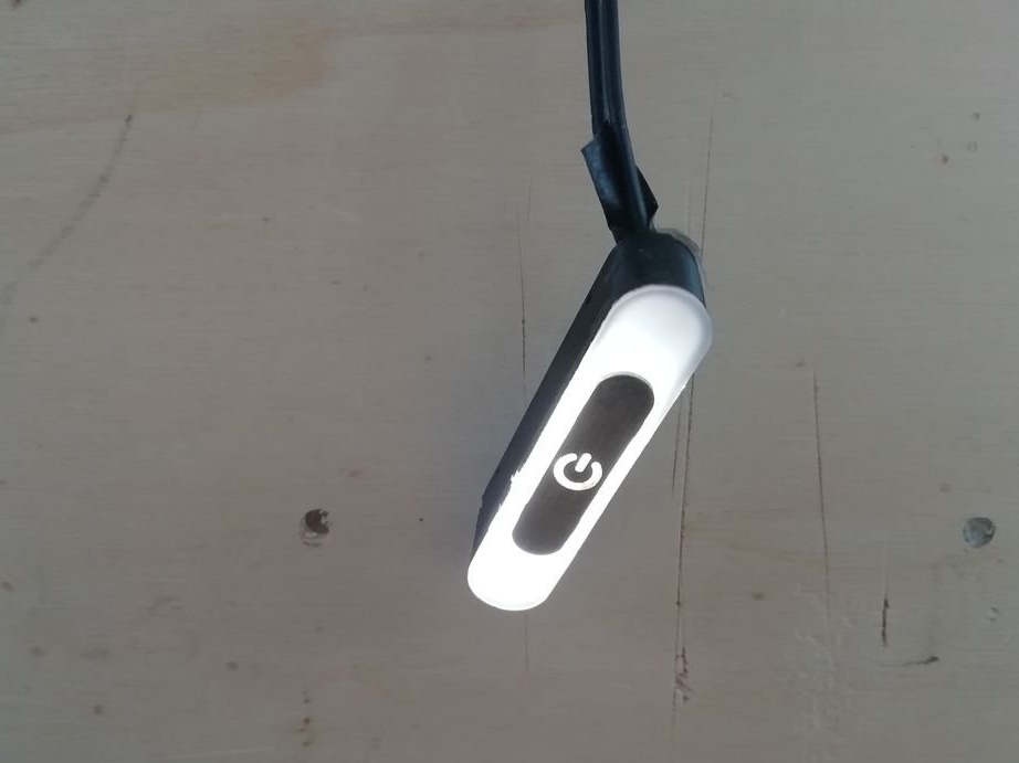
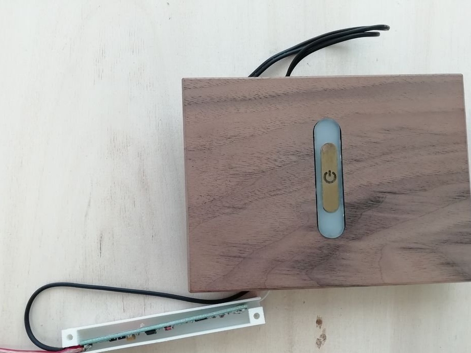
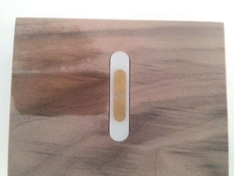
When developing switches, the master was faced with the task of making them stylish fit into the design of the rooms. Touch buttons are installed in a wooden base. The buttons are backlit and diffuser.
The master has developed two types of switches, with one and two buttons. All files for downloading are available below.
Touch_assembly.x_b
Touch_button.pdf
wood_support_one_touch_button.pdf
wood_support_two touch_buttons.pdf
circuit-case - & - lid-3D.stl
touch-case.stl
Cover-diffuse-back.dxf
brass-on-off.dxf
Cover-diffuse-front.dxf
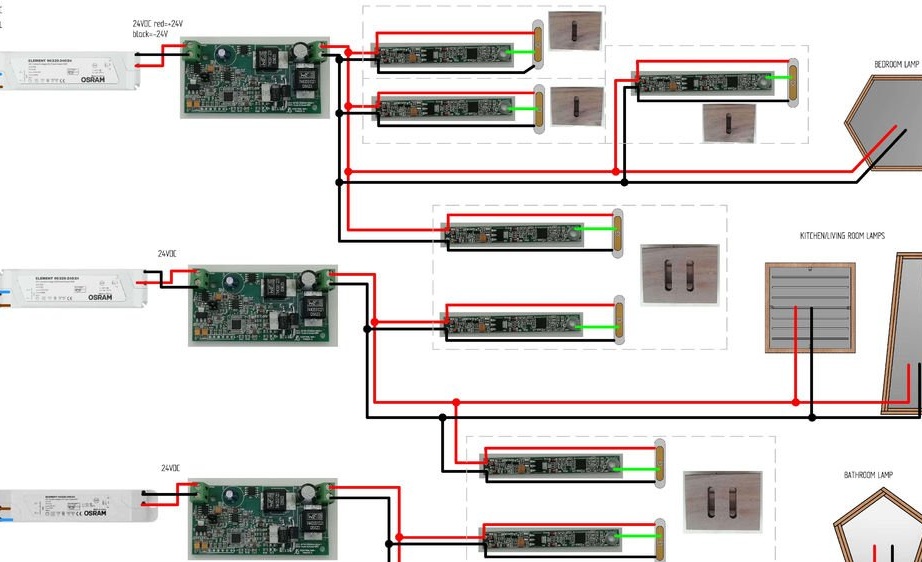
Step Three: Wiring Diagram
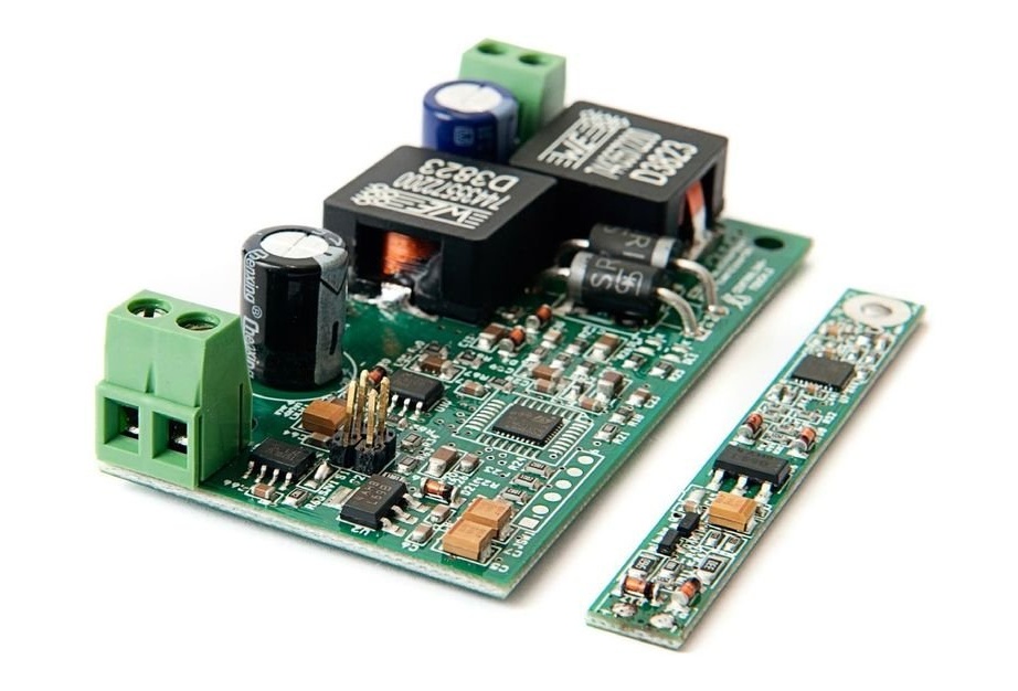
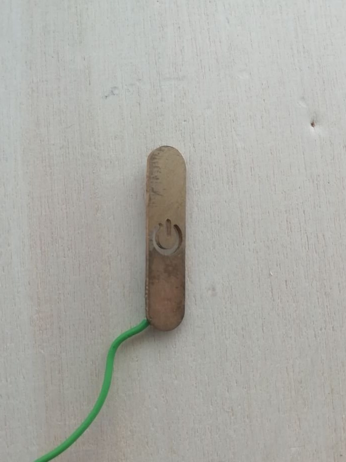
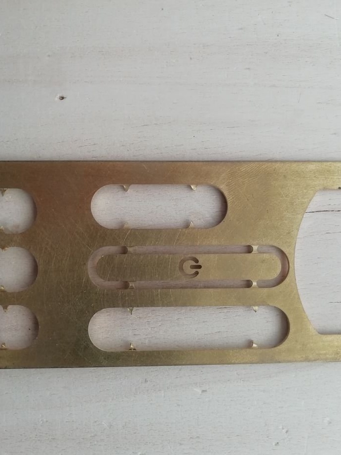
Systema works in such a way that if the user touches any of the sensor sensors connected to the 2-wire 24 V bus, all 24 V LEDs on this bus will turn on, and if the user presses the sensor for some time, it darkens all the connected lamps and buttons. The capacitive zone of each sensor was connected to a brass plate with the on / off logo, this is the place that the user must touch to change the lighting.
As can be seen from the diagram, the master dashed out all the switches with dashed lines.Some of them are single-key, some are two-key.
illumination_system_wiring.pdf
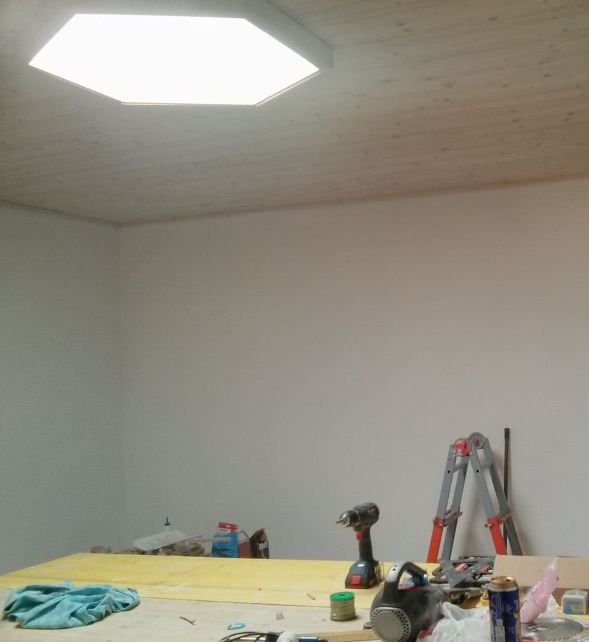
Fourth step: making fixtures
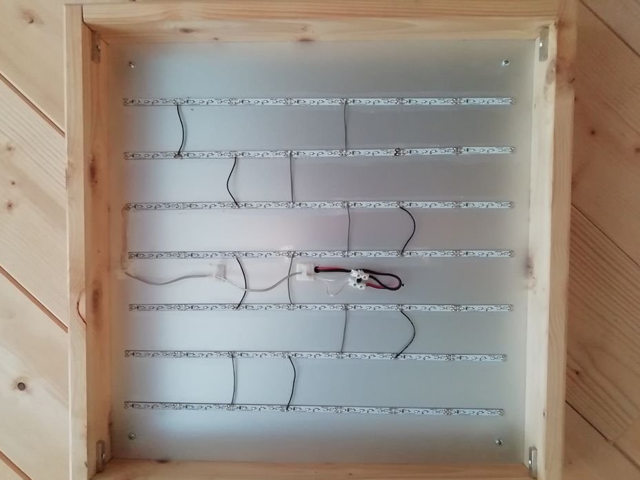
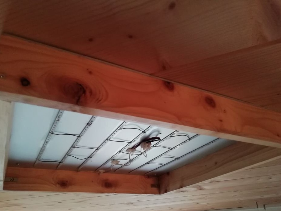
To assemble the panels, you first need to cut the bases of aluminum with a thickness of 2 mm. File edges to file. Then a wooden frame is made and an aluminum plate is attached to it. An LED strip is glued inside the frame.
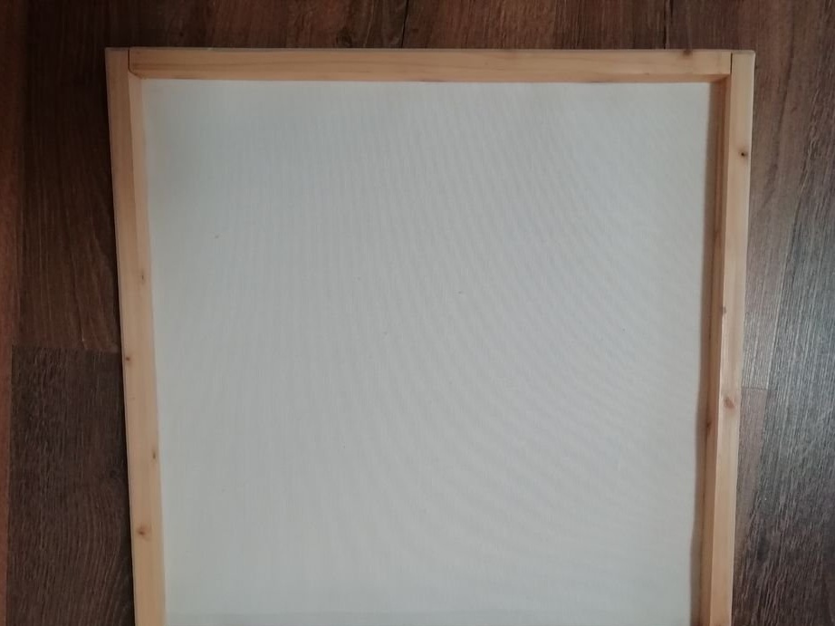
As a lampshade, the master uses a suitable fabric fixed to a wooden frame. As previously written, the lampshade is mounted on the lamp with magnets.
Step Five: Making Switches
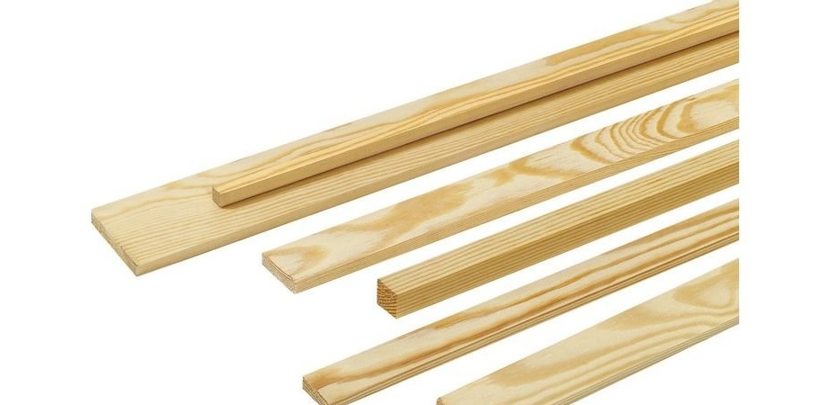
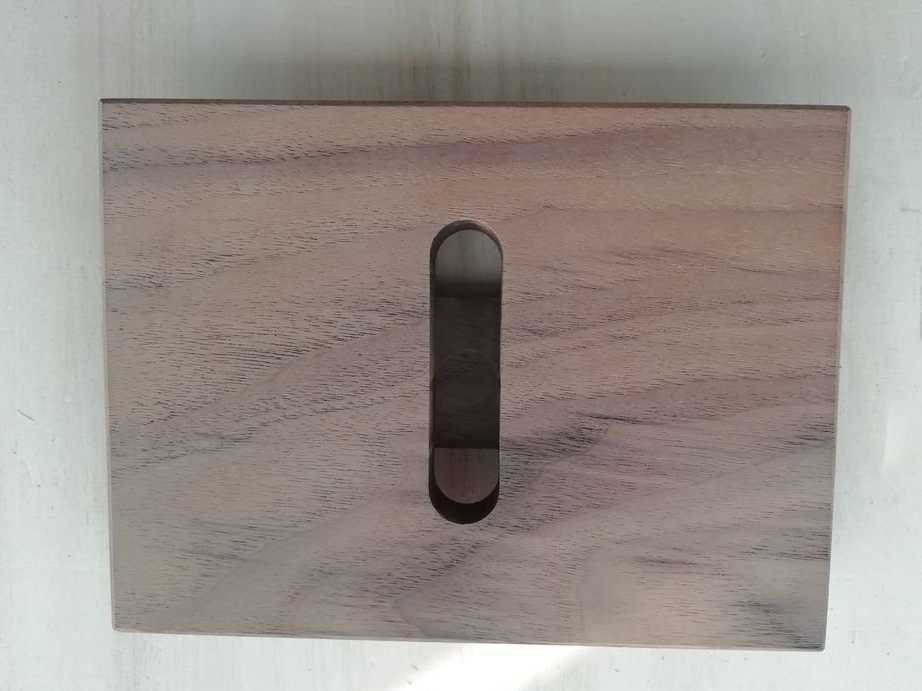
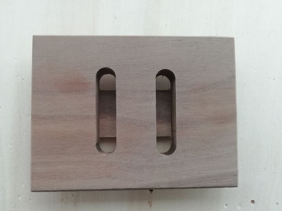
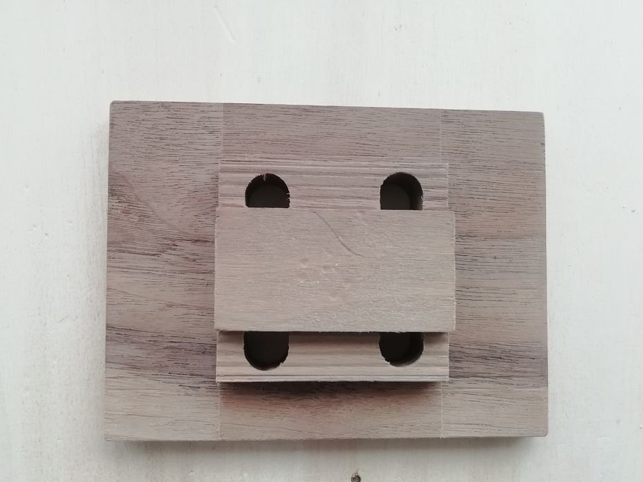
For the manufacture of switches, the master decided to use walnut planks.
The switch can be made manually, or, with access to the CNC machine, cut on the machine.
The master processes the finished parts by impregnation.
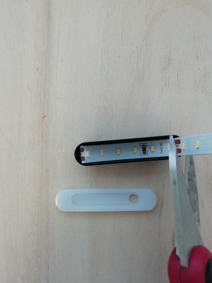
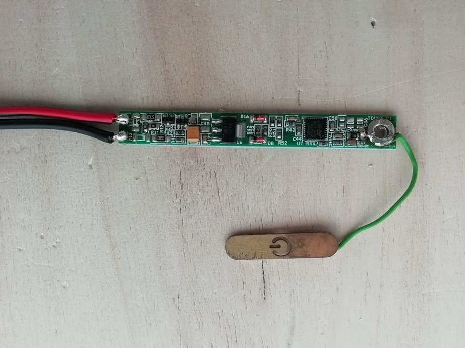
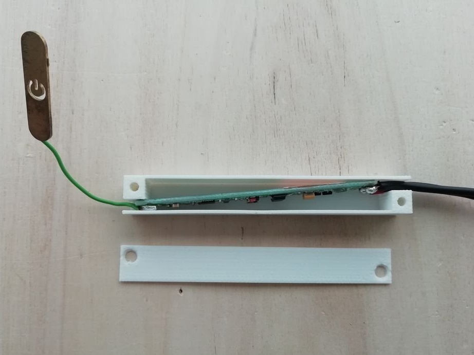
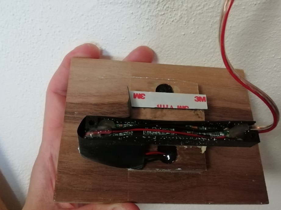
If all the parts are present, the master proceeds with the assembly. Solder two wires to a 24 V LED strip. Usually the red wire is positive, and the black wire is negative. Solder the wire to the brass plate. Adheres the diffuser to the body. Solder the wires to the terminals of the Systema sensor circuit board, as shown in the diagram. It places the Systema sensor in a housing specially made for it. Installs the cover. Connects the sensor to the lighting system.
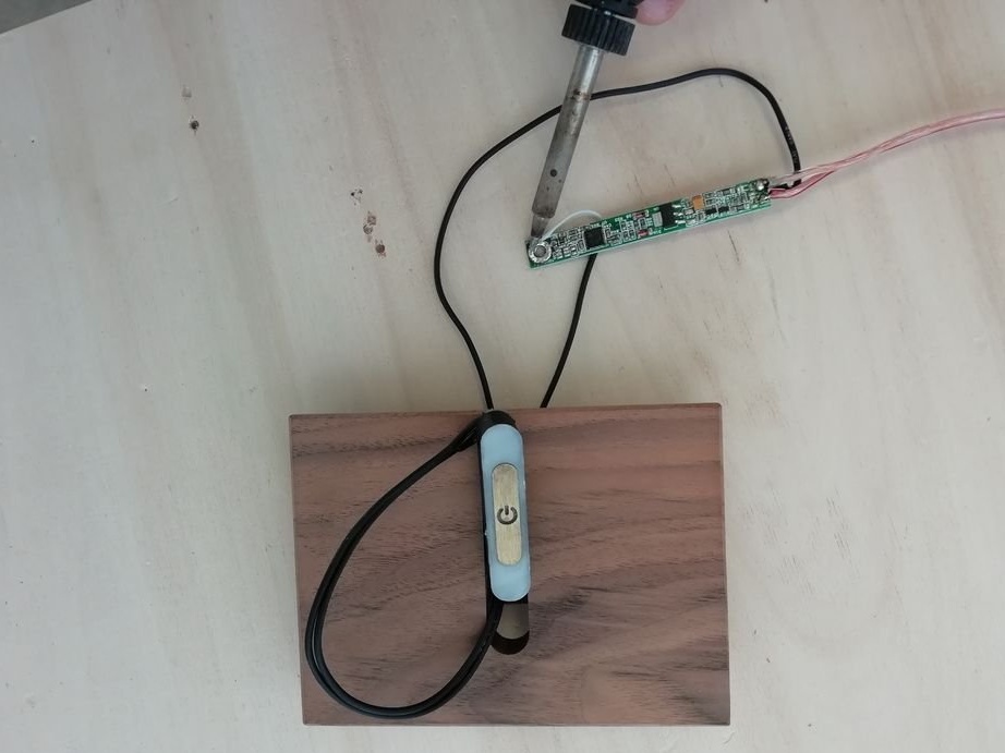
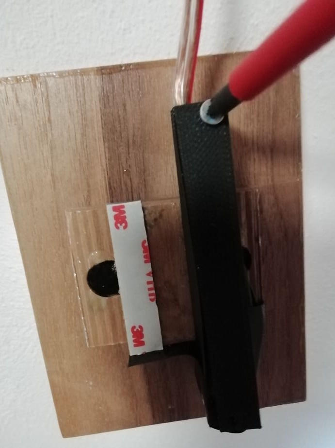
To check the touch button, follow the steps shown in the video: connect it to the Systema control unit and apply power (24 V).
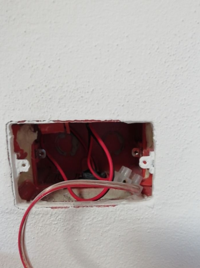
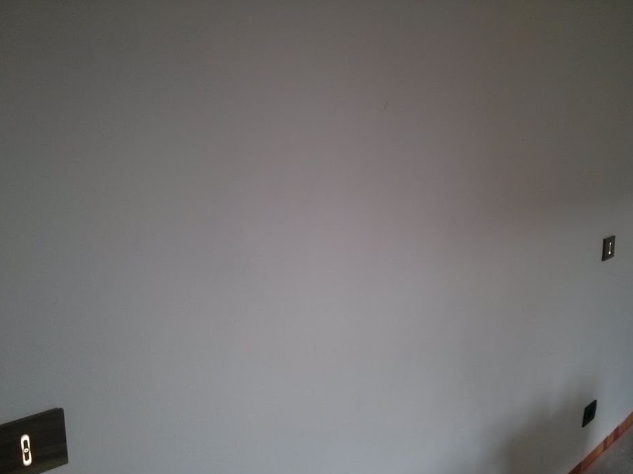
Step Six: Connect
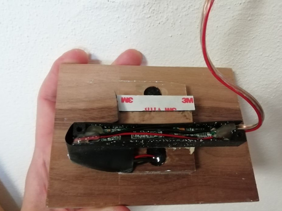
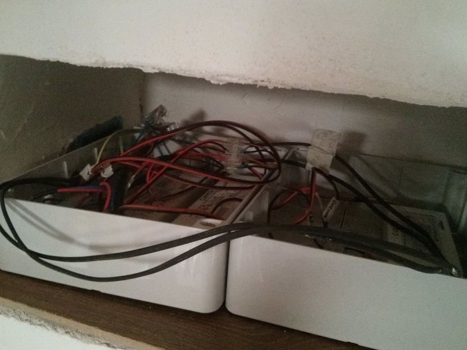
Next, the master connects and installs the switches in the sockets. Installs lights and power supplies. Power supplies need to be selected 20% more powerful from the calculation. The master calculated the power supply for the fixtures of each room.
Kitchen / living room → 35 W (square) + 35 W (trapezoid) = 70 W → 90 W Power supply
Bedroom → 75W (hexagon) → 90W power supply
Bathroom → 43 W (pentagon) → 60 W power supply
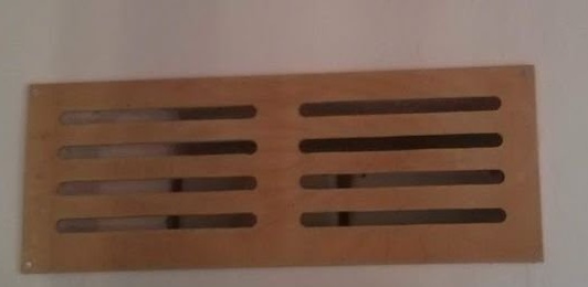
The master installed all the power supplies in one niche and closed it with a decorative grill.

All is ready.