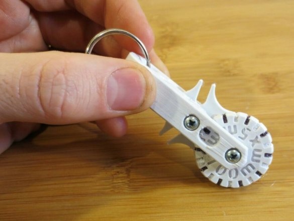
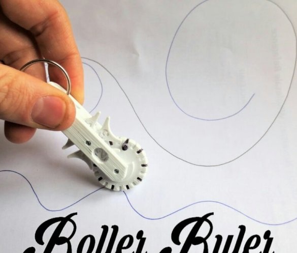
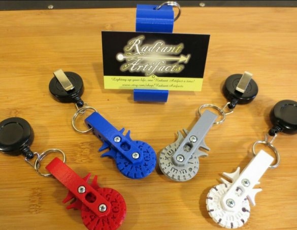
The author of Instructables under the nickname MechEngineerMike talks about the curvimeter, assembled mostly from 3D-printed parts. The following are several such curvimeters, as well as the finished component used in them - a badge on a roulette (the badge itself must be removed, leaving only the roulette).
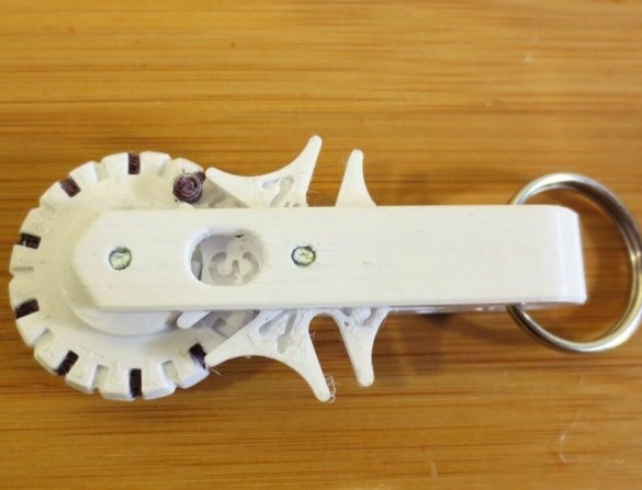
And this is an example of application homemade:
Depending on which of the two rollers you print, one division on it corresponds to 5 mm or 0.25 inches, one revolution to 100 mm or 4 inches, the built-in single-digit mechanical counter counts up to 5 revolutions, which corresponds to 500 mm or 20 inches . The .stl file for the millimeter version of the movie lies herefor inch here. There are also print files corps and counter.
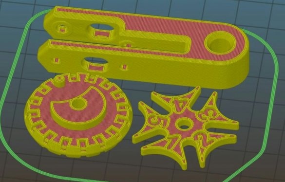
Printing parameters: Platssmass - any (except flexible), nozzle diameter max. 0.4 mm, layer thickness max. 0.2 mm, at least two perimeters on all sides, bottom and top, filling at least 10%, the printing time for all parts is about 2 hours, their location when printing is as follows:
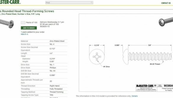
You will also need two such screws (the choice of the supplier is not critical, the main thing is the parameters, the screenshot of the wizard gives an example):
The use of a roulette from a badge is optional, but will make using a curvimeter more convenient. After printing, it is necessary to drill holes in the roller and counter with a 3.5 mm light, then remove the burrs in these holes, and also file the case surfaces in contact with the rotating parts. Then assemble the curvimeter with two self-tapping screws and, if desired, attach a tape measure. Do not overtighten the screws, otherwise the roller and rev counter will not be able to rotate.
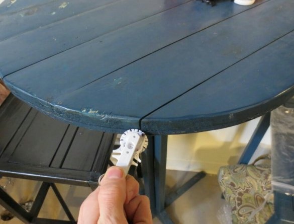
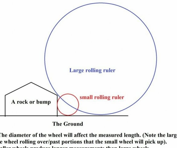
The following illustration clearly shows why, if there is any protrusion or other obstacle at the beginning or end of the measured curve, a curvimeter with a roller of a smaller diameter will measure the length more accurately:

