
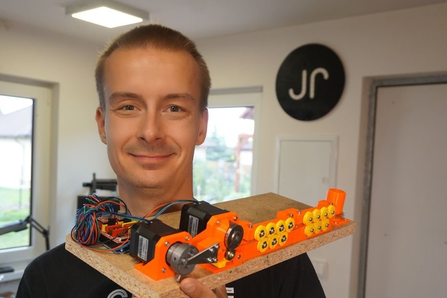
An interesting device was invented and manufactured by the Master, this is an apparatus for bending wire of any shape. Making springs is one of its features. This machine is capable of bending 0.8 / 0.9 / 1 mm wire into any 2D shape.
The main objective of the manufacture of this machine was to automate the bending process. Other homemade machines are not very accurate, and their bends have a fairly large radius.
The second task was to make it as simple as possible using commonly available parts and components. Some parts of the machine are printed on a 3D printer, and metal parts can be purchased at the store.
What is the master for such a machine for? He is interested in making LED figures, snowflakes, stars, flowers, etc. In their manufacture identical parts from wire are needed, and this machine will facilitate their manufacture.
Let's watch a short video with an example of the device.
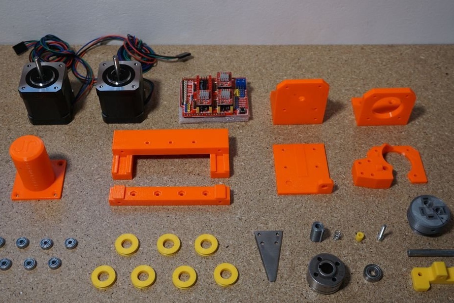
So, for the manufacture of such a machine, the master used the following
Tools and materials:
-3D details (print files can be downloaded here);
-Fasteners;
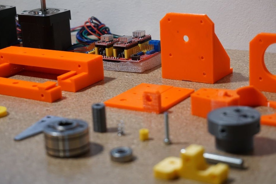
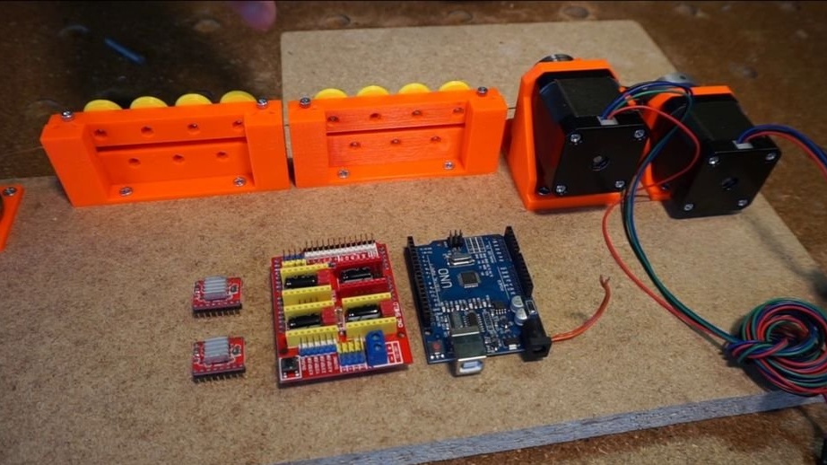
-Arduino UNO;
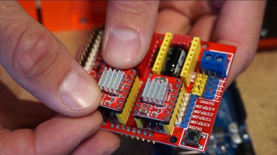
-Expansion board for Arduino UNO;
-Step driver A4988 -2 pcs;
-Step engine NEMA17 -2 pcs;
-12V 3A power supply;
- wire feed mechanism;
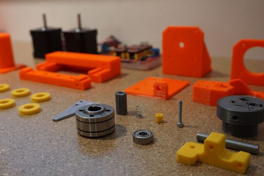
-Steel spring 4x6 mm;
- Bearing 3x10x4 mm;
-Bearing 6x15x4 mm;
-6 mm steel rod;
- Steel sheet 2 mm thick;
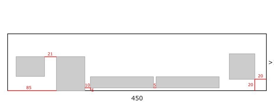
-Wood board for the base 450x100 mm;
-Screwdriver;
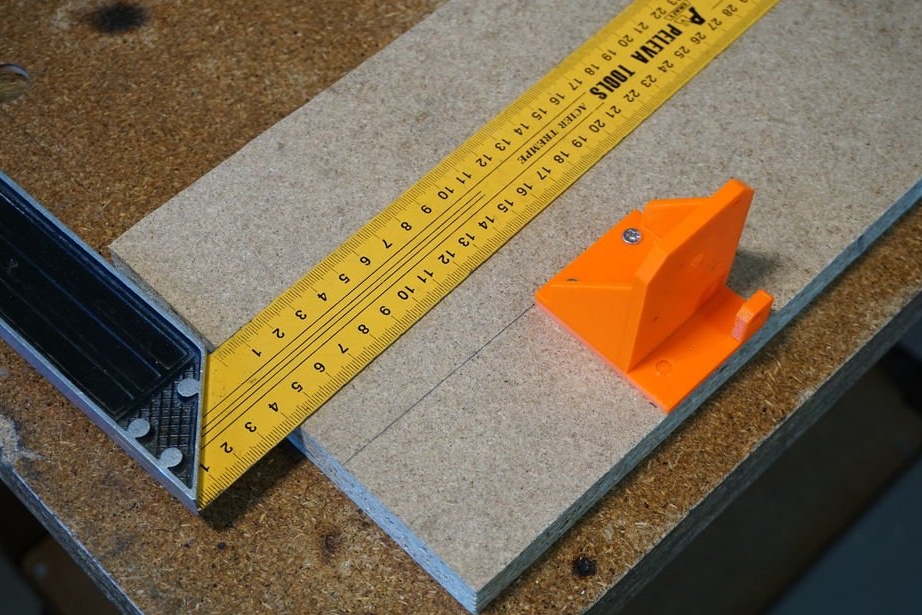
-Gon;
Step One: How It Works
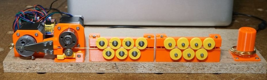
Let's look at how the machine works (from right to left).
Spool holder - it holds the spool of wire for processing the machine.
Rectifier - a set of 7 rollers so that the wire is as even as possible. Working with straight wire is crucial. That is why two rectifiers.
Broach - you can find a similar mechanism in your 3D printer. A set of gears pulls the wire from the reel through the rollers and pushes it to the bending head. The feed mechanism must have sufficient wire pressure so that it does not slip. More on this later.
Bending machine - it bends the wire into a programmed form.
All this is controlled by one Arduino UN with a CNC shield.A command is sent to the Arduino from the computer and it translates them into commands for stepper motors.
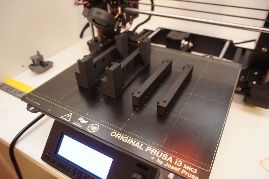
Step Two: Printing Parts
You need to print the following details and in the following quantity (to avoid confusion, the original text):
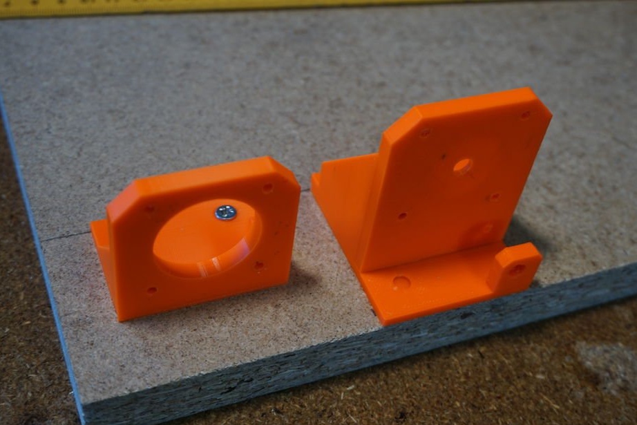
Bender
Tool head
Motor frame
Feeeder
Motor frame
Bottom frame
Wire guide
Idler gear carriage
Idler gear spacer
Feeding gear spacer
Bending plate (template)
Straightener rollers (2x)
Bed frame (2x)
Top gears frame (2x)
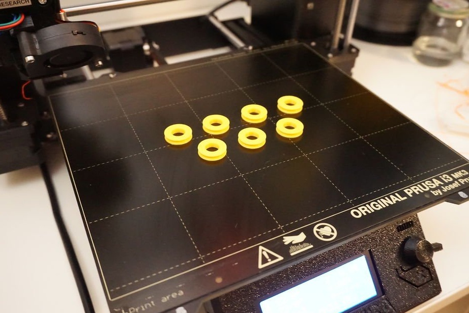
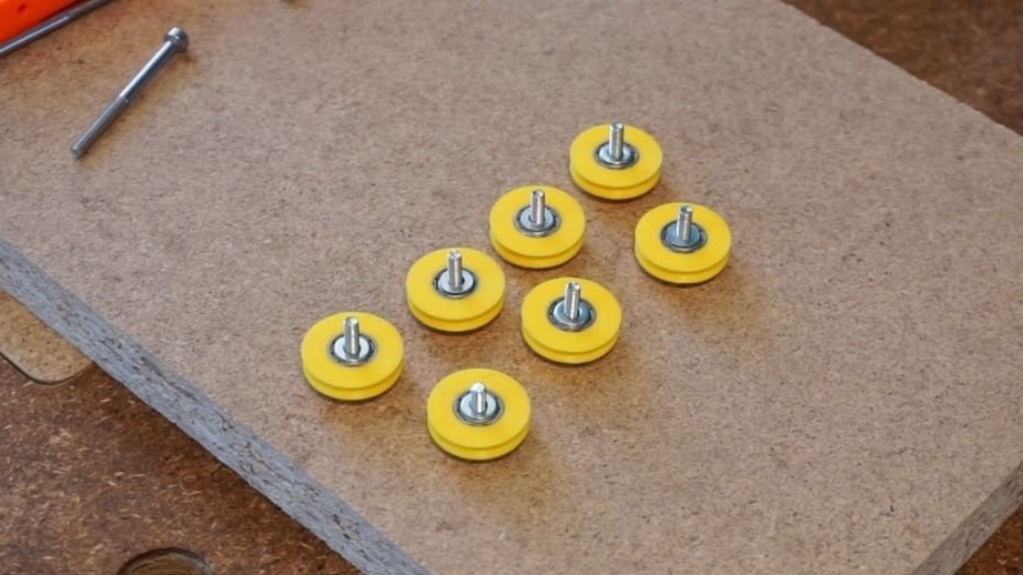
Roller (14x)
Spool holder
Layer height when printing 0.15 mm. 40% filling. Printing takes 2 days.
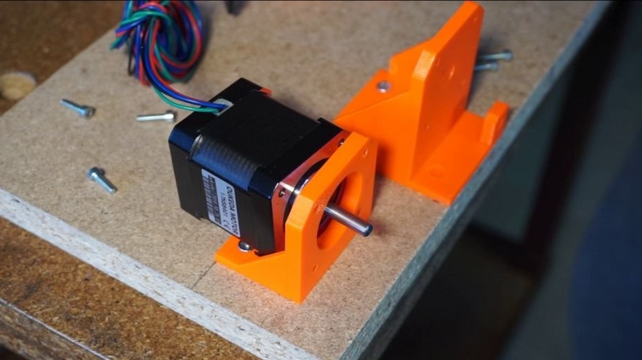
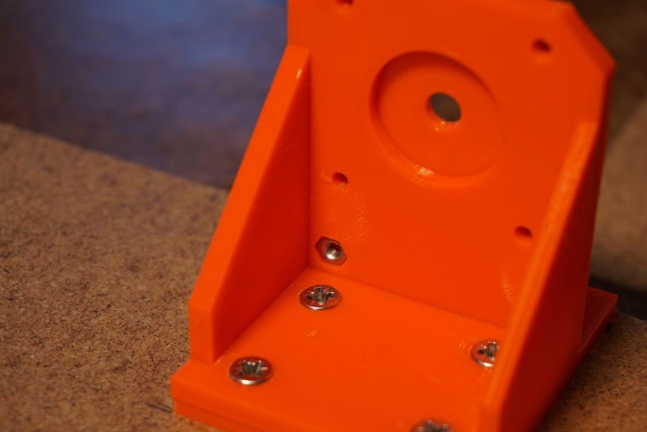
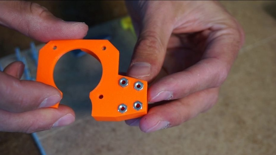
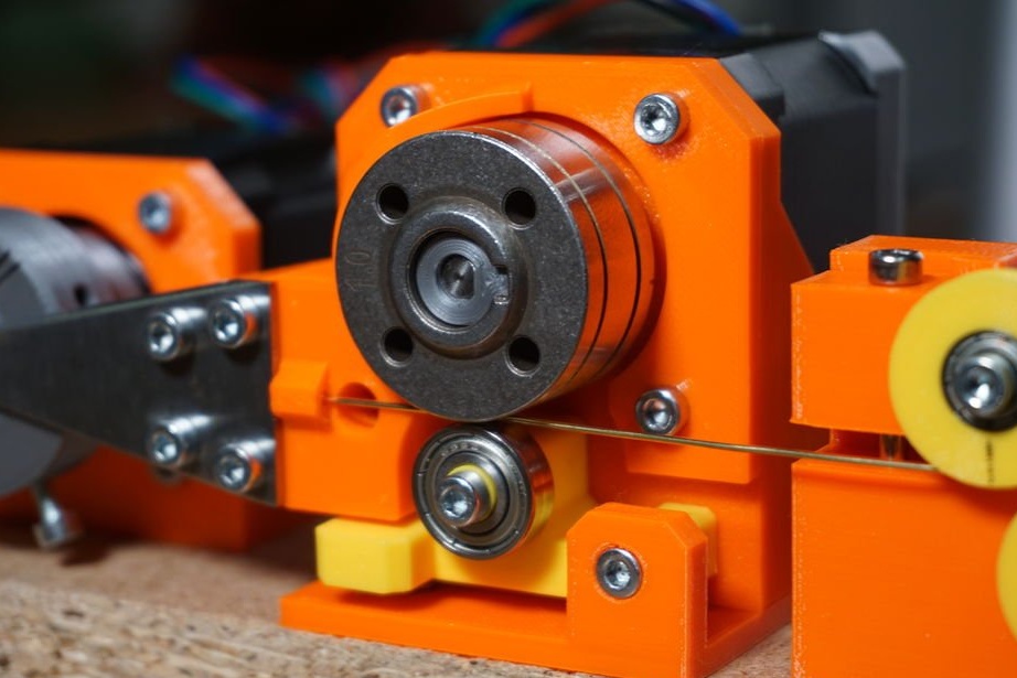
Step Three: Bending Machine
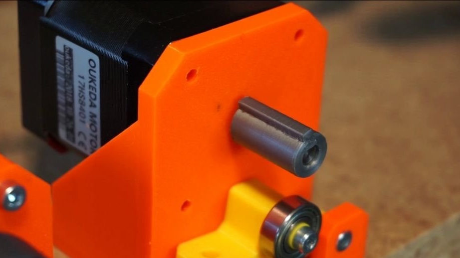
The master screws two frames to the base. It is important to install both frames as shown in the drawing.
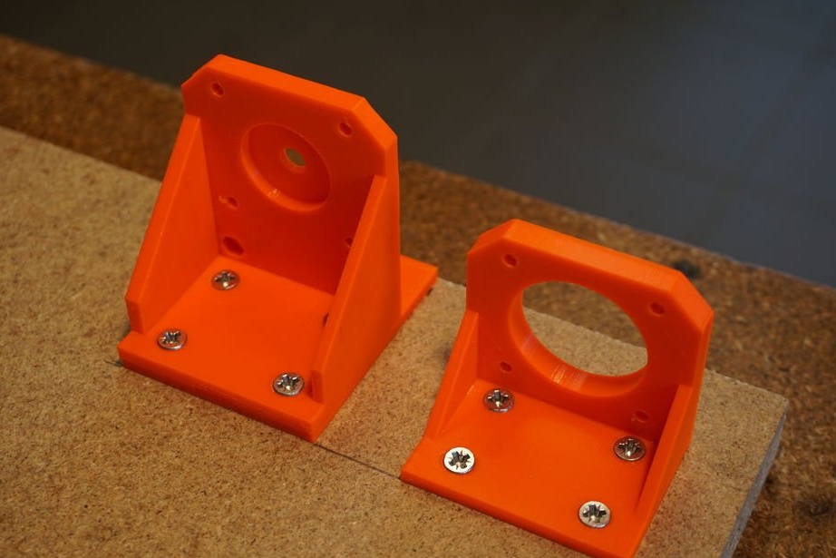
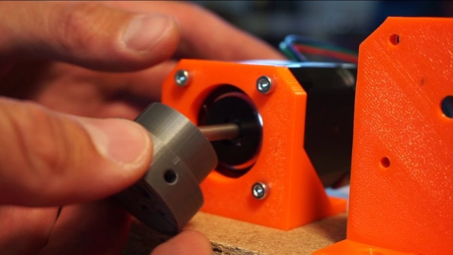
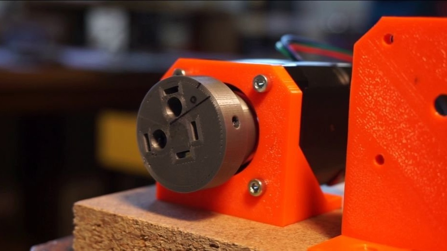
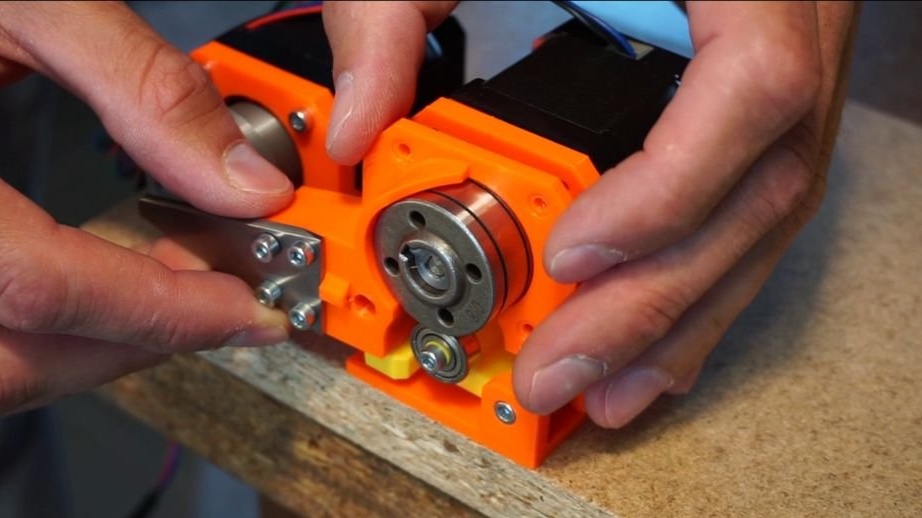
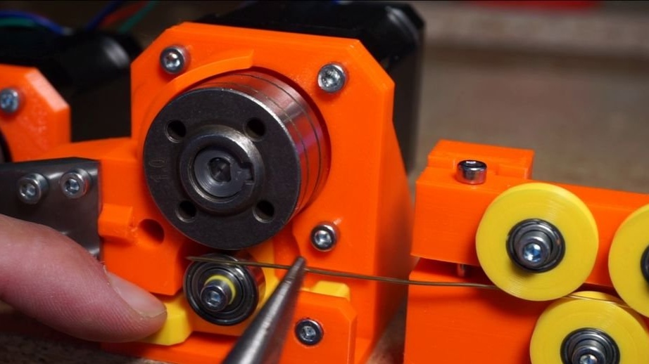
Secures the stepper motor to the frame. Secures the head to the motor shaft.
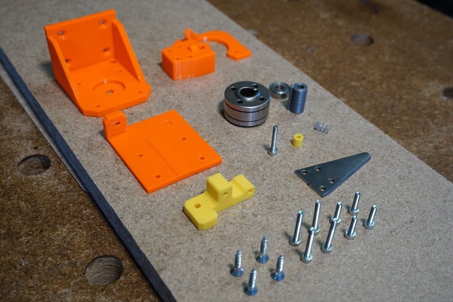
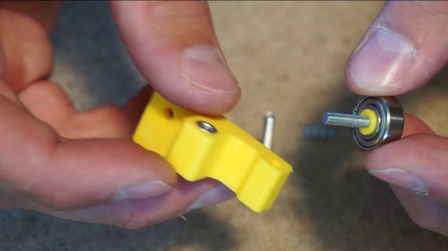
Step Four: Broach
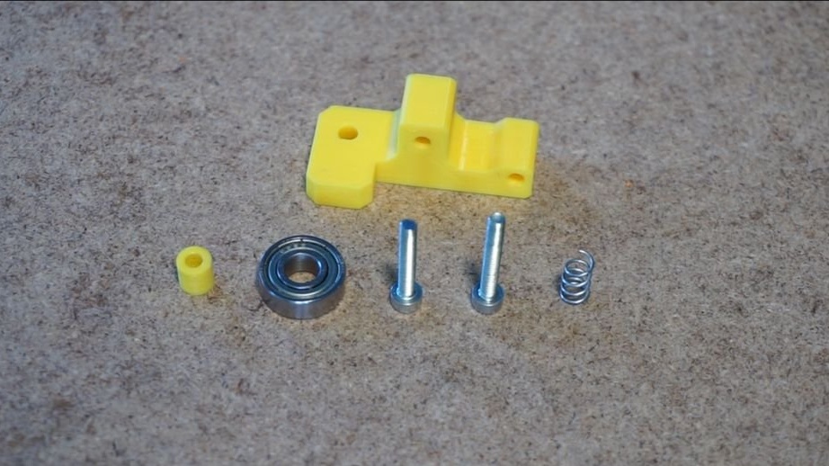
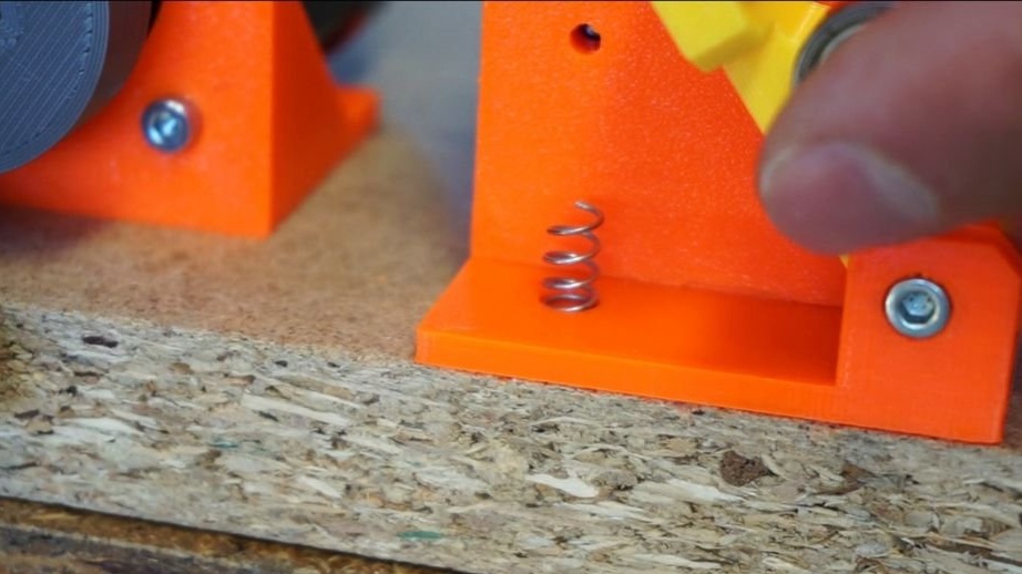
The frame is already installed, so the first step in creating a feed mechanism is to build a carriage for the intermediate gear, which will press the wire to the feed mechanism. Remove the plastic gasket inside the 6x15x4 mm bearing. Install the bearing to the M3x20 bolt. Install the M3 nut in the carriage and screw the bearing onto the bolt. Ensure that the bearing rotates freely. Insert the second M3 nut into the engine frame (engine side in the lower left corner) and screw the carriage through the small bracket using the M3x20 bolt. Do not overtighten the bolt; the carriage must move freely. Lift the carriage and insert the spring into the hole below it.
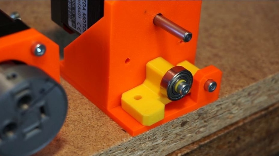
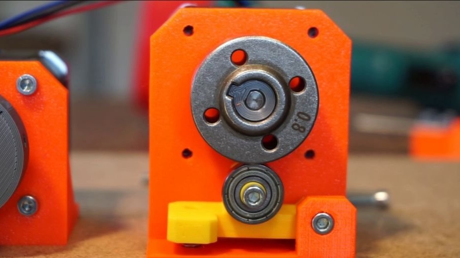
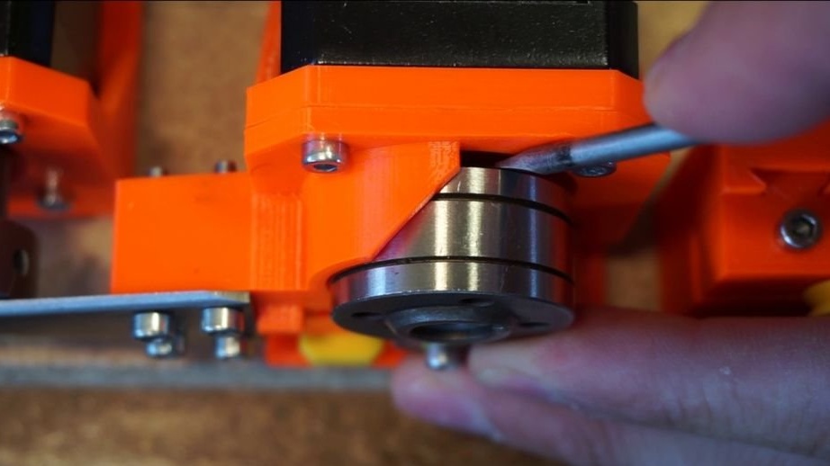
Take the second stepper motor and install it in the motor frame. Do not screw yet. Press the spacer of the feed mechanism to the motor shaft and install the feed mechanism.
The feed mechanism that the master uses is taken from a MIG welding machine. The mechanism has two recesses on the coil. One for 0.8 mm wire and one for 1 mm wire. Unlike gears (previously the master tried to feed the wire with them), this mechanism does not leave traces on the wire.
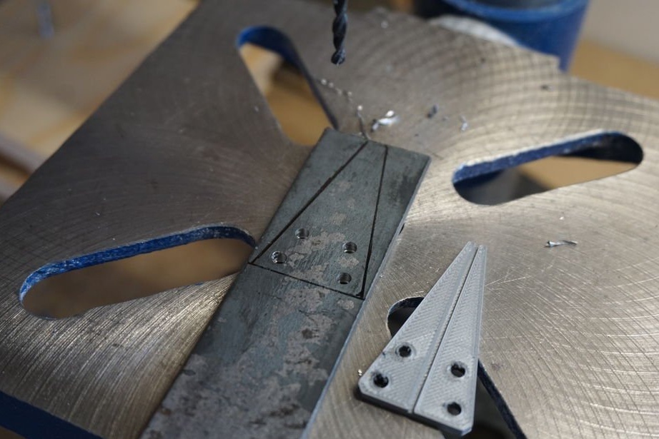
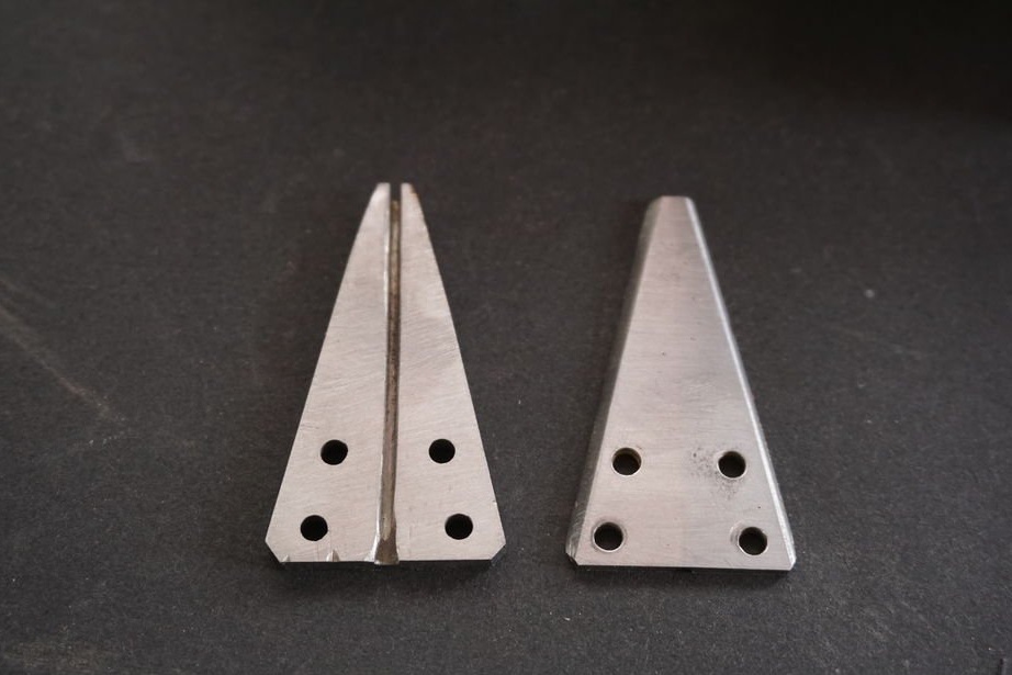
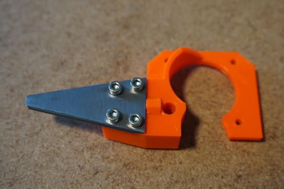
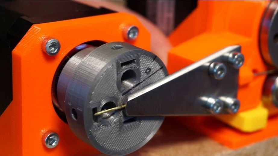
The feeder and bending device are connected by a bending plate - a 2 mm thick metal plate with a small groove on the back wall, which feeds the wire directly to the center of the bending head for perfect bending. For printing, there is a plastic bending plate that works great, but wears out quickly and requires frequent replacement. You can use it, or you can make a metal plate on it.
Next, take the plastic part of the wire guide and install the four M3 nuts in the holes on its rear side. Now screw the bending plate with the M3x20 bolts. Place the wire guide in front of the engine frame of the feed mechanism and secure it to the engine with four M3x12 bolts. Adjust the position of the bending plate. It should be exactly in the center of the bending head.
The broach is ready. If you have a straight wire, you can use the wire right now. Otherwise, you need a rectifier.
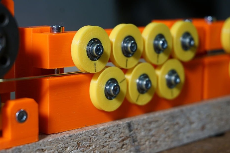
Step Five: Broach
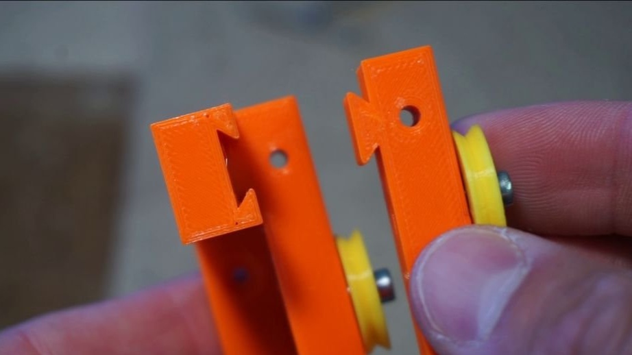
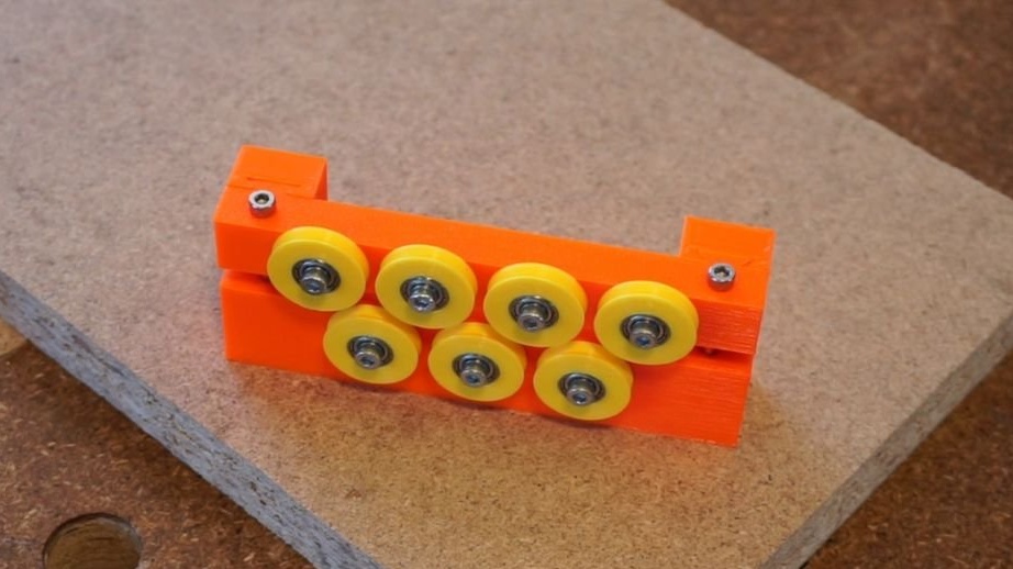
The wire is usually supplied in coil form. To bend the wire, you first need to straighten it. The rectifier consists of 7 rollers (4 on the top and 3 on the bottom), which can be pressed against each other to ensure the correct tension of the wire. It also prevents twisting of the wire during bending.
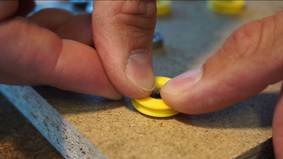
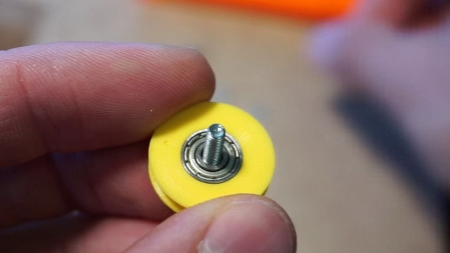
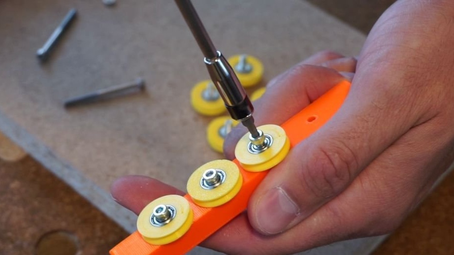
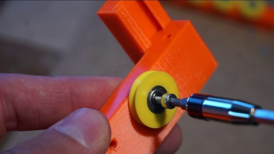
Start the assembly with the roller casters. First you need to press the bearing 3x10x4 mm into the plastic roller housing. Insert the M3x12 bolt on one side and the M3 washer on the other side of the roller. The washer will prevent friction of the wheel on the frame. Screw all the rollers to the lower and upper frame. Connect both frames. Secure the frames with two M3x40 bolts.
You can save some money on roller bearings. Print the Straightener_RollerNoBearing part instead of the Straightener_Roller. But performance will be a little worse.
For even better results, use 2 straighteners in a row.
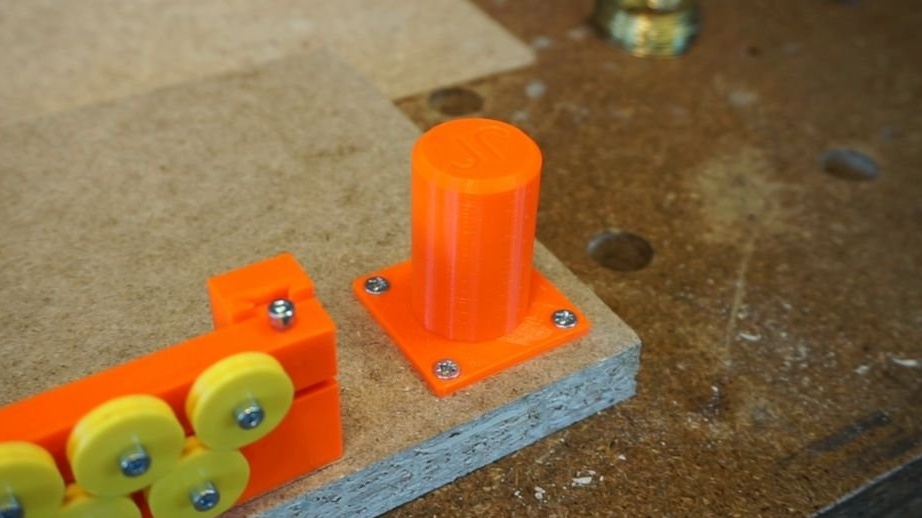
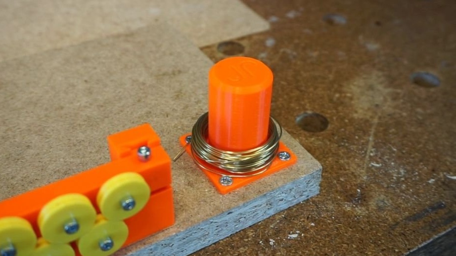
Step Six: Coil Holder
The spool holder is a simple cylinder that holds the wire and allows it to unwind from the spool. Screw it to the base with four 3x16 screws.
Step seven: connect
First, the bending wire must be fed to the machine. The master uses 0.8-1mm brass wire in the shape of a coil.
The wire goes from the coil through the rollers. Just stick the wire between the rollers. Then she goes through the broach.Adjust the position of the feed mechanism so that the gutter is flush with the surface of the wire guide. Press the lever in the intermediate gear and push the wire through the feeder to the bending plate. Release the lever and let it press against the feed mechanism. You can now scroll the feed mechanism manually to push the wire to the bending head. Carefully adjust the tension on the rollers by tightening the bolts. The rollers should not rotate freely, but the wire should move smoothly.
Secondly, electronics The controller must also be connected. The master uses the classic Arduino UNO with CNC and two A4988 stepper motor drivers. The feed motor is connected to the Z axis, and the bending head motor to the X axis. The drivers are configured for the highest possible accuracy - all 3 jumpers under the step drivers are inserted. Everything should be connected to a 12V 3A power supply.
Step Eight: Firmware
Now you can try to start the machine. Master uses GRBL together with cncjs. They are designed to work on a milling machine, but work great for any type of CNC. GRBL is the firmware you need to install in Arduino UNO. There is a good cncjs web client for setting parameters. Install GRBL on Arduino and cncjs on your computer.
After installation, you need to connect to the machine and check its operation by pressing the buttons Z +/- or X +/-.
Now you need to calibrate: 10 mm = Z10 $ 102 = 34 $ 110 = 1600 $ 111 = 600 $ 112 = 1000 $ 120 = 500 $ 121 = 350 $ 122 = 350
This is a set of values that determine how to convert the number indicated in the code into engine movement. For example, if you set the Z axis to 30, it actually means that he will push 30 mm of wire through the feeder.
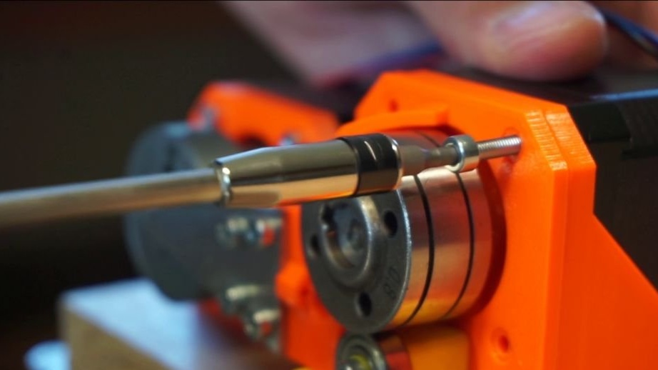
We figured out the calibration, now you need to set the bending head to the zero position.
The movement of the bending head is determined by the well-known fixed position of the bending head. In this case, this is the position in which the bending pin on the head is facing left. See the photo.
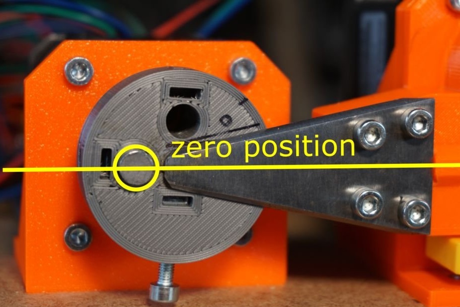
It is advisable to note this zero position on the head in order to be able to return it to the same position. There is no need for the feed mechanism to determine the zero position, because it always moves relative to the current position.
Now let's look at a Gcode example. It looks like this:
G91
G1 Z1
G90
G1 X2
G1 X-6
And here is what each value is written for:
G91 - use relative coordinates (required before any movement along the Z axis)
G1 Z1 - feed 1 mm wire
G90 - use absolute coordinates (required before any movement along the X axis)
G1 X2 - turn the bending head to position 2 (this number does not have units)
G1 X-6 - turn the bending head to position -6
If you repeat the steps 100 times, you will get a spring bend code. More source files can be found below.
hex-inner.gcode
hex-outer.gcode
spring.gcode
The machine is ready. But the master will still work on improving it.
The whole process of manufacturing such a machine can be seen in the video.