

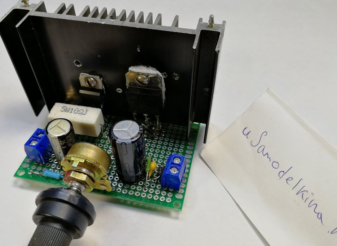
In this article I will talk about another linear voltage regulator, which I assembled relatively recently. It is built on the popular LM317 chip and a bipolar PNP transistor. The finished module is as follows:
Related video:
In the past article I talked about a similar linear voltage regulator on TL431 and NPN transistors.
This circuit, in contrast to the aforementioned, contains slightly fewer parts, and is able to withstand higher currents, thanks to a more powerful transistor.
Main characteristics:
• Input voltage up to 30V (in my version, because the capacitor at the input to 35V)
• Output voltage 3-25V (depending on the current, the higher the current, the lower the maximum output voltage)
• Current up to 9A (with a TIP36C transistor with an input voltage of 18V and an output of 12V, but generally depends on the selected transistor and power dissipation)
• Stabilization of the output voltage when changing the input
• Stabilization of the output voltage when the load current changes
• Lack of protection against short circuit
• Lack of current protection
The module is assembled as follows:
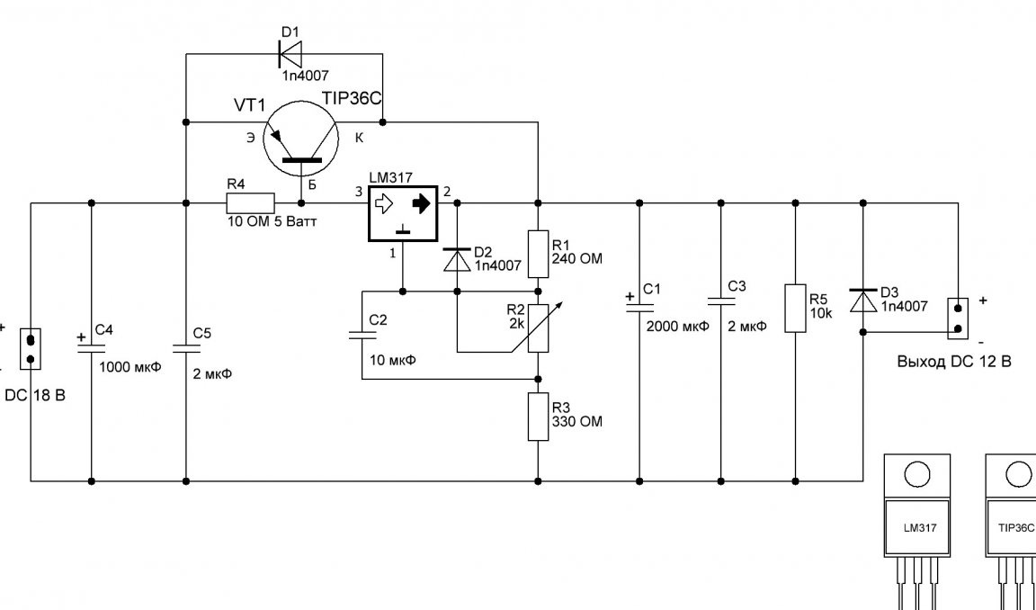
Explanations according to the scheme:
The LM317 microcircuit purchased on AliExpress (most likely not the original one) has 3 outputs. The findings are indicated in the diagram and the picture in the lower right corner.
The chip controls a powerful bipolar PNP transistor VT1. I used TIP36C for this purpose. The main characteristics of the transistor: voltage - 100V, collector current - 25A (in fact, 8-9A, because the transistor is not original and was bought by Ali Express), a static current transfer coefficient of 10.
It is very important to monitor the power dissipated by the transistor so that it does not exceed 50-55 watts (for a transistor in a TO-247 package or similar in size, and for transistors in a TO-220 case - no more than 25-30 Watts). You can calculate by the formula:
P = (U output -U input) * I collector
For example, the input voltage is 18 V, we set the output voltage to 12 V, the current we have is 9 A:
P = (18V-12V) * 9A = 54 Watts
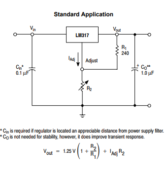
Resistors R1, R2, R3 set the voltage that our circuit will stabilize. Resistor R1 is taken as standard at 240 ohms (any power). Resistor R2 is variable, it is better to take in the region of 2-3k ohms. Initially, I set it to 4.7k Ohm, as a result, somewhere in the middle of the knob's rotation range, the voltage reaches its maximum value and does not change further.I soldered a 3.9k Ohm resistor parallel to the potentiometer, the adjustment became smoother and the entire range of knob rotation began to be used. Resistor R3 is optional, serves to slightly move the lower and upper boundaries of the adjustment range towards the increase. General rule: the greater the total resistance of resistors R2 and R3, the higher the output voltage. This is confirmed by the formula from Datashita:
Resistor R4 is used to slightly limit the current to the input of the LM317 chip. Resistance 10 Ohm. LM317 as much as possible can pass through itself about 1A (up to 1.5A, if the original). At first glance, the power of the resistor R4 should be:
P = I ^ 2 * R = 1 * 1 * 10 = 10 Watts
But since the current also passes through the base of the transistor VT1, bypassing the resistor, you can take the resistor R4 and 5 watts.
The above components form the core of the circuit; everything else is additional elements to improve stability and provide some protections.
Capacitor C2 (ceramic 1-10 microfarads) - is soldered in parallel with a variable resistor and improves stability of regulation. To protect the LM317 microcircuit when the capacitor C2 is discharged, a D2 diode is placed. They, together with the D1 diode, protect the microcircuit and the transistor from reverse current. Diode D3 serves to protect the circuit from EMF self-induction when powered by electric motors. Capacitors C4 (electrolytic 35V 470-1000 uF) and C5 (ceramic 1-10 uF) form an input filter, and capacitors C1 (electrolytic 35V 1000-3300 uF) and C3 (ceramic 1-10 uF) form an output filter. Resistor R5 at 10k Ohm (any power) creates a small load for the stability of the circuit at idle and helps to discharge capacitors faster in case of power failure.
Build process:
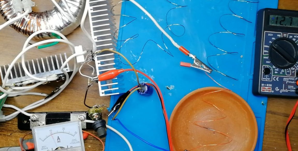
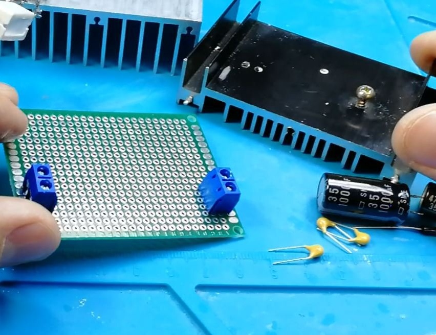
At first, everything was assembled by hinged installation and tested.
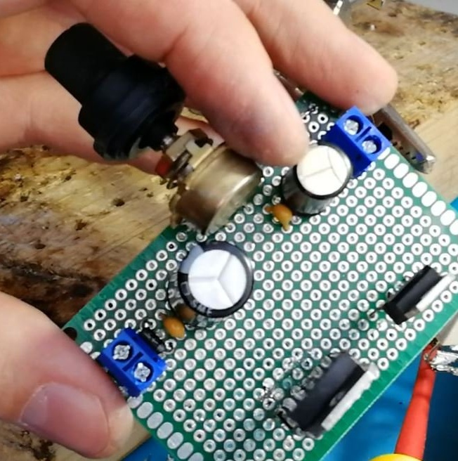
Then I soldered the circuit on the breadboard in the form of a module.
Added a small radiator.
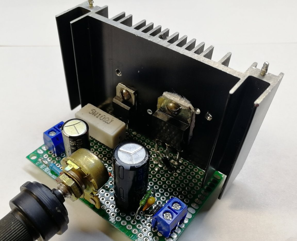
With such a radiator, the circuit can work for a long time only at low currents. In order for the circuit to work for a long time at full power, you need a more massive radiator.
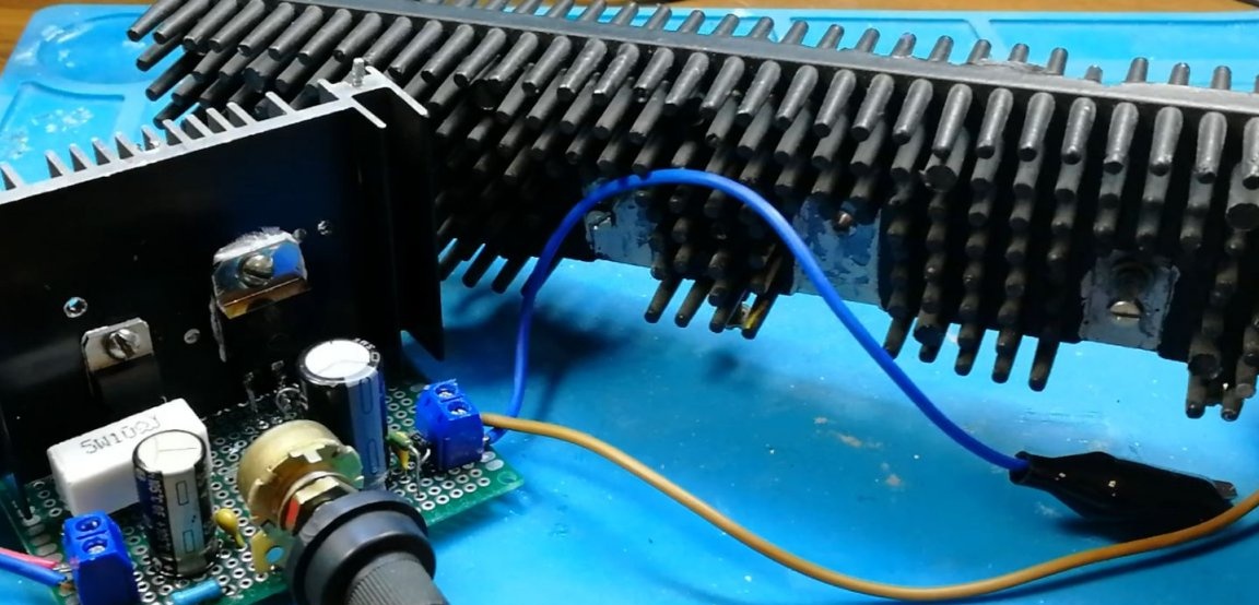
LM317 and transistor can be mounted on a radiator without insulating gaskets, as According to the scheme, these conclusions (LM317 output and transistor collector) are connected.
I tested the finished module and checked the characteristics.
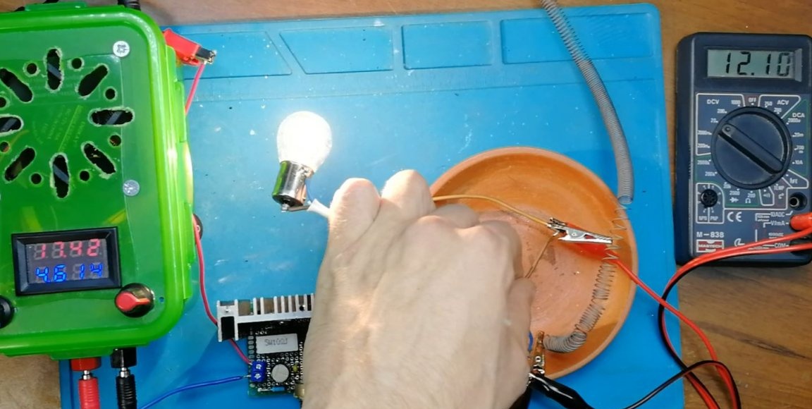
In general, I liked the circuit: quite simple and you can get a decent current. What is missing is protection against short-circuit and current. Well, it’s over. The efficiency is not high and it gives off a lot of heat. But this is a feature of all such linear circuits, which personally does not really bother me.
Thank you all for your attention! I hope the article was useful to you.