

Greetings the inhabitants of our site!
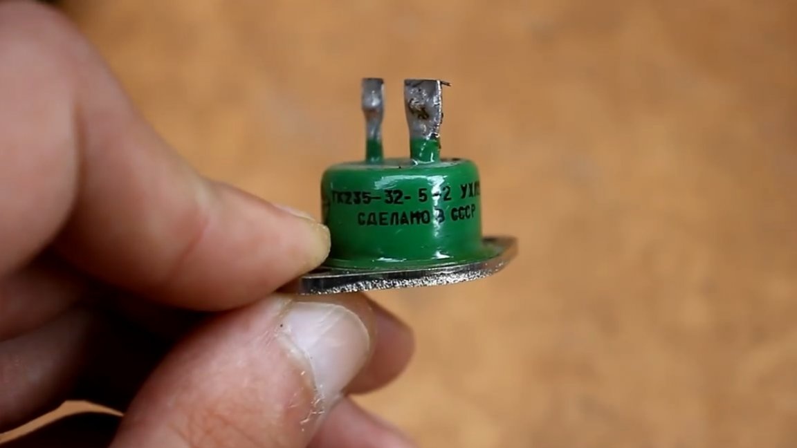
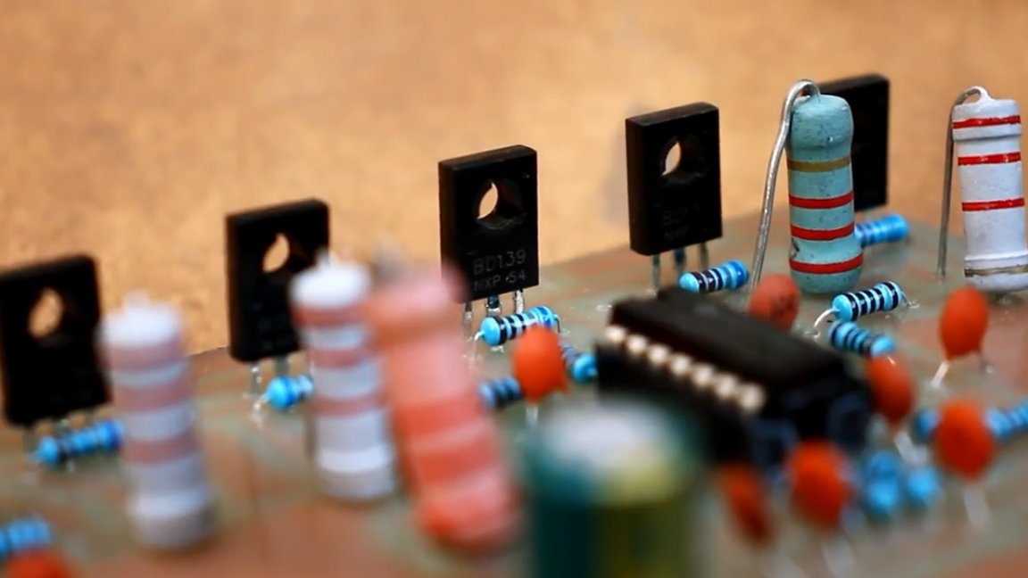
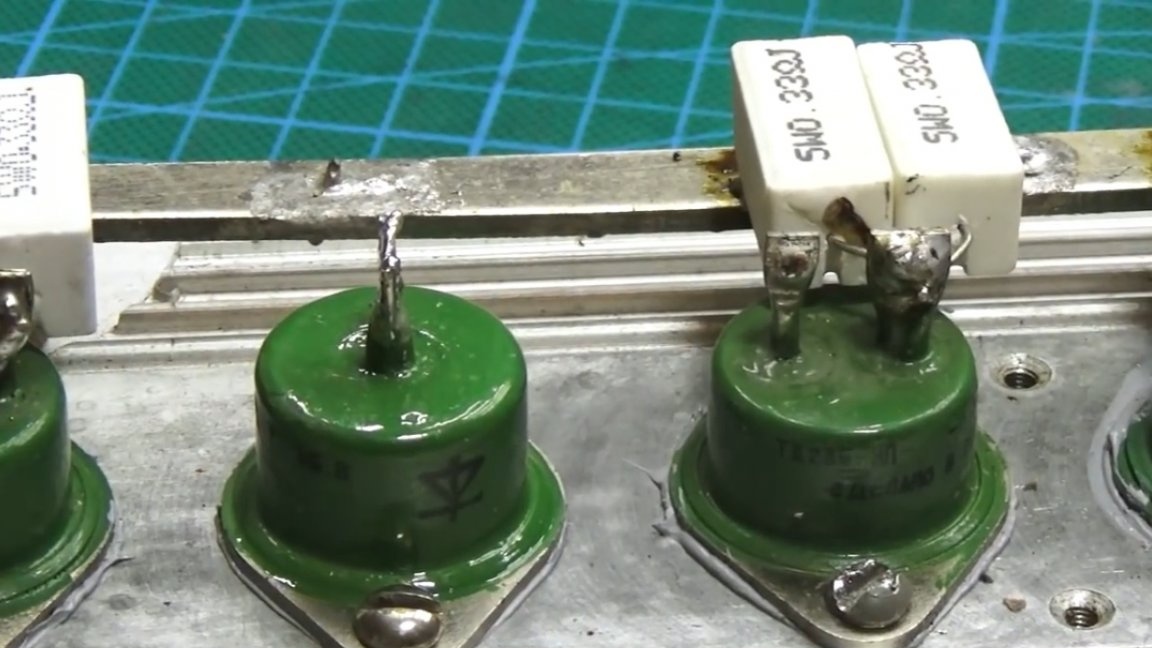
Here is a fairly powerful TK235-32 power bipolar transistor with a collector current of as much as 32 amperes and DCH135-80 power diodes of 80A.
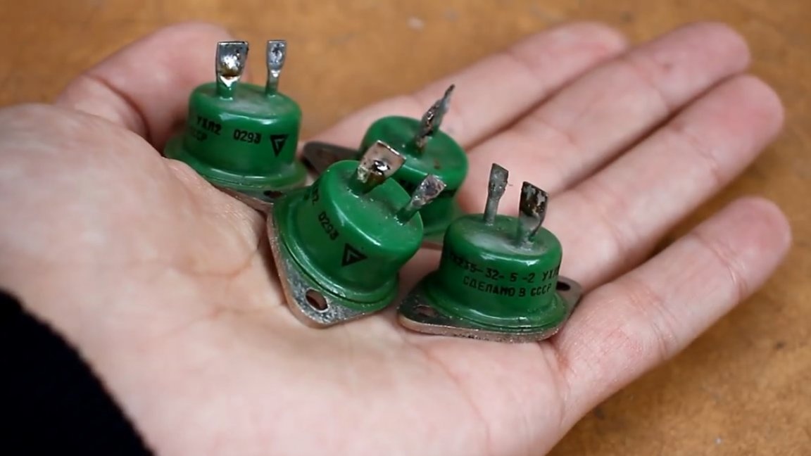
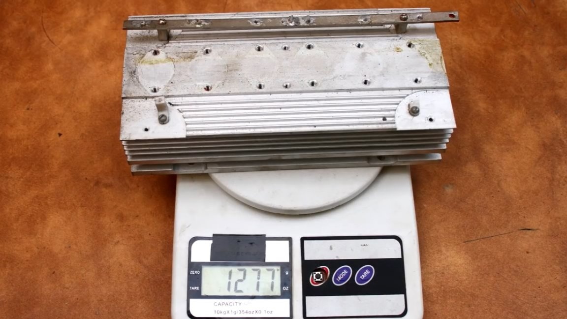
The author of the YouTube channel “AKA KASYAN” acquired these monsters at a local flea market, they also included the appropriate radiators.
So, what can I do using such components? The first thing that comes to mind is a laboratory linear power supply unit of tremendous power. But the author already has one in the workshop, but electronic high power load - the device is much more in demand at the moment (well, at least for the author of this homemade product), so it was decided to make do it yourself electronic load using the parts at hand.
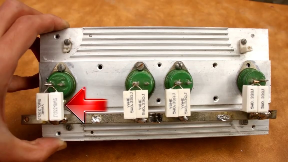
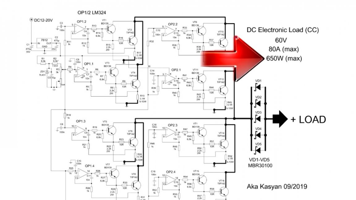
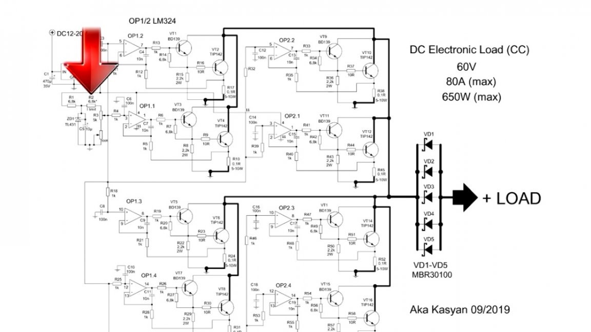
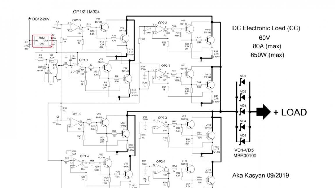
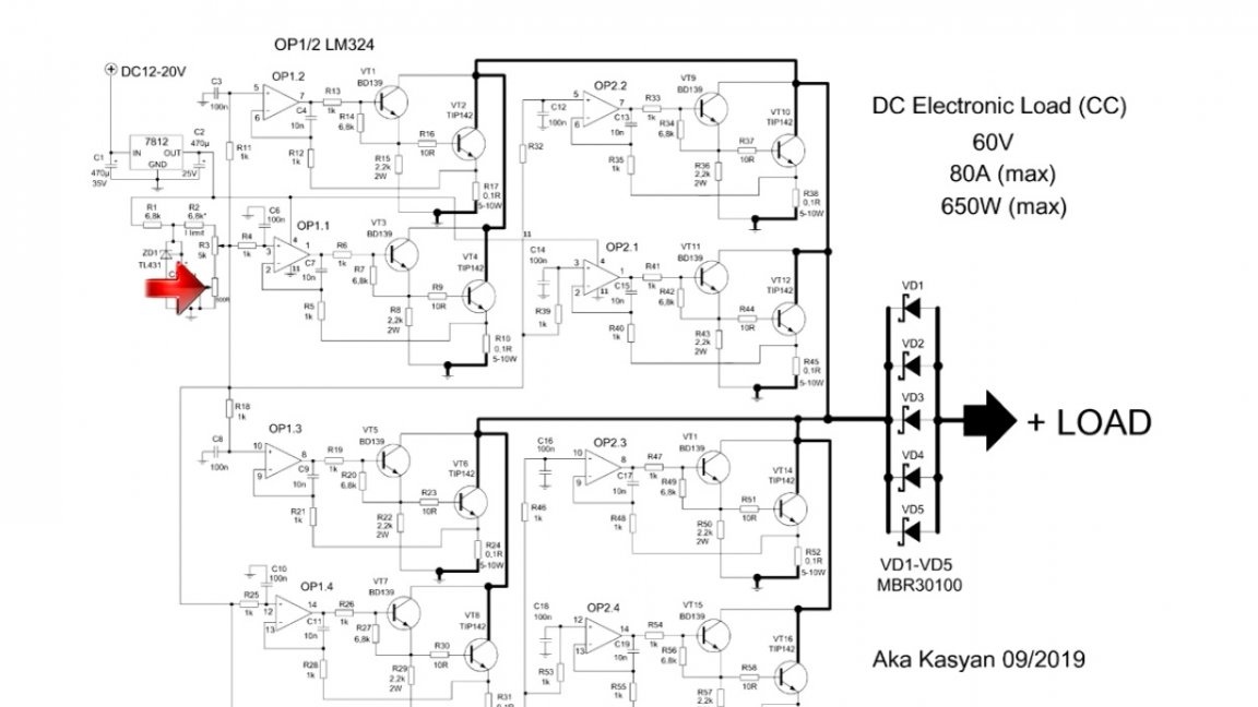
First, let's go over main characteristics the aforementioned device. The current adjustment range is literally from 0 to 80A, briefly up to 100A, in theory it is possible to remove up to 200A, provided that the current sensors (marked in the image below) are replaced with lower-resistance ones.
The maximum input voltage up to 60V, and more can be, it all depends on the voltage of the transistors.
Also, the electronic load is protected against reverse polarity. The maximum power dissipation is about 1500-1600W. Such a device can load almost any power source, even welding inverters can do it, but it is important not to exceed the maximum power, and here, as mentioned above, is 1600W. It is worth noting that all 1600W in this case will go to heating, so this is a fairly serious heater.
I think you agree that the above characteristics are really impressive for linear loads. Current loads with similar parameters cost a lot, of course, our version will be without much bells and whistles.
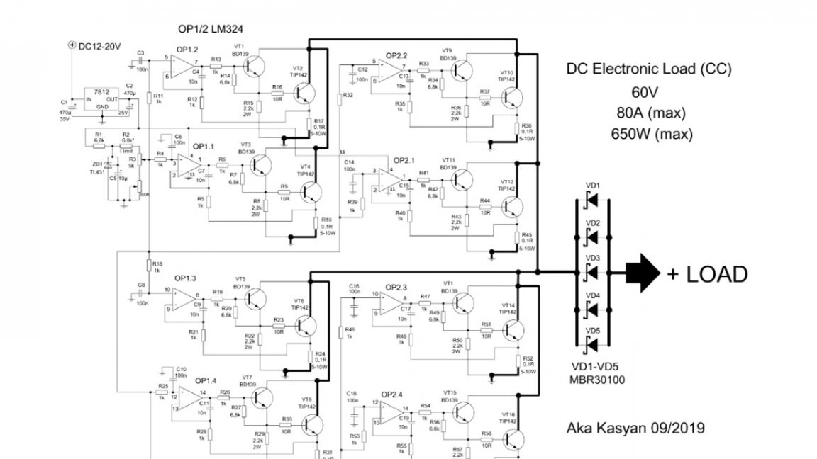
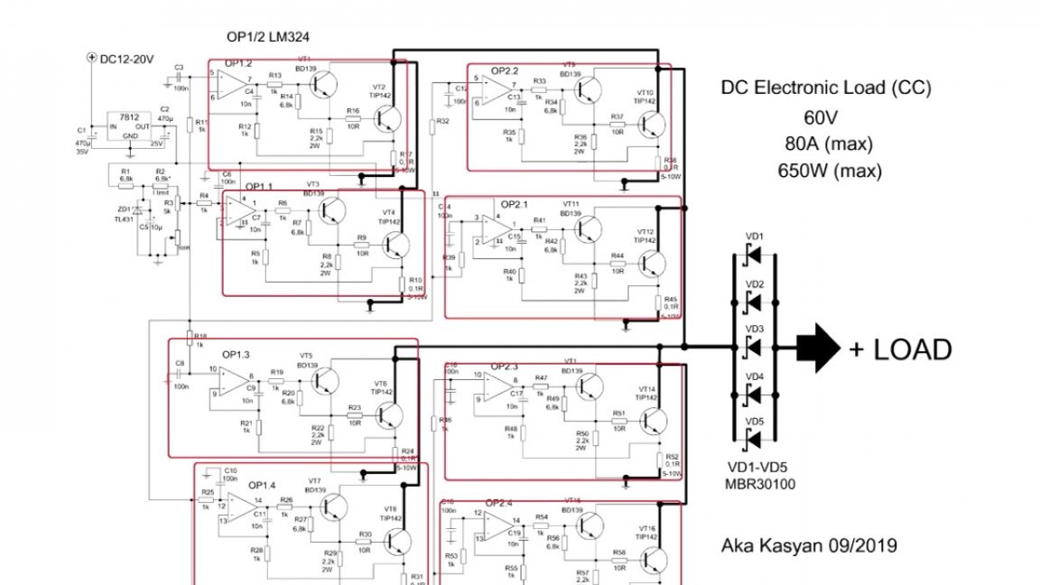
Attention! It is worth noting immediately a few points in order to avoid additional questions. At first, The circuit turned out to be quite large and most likely some small details will not be visible. You will find a good quality scheme in project archive. Also, the link to download the archive is in the description under the original video of the author.
Secondly, the values of some elements of the circuit may differ from those that are installed on the board, but the device will work in both cases.
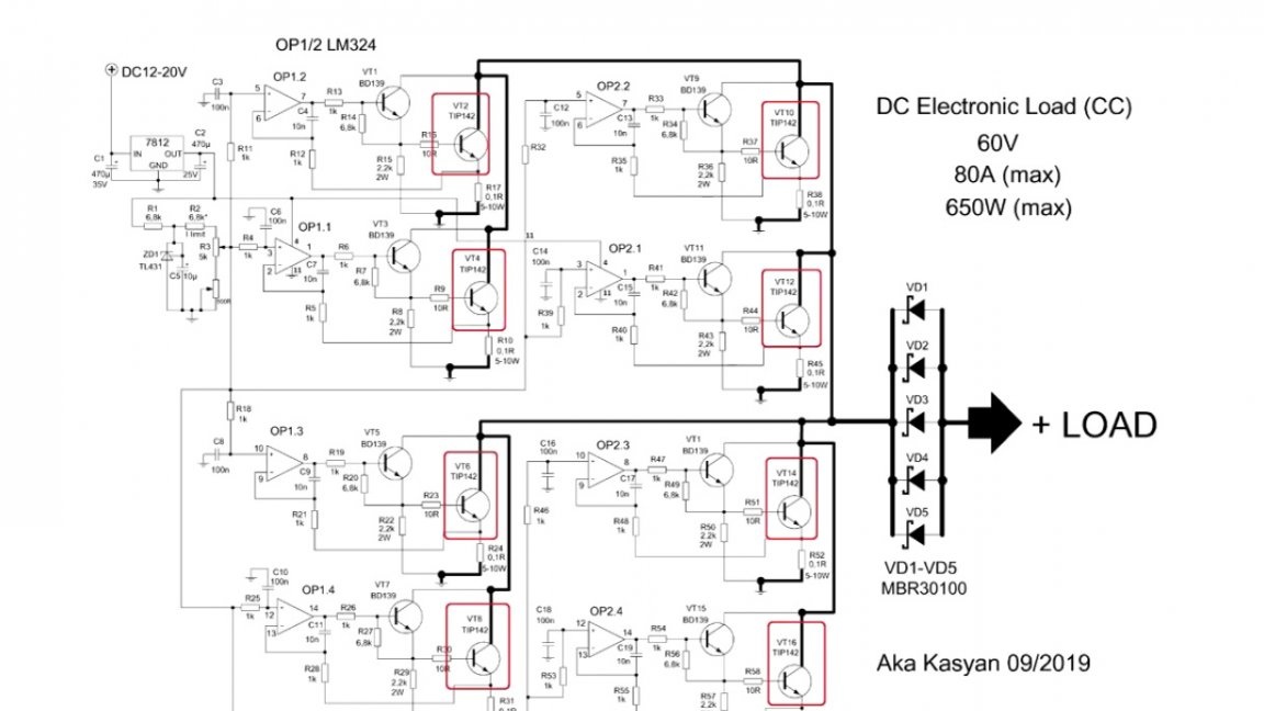
Thirdly, the most preferred ones were used in the circuit, these are composite keys that are easy to control and the driver will hardly heat up at the same time, but the total load power with the keys indicated on the circuit will be less than in this case, since the transistors are used much more powerful here.
Fourth. There are no seats on the printed circuit board for power transistors, and they are also absent for current sensors.
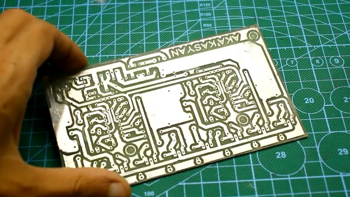
You should also pay attention to the inscriptions B (VT1), B (VT2), etc., these points are connected to the bases of the corresponding power transistors.
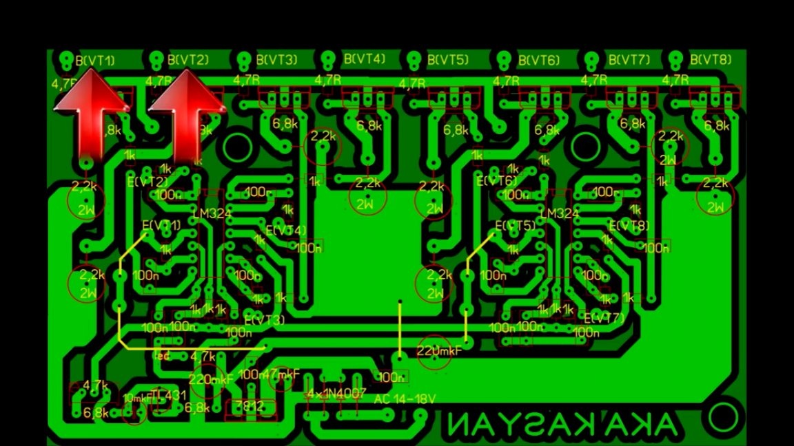
The same applies to the markings E (VT1), E (VT2) and so on, they are connected to the emitters of the corresponding transistors.
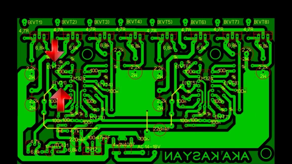
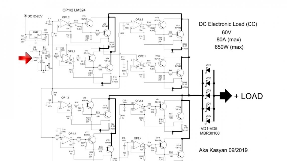
And finally, the last, fifth point. The resistor marked in the image below sets the limits of the output current.
The lower the value of this resistance, the greater the current. The specified resistor must be selected.
The author conducted numerous experiments with the resulting device to find out what power a transistor can dissipate in such a case, the maximum collector current, and how much the control driver will be loaded at different current values on the power transistor.
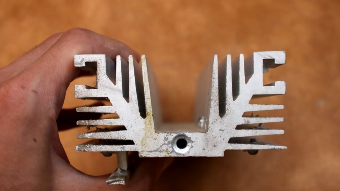
The tests were successful, not a single transistor was injured. Empirically, it became clear that the transistors declared by the manufacturer 32A are holding. The case is able to dissipate 150W, and with a fan, all 200W.
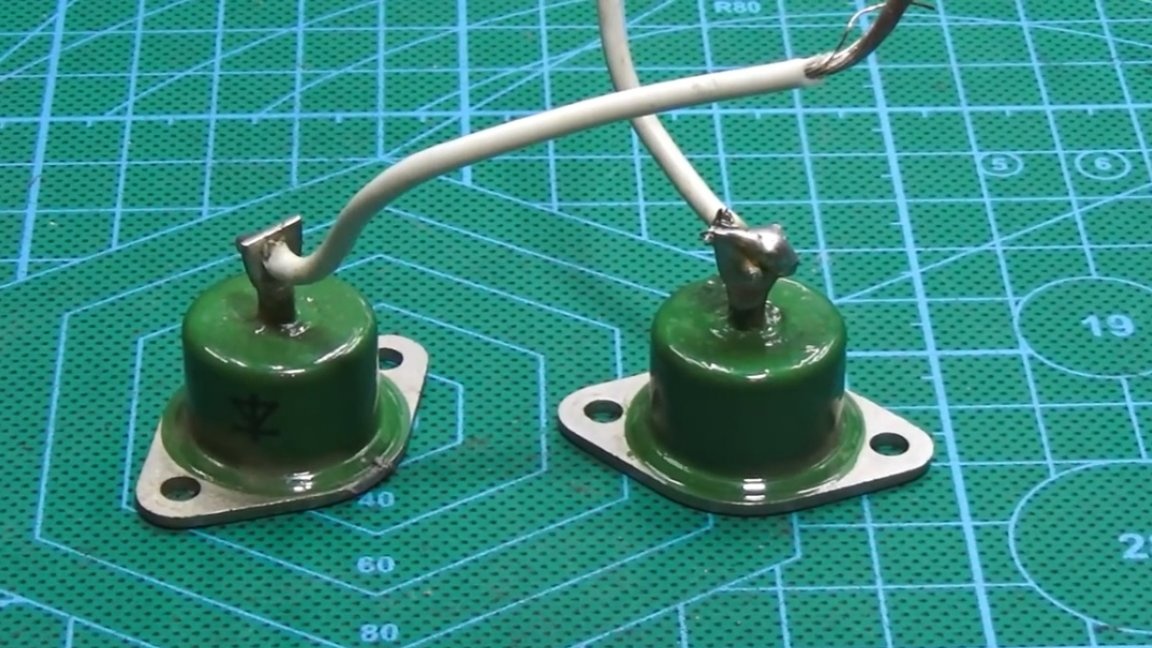
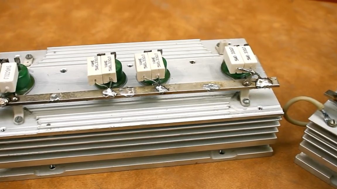
You must agree that the value of 200W from each transistor is very good. And that on each radiator, the author screwed, using thermal grease, 4 keys. There are 2 such radiators in this case.
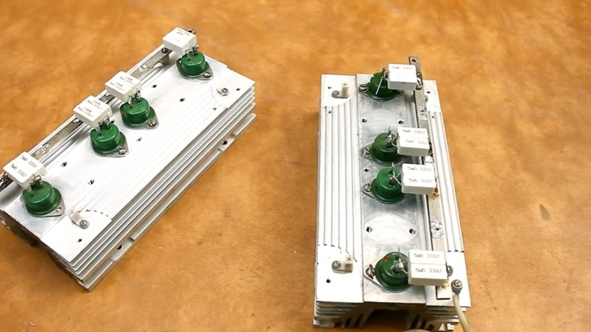
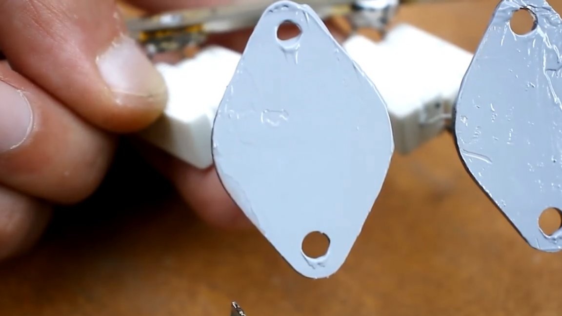
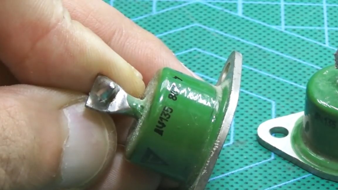
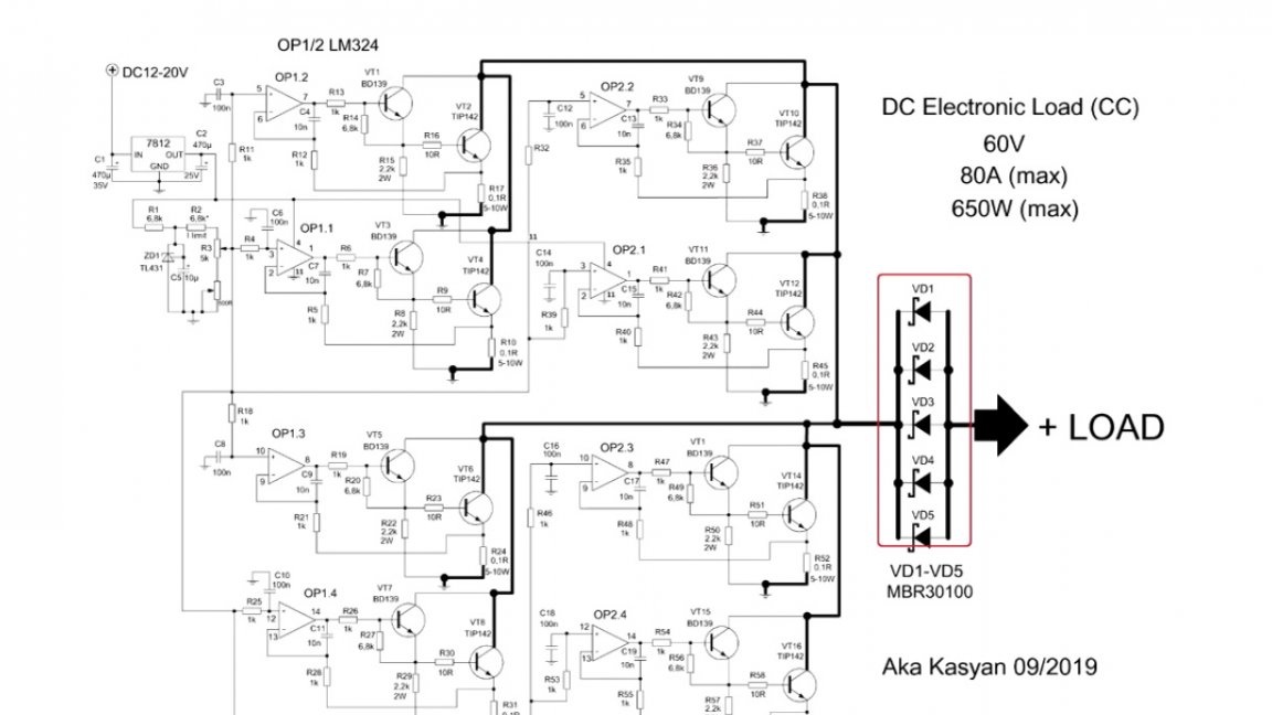
Further, in exactly the same way, one 80-amp diode was screwed onto each radiator. About their appointment later, and now let's move on to the electronic load scheme.

In fact, this is an ordinary current stabilizer on an operational amplifier. Each channel of the operational amplifier controls its own cascade, and we have 8 such cascades.
All cascades in fact are connected in parallel, but the operation of one does not depend on the other. In the emitter circuit of each transistor, a current sensor is connected in the form of 2 parallel-connected low-resistance 5W resistors. The resistance value of an individual resistor is from 0.1 to 0.22 ohms.
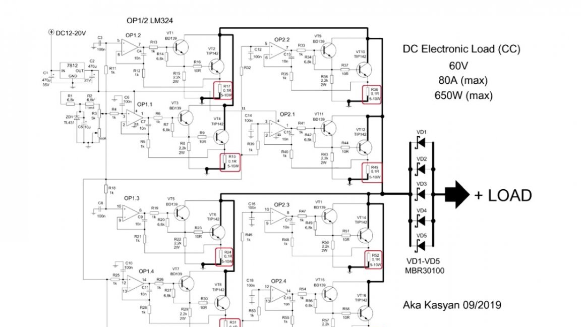
The operational amplifier monitors the voltage drop across this resistor and compares it with the reference one. Further, depending on the difference, it increases or decreases the output voltage, which in turn leads to the opening or closing of the driver transistor, and, therefore, the same thing happens with the power transistor.
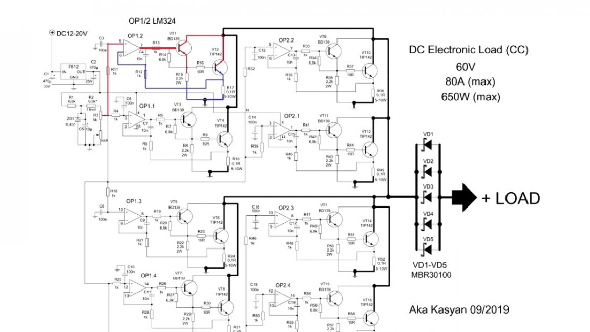
It is worth noting that the above circuit operates in a linear mode, so the transistors in the process are partially open or partially closed, it depends on the output voltage of the operational amplifier.
The more the power transistor is open, the greater the current in the circuit and vice versa. As mentioned above, all power is generated in the form of heat on power transistors and current sensors, so if you want to repeat this project, first of all take care of good cooling of these components of the circuit. The author used fairly good aluminum radiators in the form of a bar.
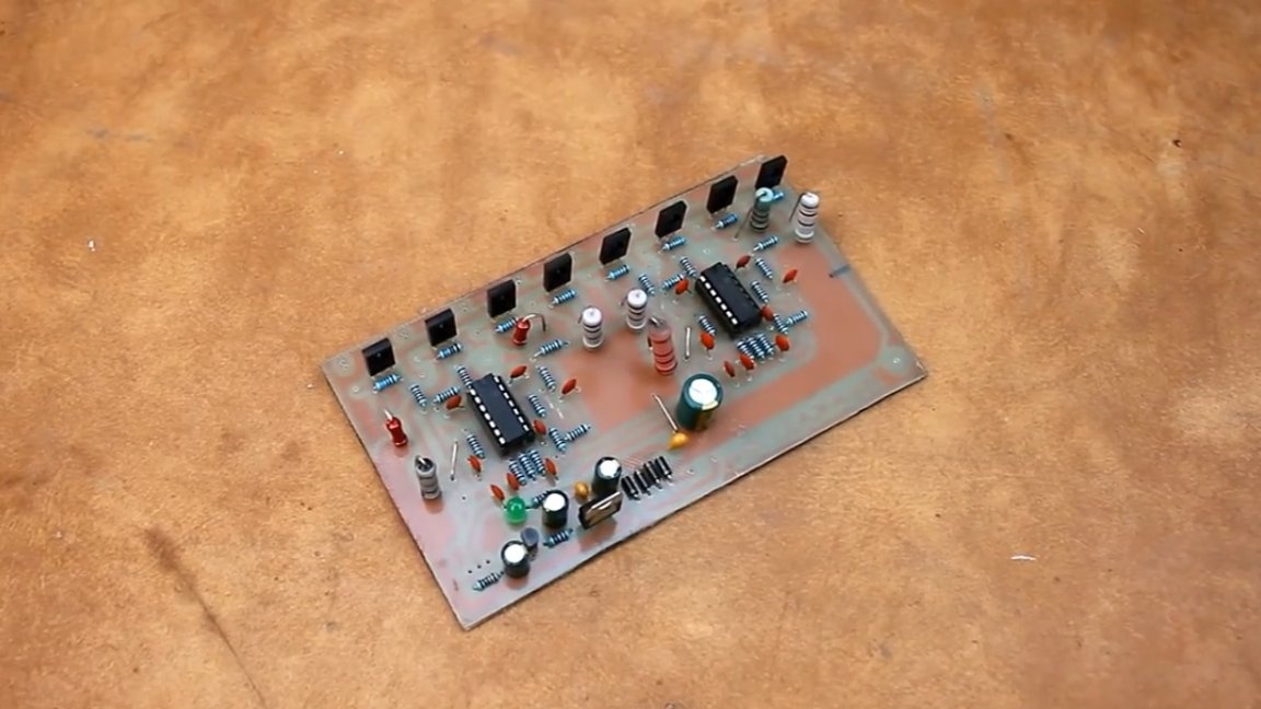
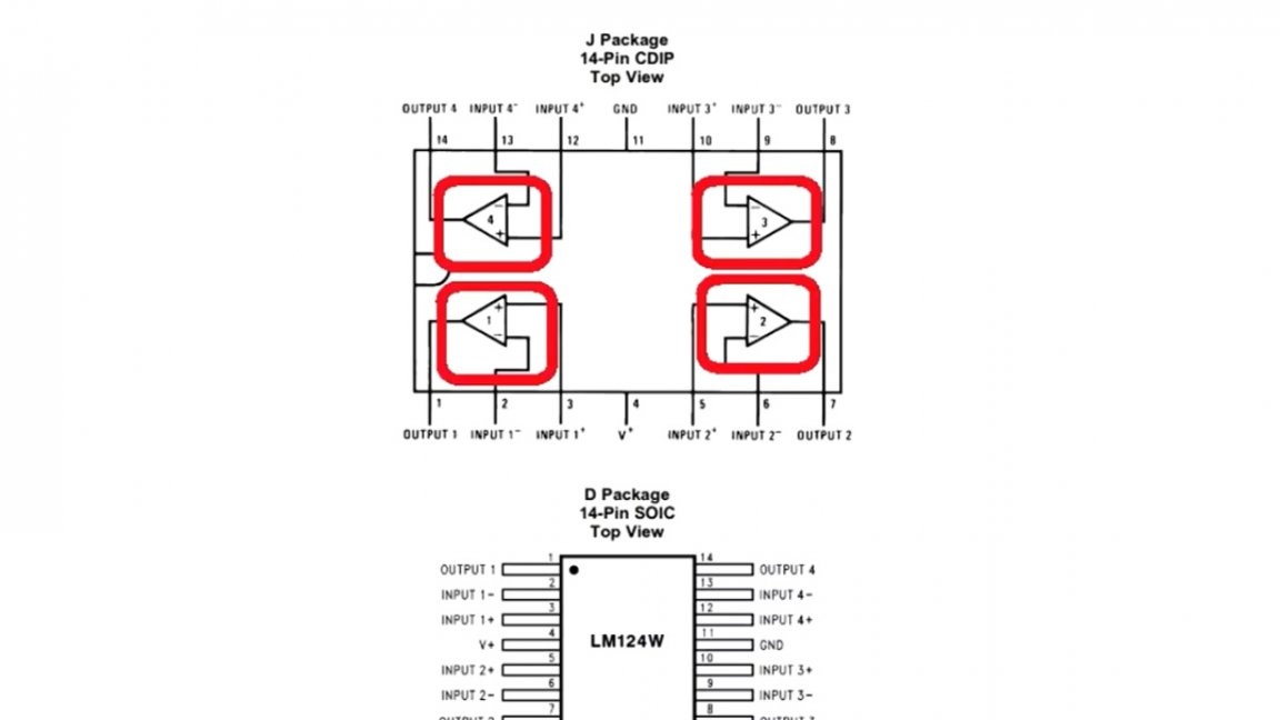
Now let's go directly to the board itself. It turned out pretty good. Since we have 8 stages and the number of operational amplifiers should be appropriate, therefore, 2 pieces were used.
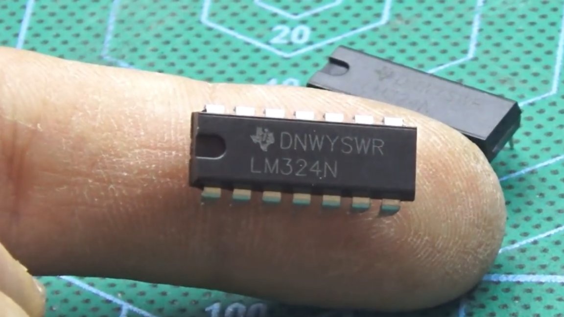
A single chip consists of 4 independent opamps, exactly what you need.
The considered circuit is powered by a linear stabilizer at 12V. The consumption of the circuit is negligible, so the 7812 stabilizer does not need a radiator.
As the cheapest available and fairly accurate reference source - the good old tl431.
Current adjustment is carried out by rotating a variable resistor:
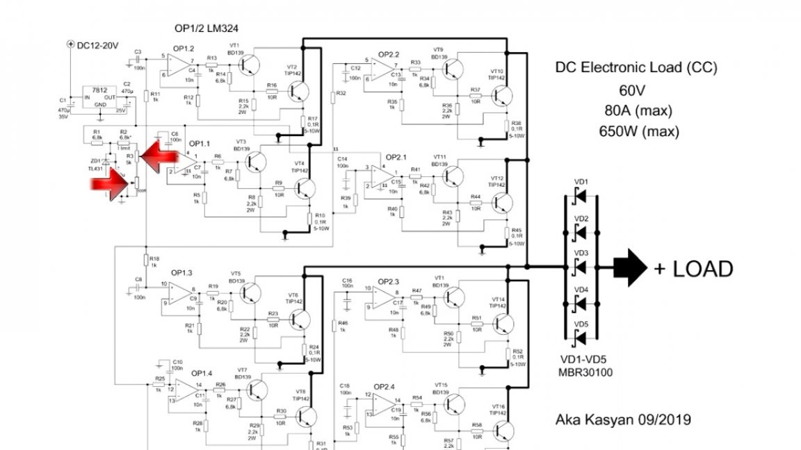
This resistor in fact changes the reference voltage.And since the load power is not small, another variable resistor of lower resistance was added.
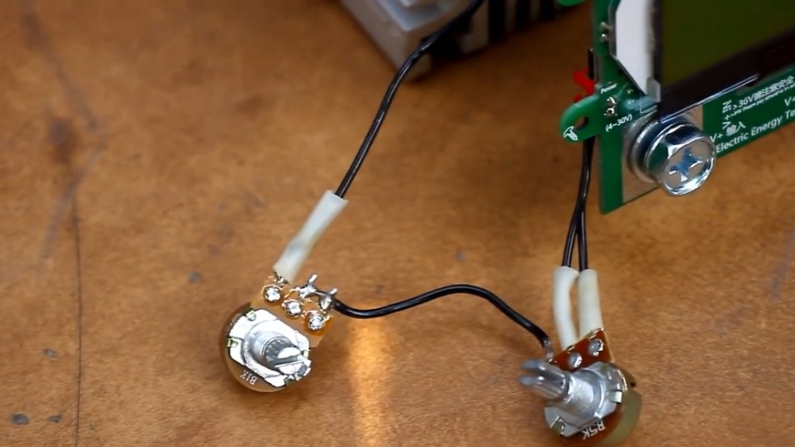
The first variable is used for coarse adjustment, the second, respectively, for a smoother. The control board needs a low power source. For example, it can be powered by batteries or rechargeable batteries. This solution will make the load completely autonomous.
Power diodes, which were mentioned at the beginning of the article, are installed at the input of the load. They are protected against polarity reversal. The reverse voltage and current of the diode should be selected with a double margin. In the future, the author plans to change the protection to another, most likely with field-effect transistors.
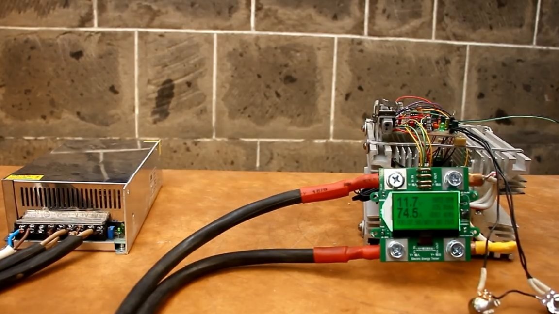
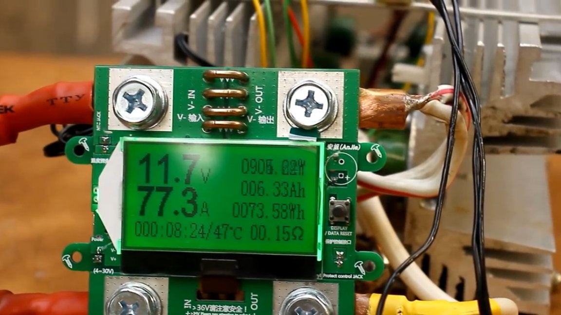
Also in this design, a multifunctional digital indicator on 300V, 100A is used.

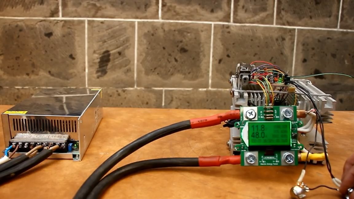
Now is the time for power testing. We will load this power source:


This is a 12V 83A switching power supply. The current is regulated quite smoothly. The power that the load is currently dissipating is about 900W.
So another monster was born into the world, it’s quite difficult to come up with a different name for this beast, horse radiators and power keys, brutal power, which is still needed for complete happiness. That's all for today. Thank you for attention. See you soon!
Author's video: