
In this article, we will consider the process of self-production of an adjustable power supply, but not with two degrees of reduction, but with one. The author of this homemade product is Roman (YouTube channel "Open Frime TV").
Almost all laboratory power supplies are as follows:
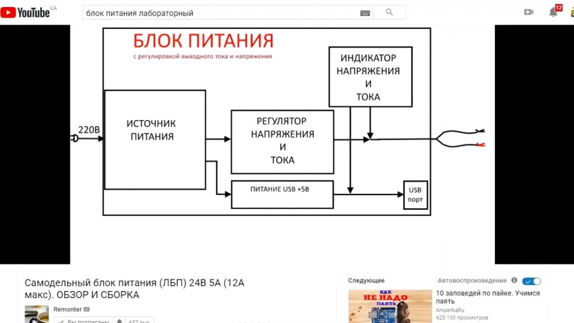
Those. First, a simple power supply unit is installed, which lowers the mains voltage to a certain level, and already after it a dc-dc converter is installed, which already performs direct adjustment of current and voltage. But why not make the adjustment directly on the high side? This solution will reduce the size of the device and significantly increase efficiency. But this is not so simple. In the process of constructing this homemade product, the author encountered many problems. And looking ahead, it is worth noting that we managed to overcome almost all the problems that arose, there was only one, albeit insignificant, but still a problem. However, first things first.
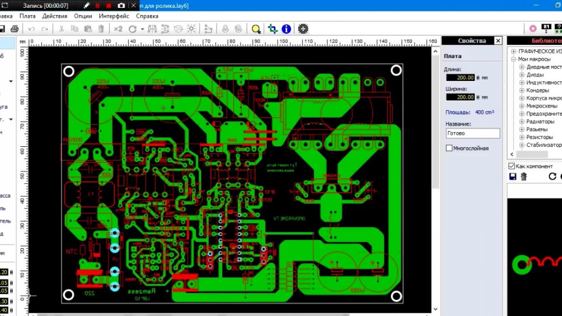
For this project, the author made a printed circuit board using the LUT method, which means that almost anyone can repeat the project on their own. So, now from the very beginning. The ideas themselves are quite simple. It was necessary to make a decent laboratory power supply with a minimum number of parts.
As a result, an uncomplicated scheme was born in the author’s head, and at first glance everything seems to work. For testing, a circuit board was drawn and manufactured. So, the unit started, but when trying to reduce the voltage, a terrible squeak appeared and transistors overheated.
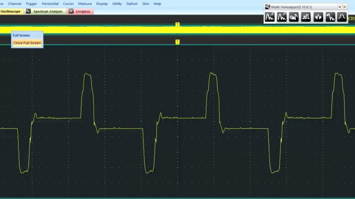
Since the author did not understand why this was happening, he installed the oscilloscope probe on the transistor gate and saw this picture:
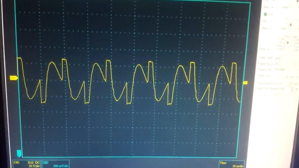
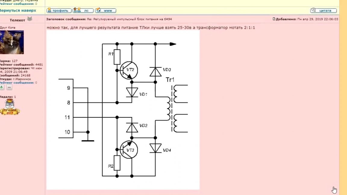
The author spent almost a month to find the cause of this problem, but in the end he found a solution on the Internet. The problem lay in the stored energy of the galvanic isolation transformer.There were several solutions. Here you can additionally load the windings of the TGR, or make another control circuit. The second option was chosen. The circuit was thrown by a member of the amateur radio forum under the nickname Telekot.
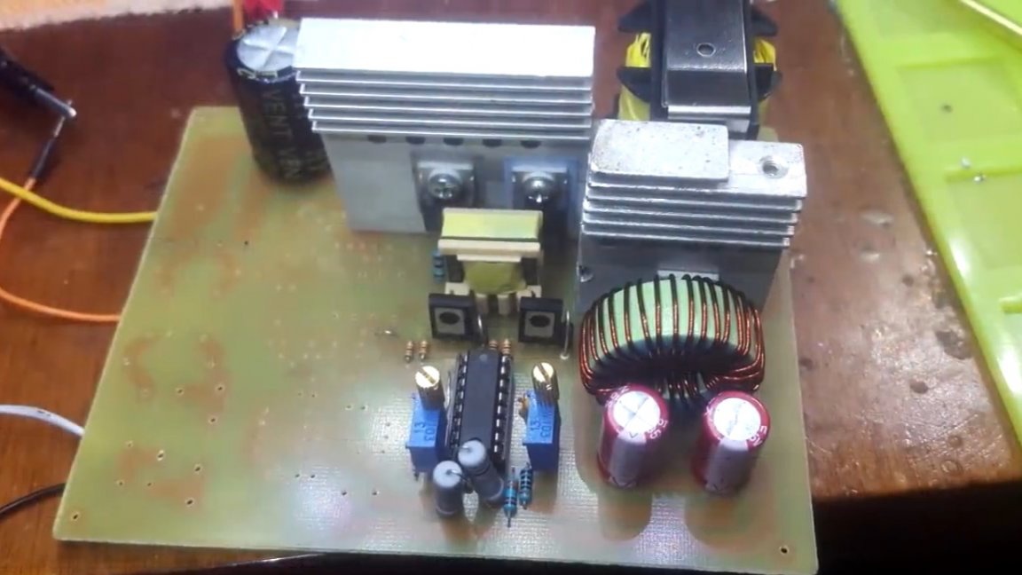
And after making the next board, everything started up.
The pulses are beautiful, the heating is almost completely absent. The snapper on the primary copes well, although it warms up a bit. And as already mentioned above, a problem arose that we could not overcome to the end. The problem is this: there is a squeak at low voltage. The thing is that when the voltage is set at the output from 0.6 to 2.5 V, the control pulses simply have nowhere to decrease and the microcircuit starts to pass them, therefore, the frequency decreases and as a result we begin to hear how the unit works.
In fact, there is nothing to worry about, with such a filling, the core is unlikely to be saturated. But let's try to solve this problem. So what are the possible options? The easiest way is to install a resistor in the load, but since we have an adjustable power supply, so at a voltage of 30V it can simply burn out.
The second solution is to reduce the number of turns of the throttle, so it will accumulate less energy and, therefore, the pulses should increase.
The author chose to dwell on the second option, but this is the so-called “crutch”. There is another solution to this problem and it is much better.
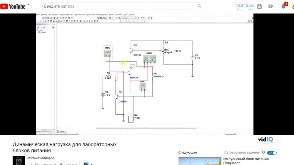
This solution is called dynamic load, it allows you to set the same current consumption at low and high voltage. But the author decided once again not to redo the board, so in this case he used the second solution to the problem.
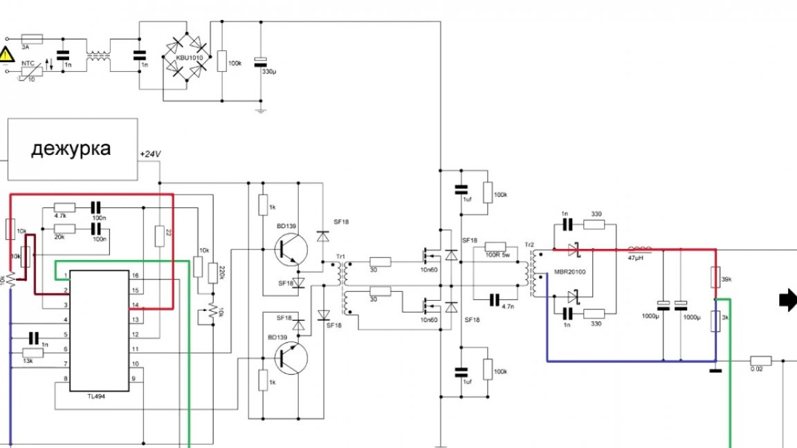
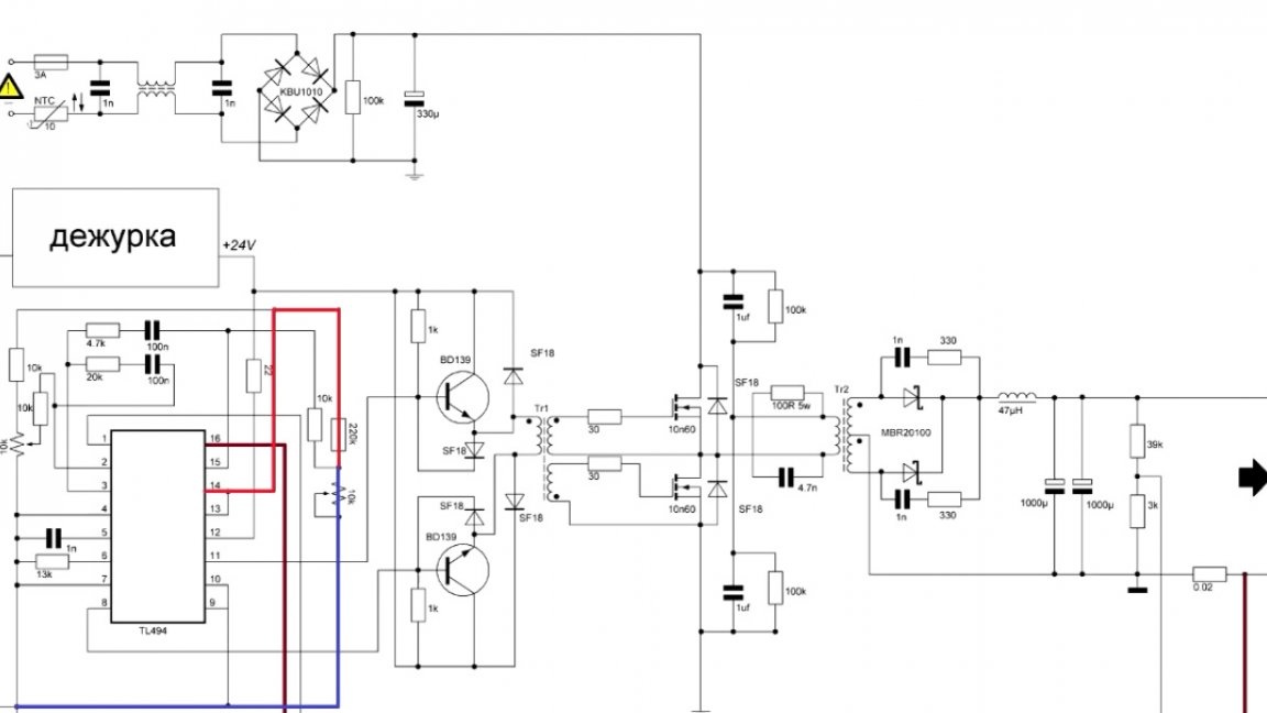
The final diagram looks like this:
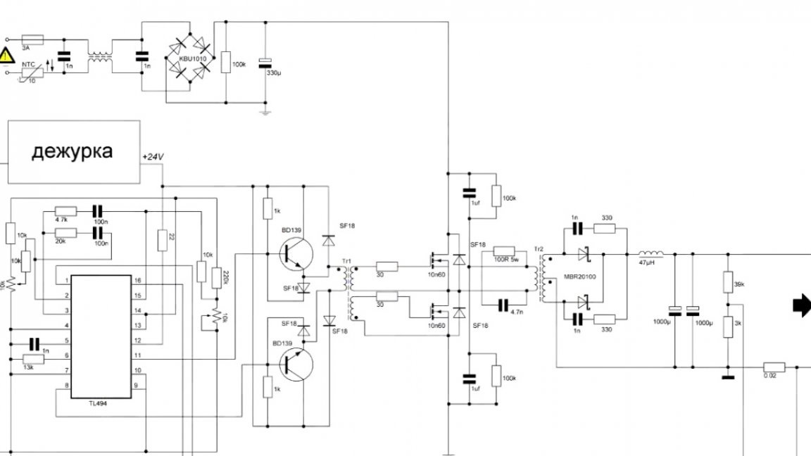
Here we have a duty room in the rectangle, you can make it any.
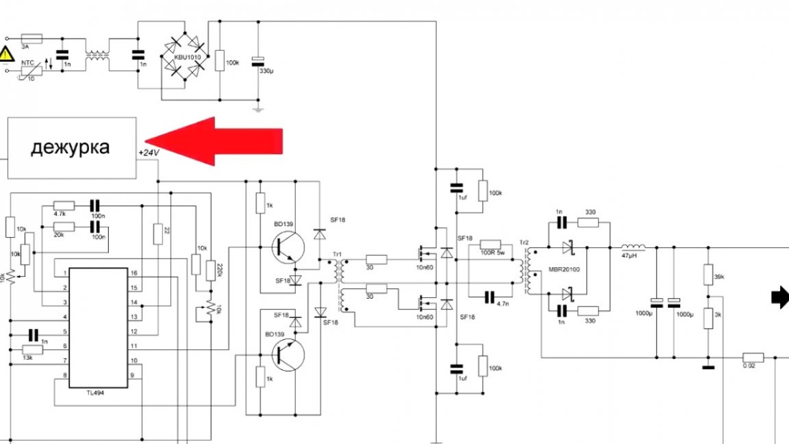
The author decided to use the duty room from his recent project, as it is simple and reliable.
We will not linger on duty, let's move on to the main scheme.
As you can see, there are not so many details here, but the functionality of a full-fledged power supply. The principle of operation is quite simple. The duty room provides power for tl494, it begins to form pulses that enter the TGR.
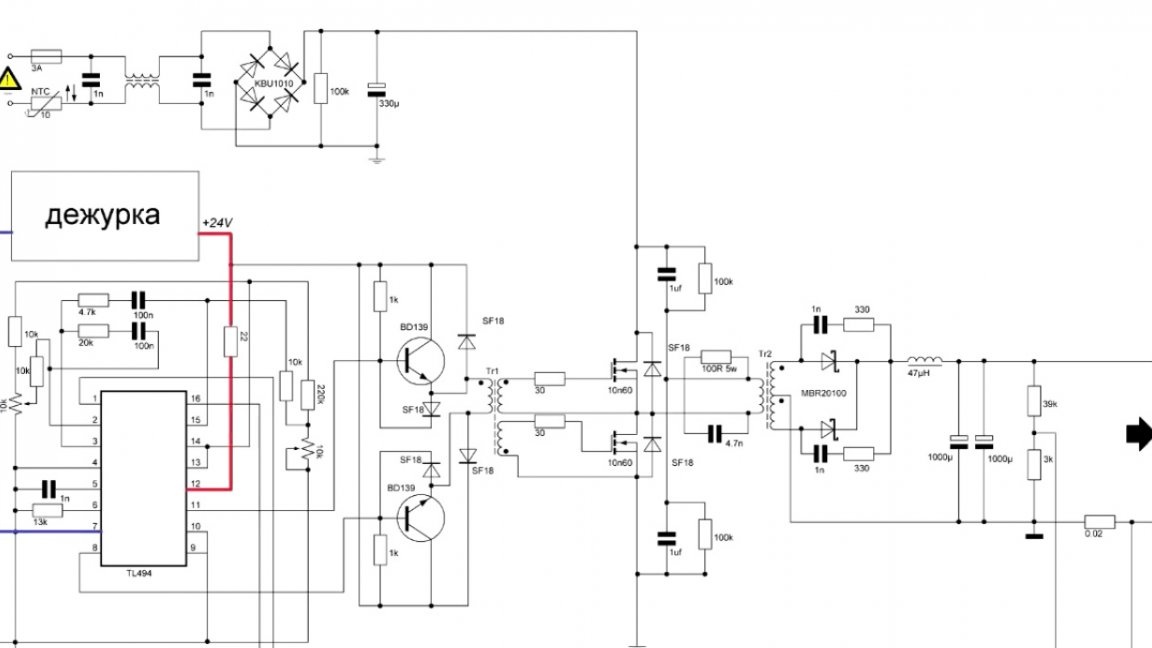
TGR in turn galvanically unbinds the low side from the high. Pulses from TGR arrive at the transistor gates in antiphase.
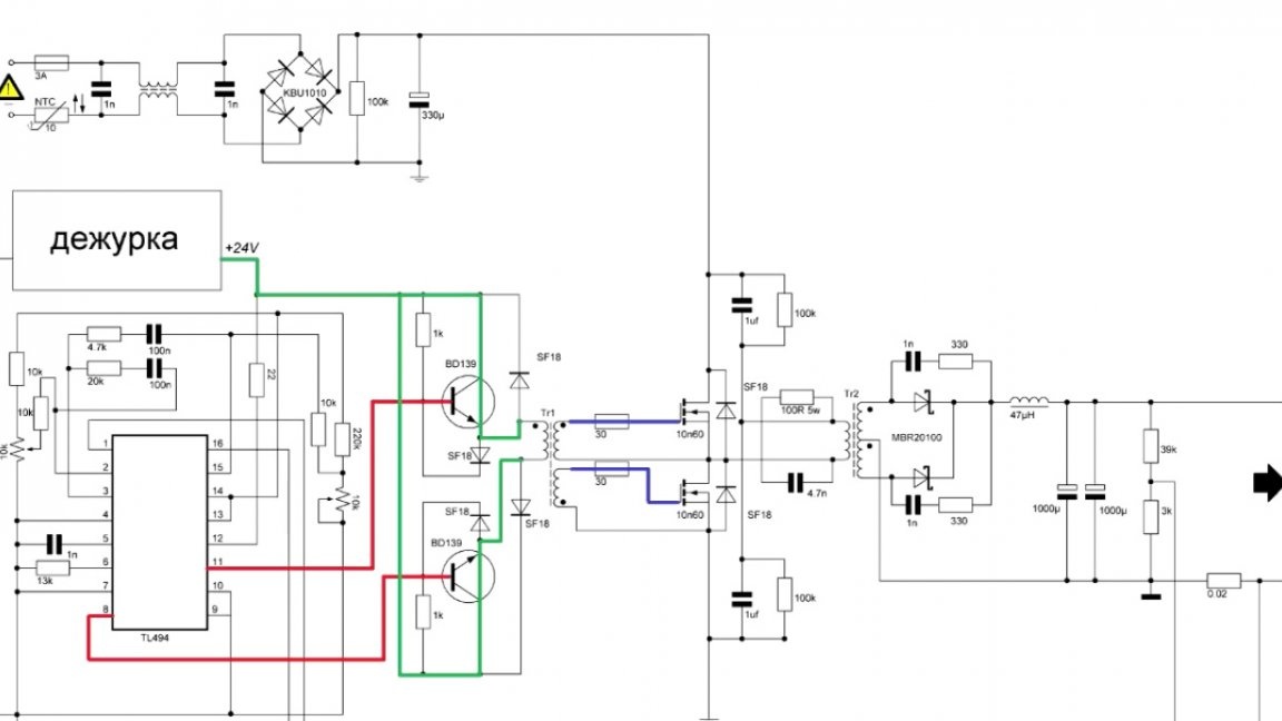
Well, then the standard half-bridge scheme.
As you can see, the principle of operation is quite simple. The next step is to make a printed circuit board.
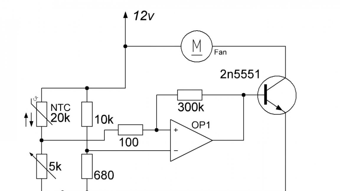
The board provides control of the cooler by temperature, but you can remake the board and make the cooler rotate constantly, and put a dynamic load here, this is your choice.
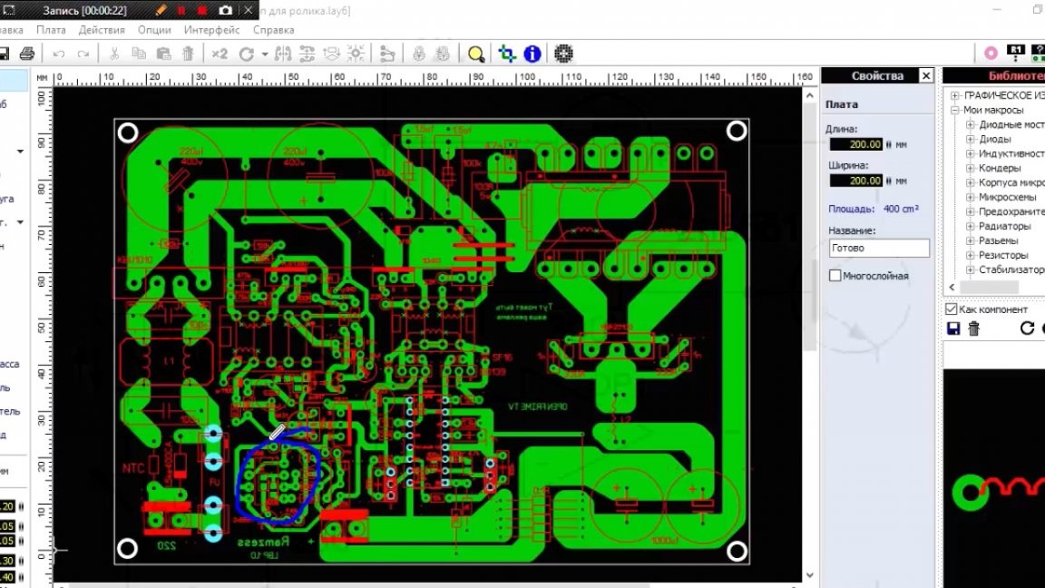
The fee is like this:
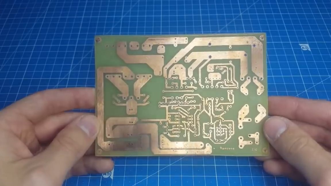
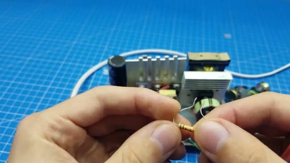
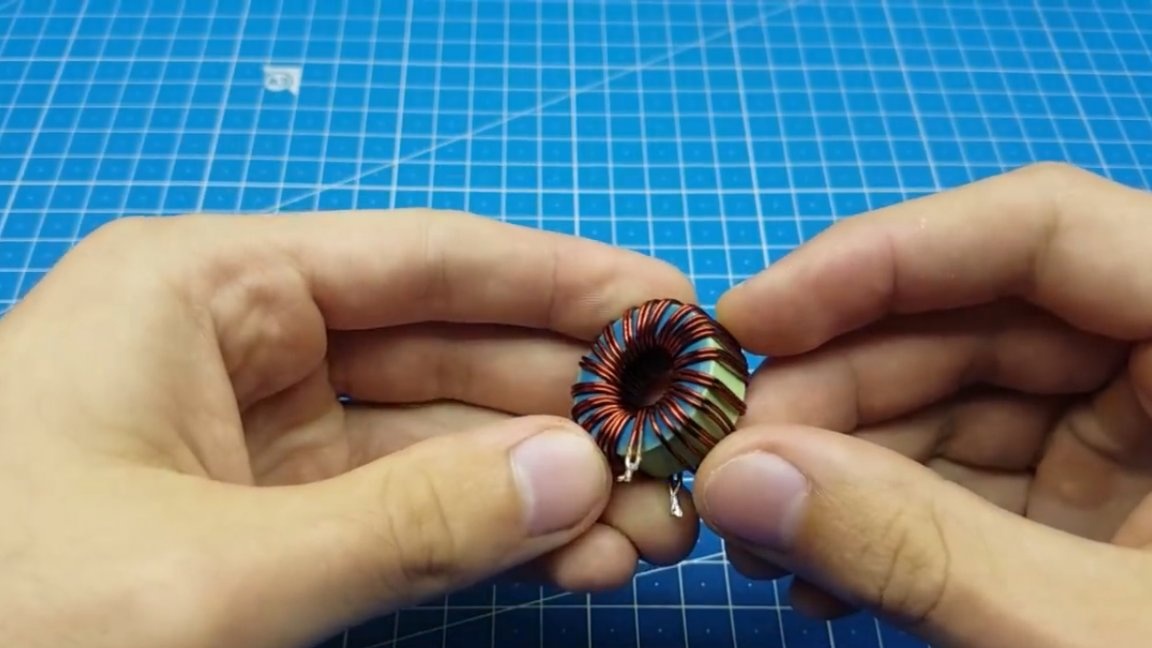
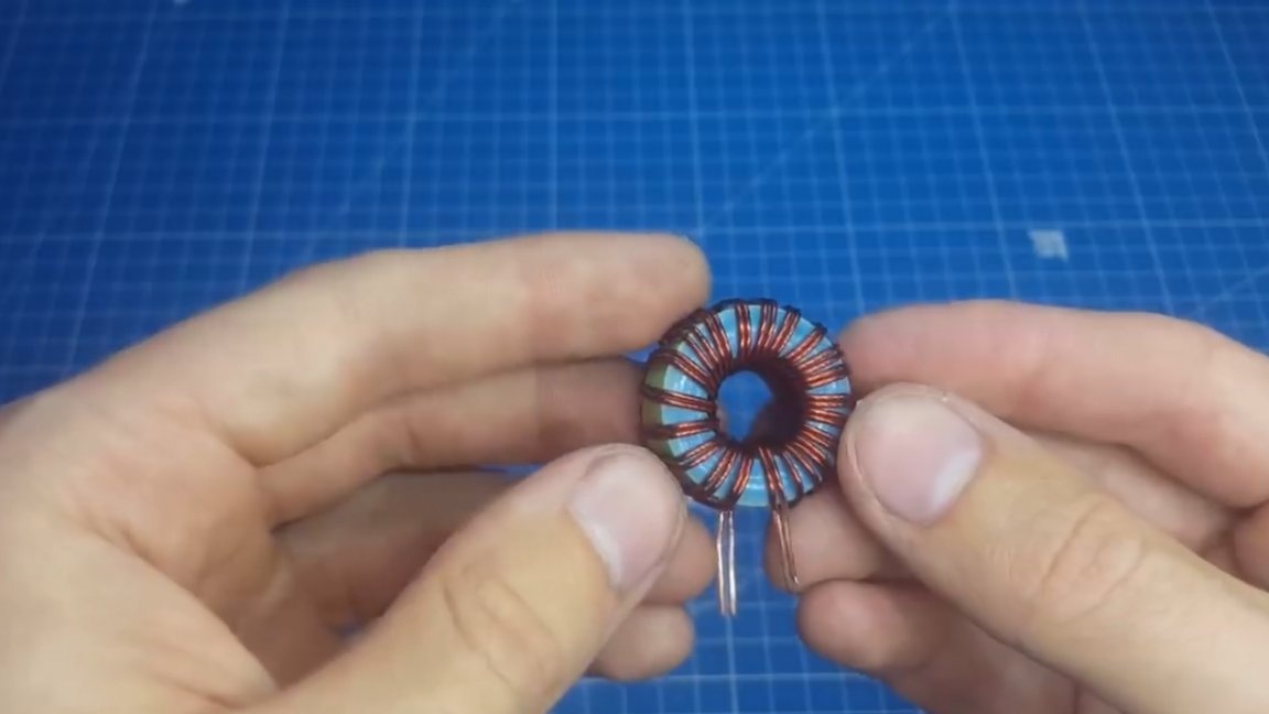
Now it needs to be soldered. When all the elements are in place, we proceed to winding work. Let's start with the chokes. The input choke protects the network from noise, which is directly emitted by the power supply itself. We will wind it on a ferrite ring with a permeability of 2000, the diameter of the ring is 22 mm. We wind 2 to 10 turns with a 0.5mm wire.

Further output choke. At first, about 15 turns of a millimeter wire doubled on a ring of powdered iron were wound, but in the end they had to be reduced to 7, as a result of which the squeak almost completely disappeared.
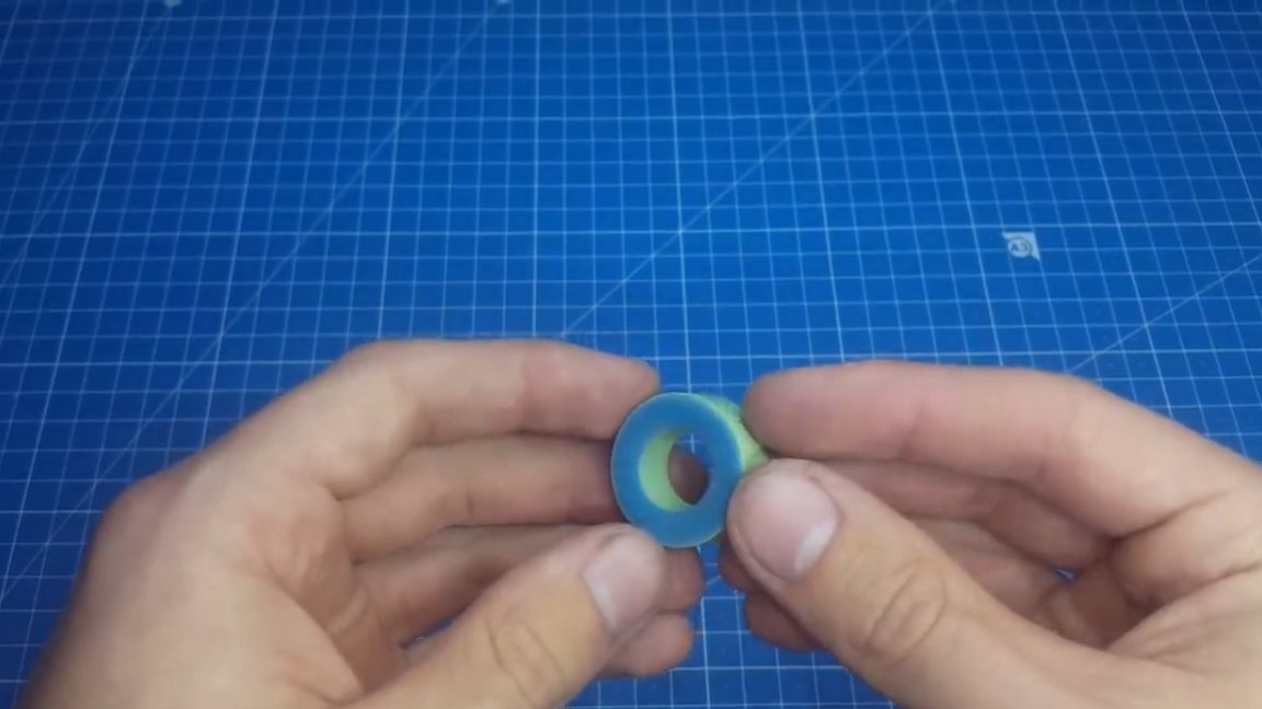
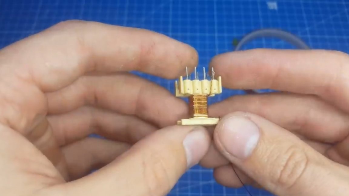
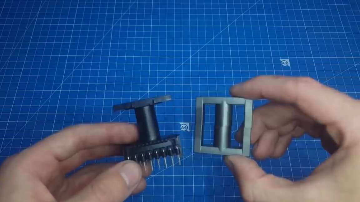
The next step is to make a TGR. For this, the author used such a frame and an E-shaped core E16, but with the same success it can be wound on a ring.
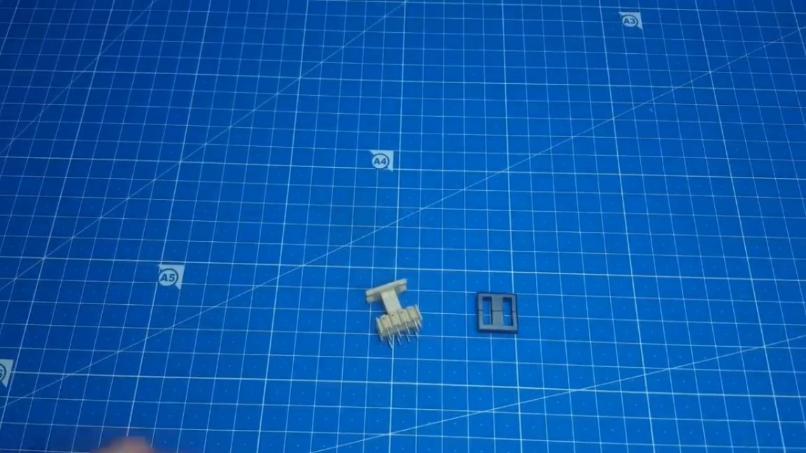
The core is made of ferrite with a permeability of 2000-2200. We make the necessary calculations using the Starichka program.
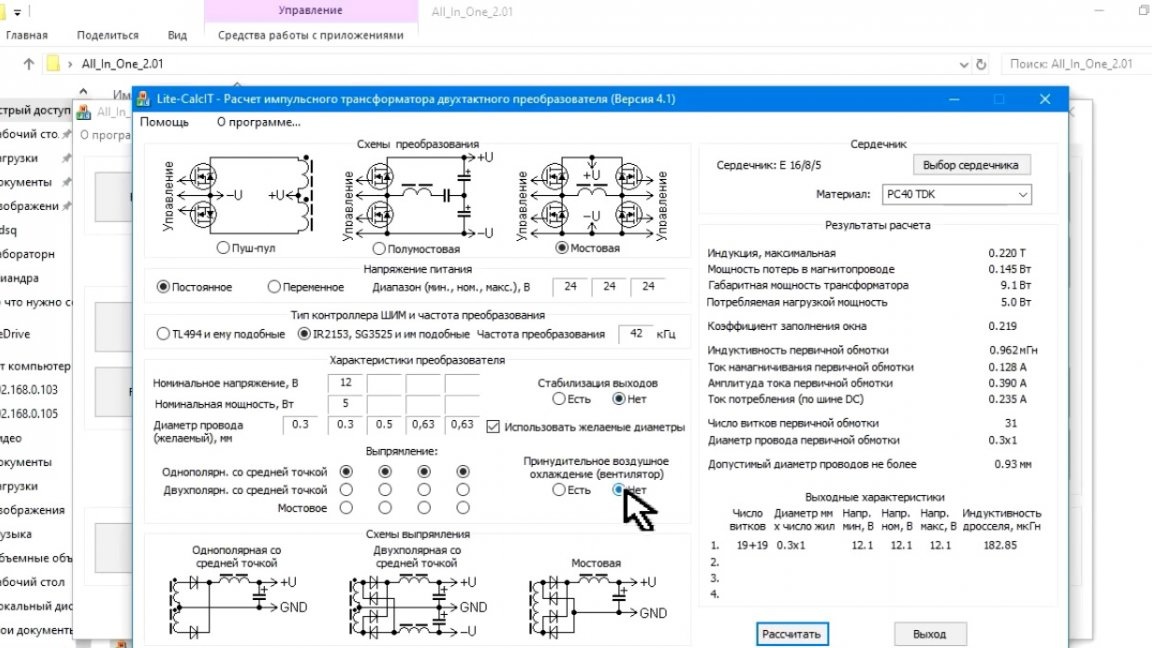
We know the input voltage, but we want to get 12-15V at the output. We choose a bridge control circuit, because all the voltage will be applied to the winding, and not half as in the floor of the bridge.
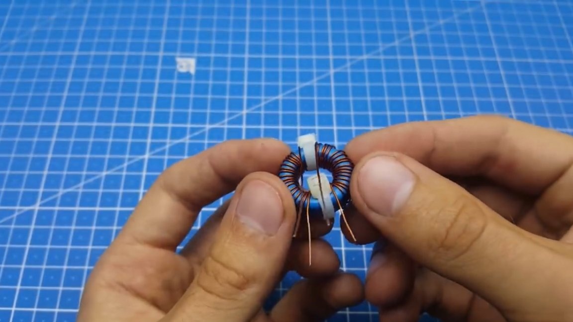
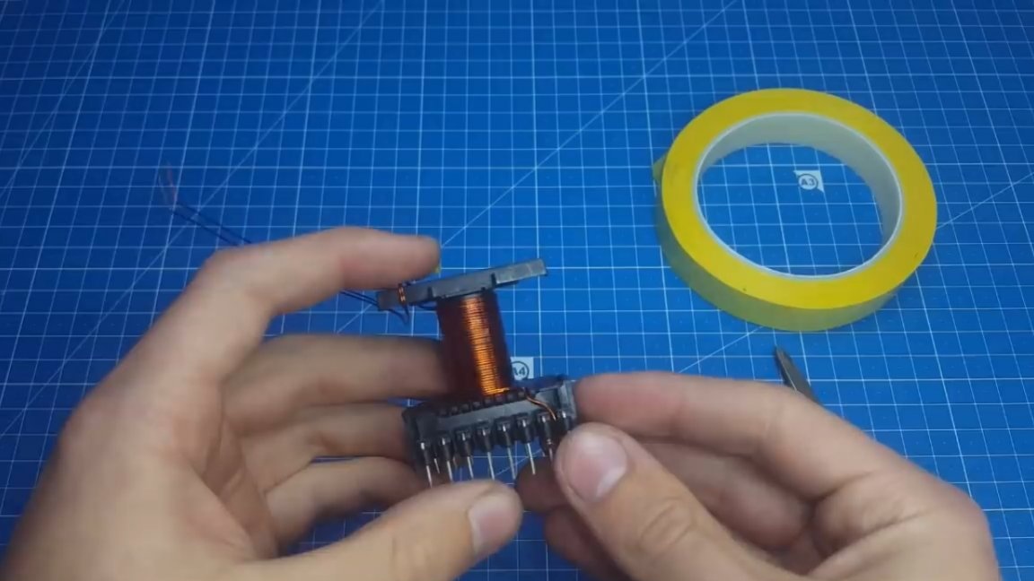
To improve magnetic coupling, the primary winding must be divided into two parts.Half at the bottom and half on top of the secondary.
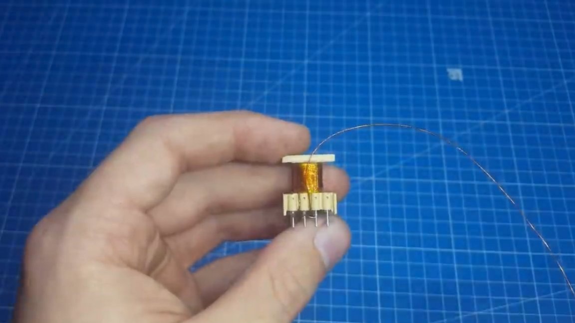
We immediately wind the secondary into 2 wires nearby, this will avoid voltage distortion. Also one of the problems in this case is phasing. It is necessary to clearly distribute the beginning and end of the windings in accordance with the points on the board.
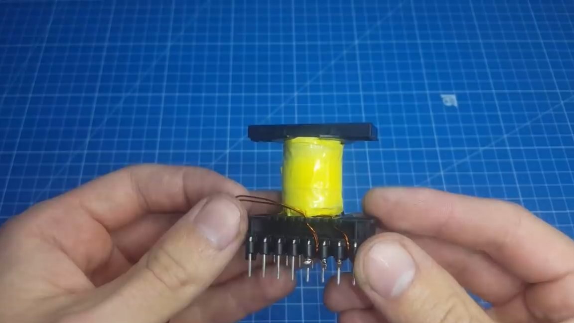
Now it remains to wind the main transformer. Initially, the calculation was made for a voltage of 36V, but the squeak was already up to 5V, so I had to rewind the transformer to 30V of the output voltage, plus a margin for stabilization.
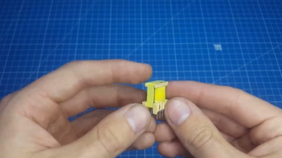
There is nothing complicated in winding a transformer. We also divide the primary into two parts, and the secondary between them. At the same time, we try to wind the coil to the coil, avoiding overlaps as much as possible, thus increasing the quality factor of the transformer. Do not forget to isolate the windings with a special tape.
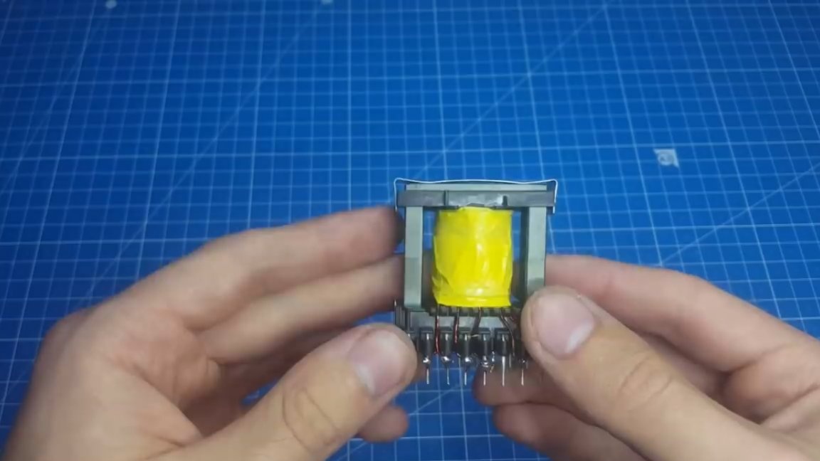
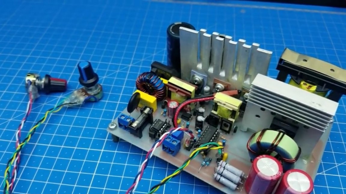
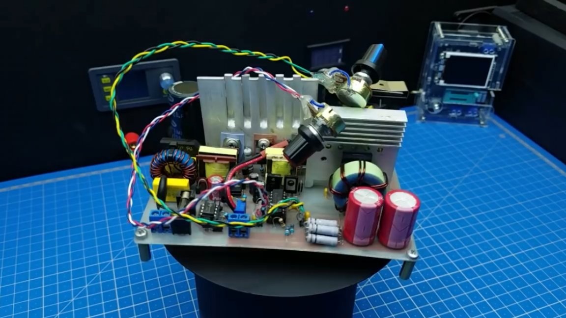
The winding is over, we solder the resulting products on a board and our homemade laboratory power supply is completely ready.
Now it's time for the tests. We connect the multimeter to the terminals of the power supply and begin to regulate the voltage.
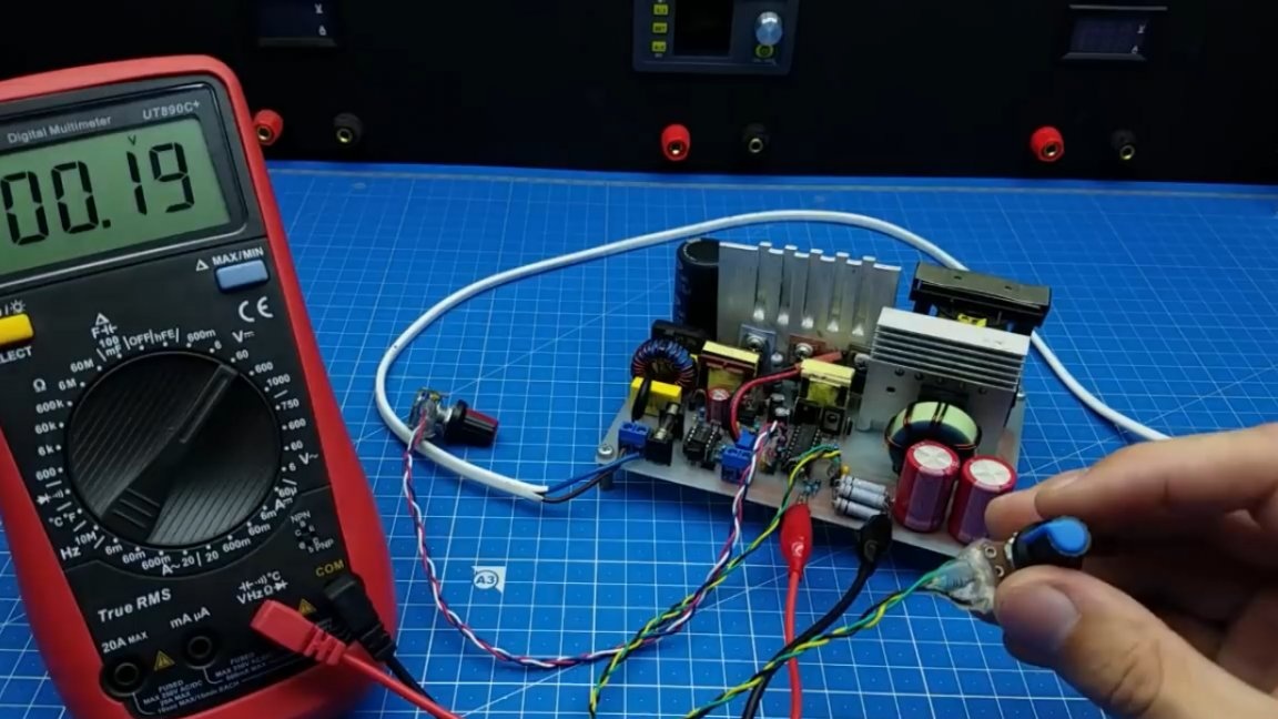
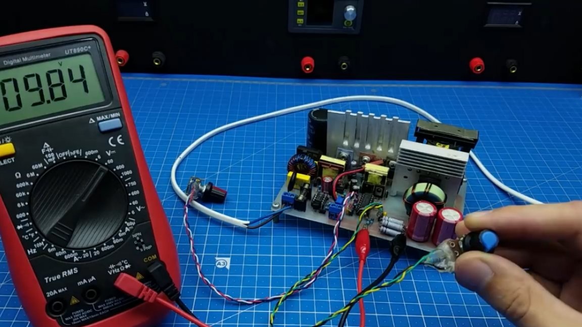
As you can see, there are no problems with this, everything is fine. Now let's connect the load. An incandescent lamp at 36V with a power of 100W will act as a load.
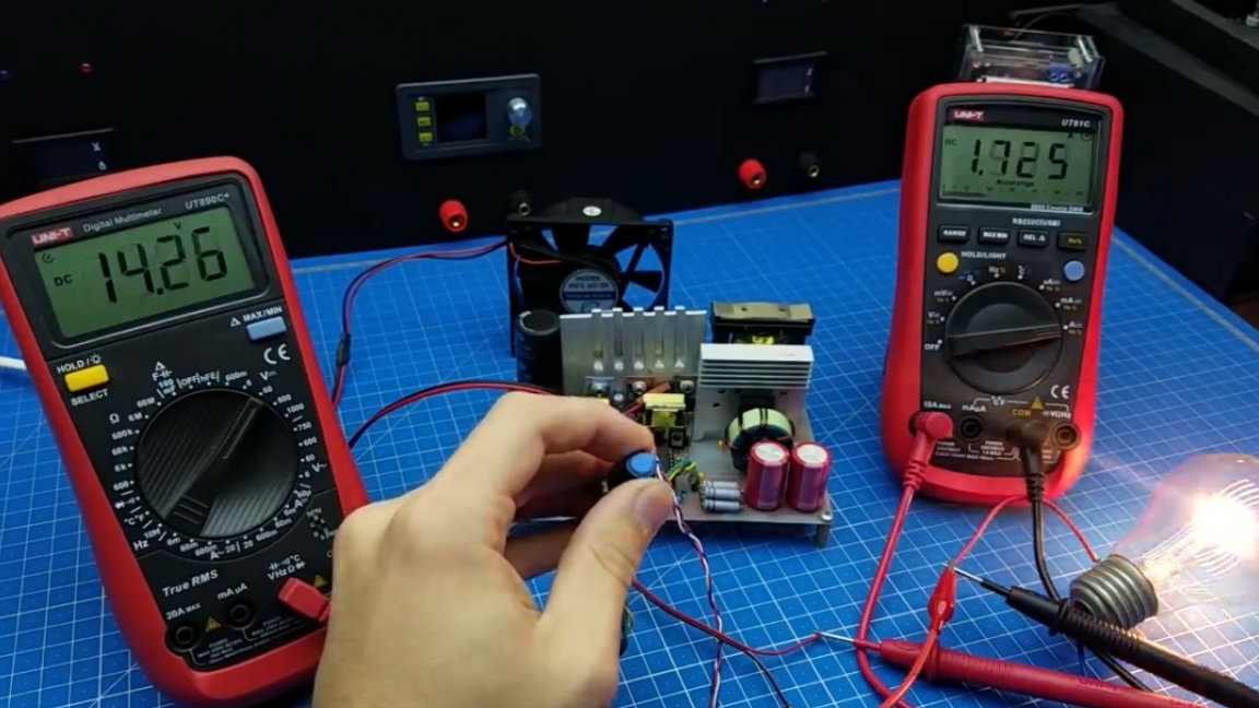
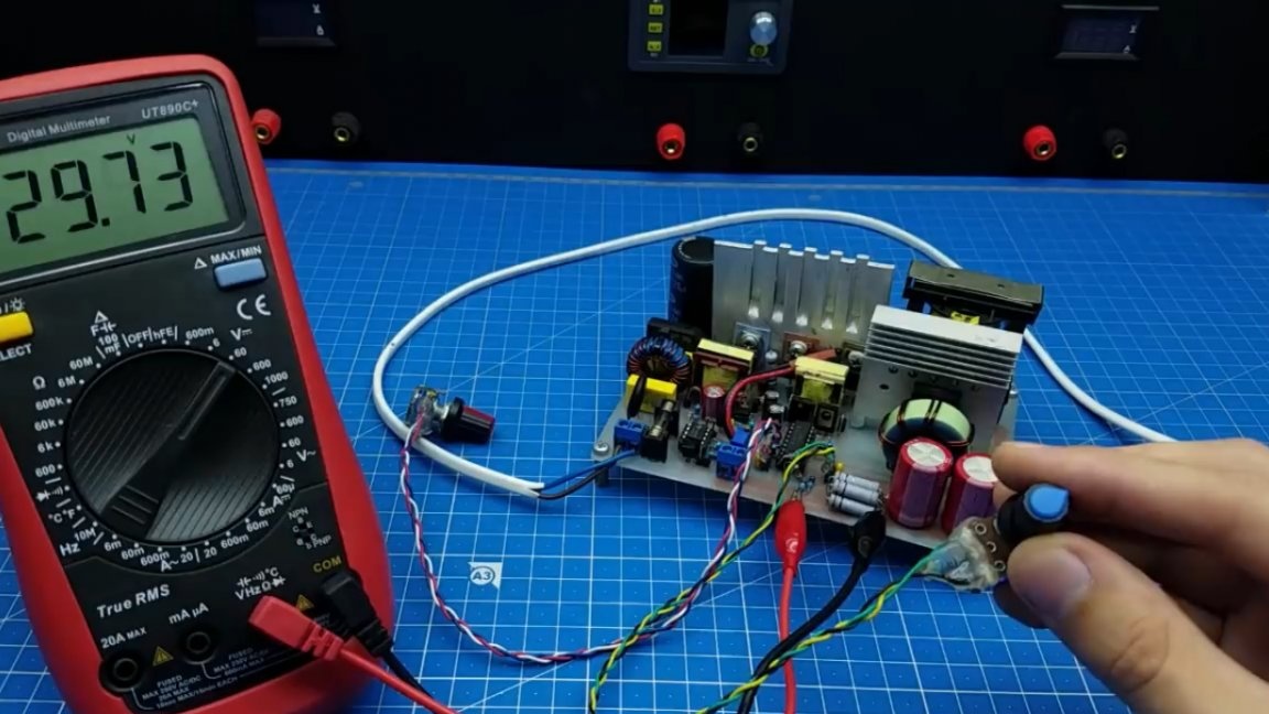
As you can see, the run over the entire voltage range was successful, the unit did just fine. Now we try to limit the current. To do this, it is necessary to rotate the second potentiometer and the current adjustment also works properly. As mentioned above, in this version of the board thermal monitoring is installed, let's check its operation, too. To do this, we connect a cooler to the board and start heating our thermistor with a hairdryer.
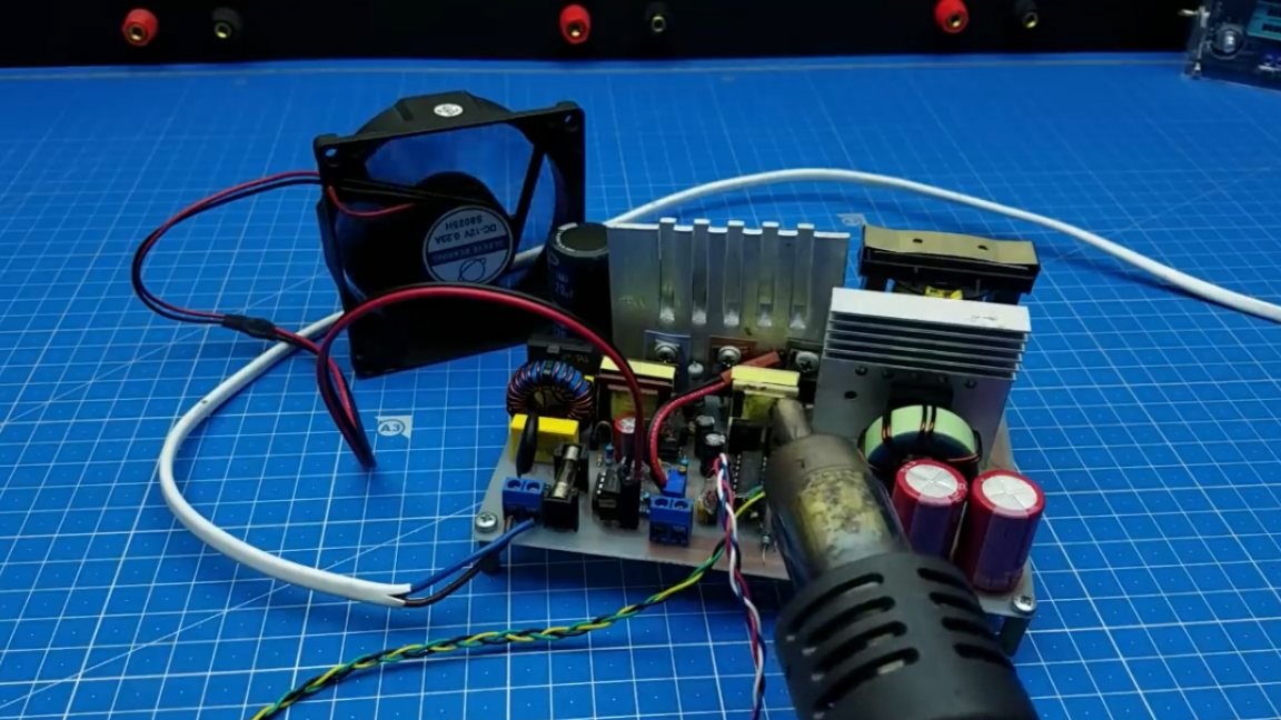
As you can see, when a certain temperature is reached, the cooler turns on and starts to rotate, and the board cools. Summing up, we can say that this unit is not ideal, and it is better to use it as charging or power for unpretentious circuits, although in general it turned out well. Thank you for attention. See you soon!
Author's video: