
First, let's understand the difference between the octocopter and the quadcopter. In addition to the name, this is also the number of engines on the rails. Those. quadrocopter - four engines, octocopter - eight. This is also true for the hexacopter - six, tricopter - three, etc. If the guides, for example, are four (X), and eight engines, then this is still an octocopter, but is designated as X8. Those. on four rails, eight engines.
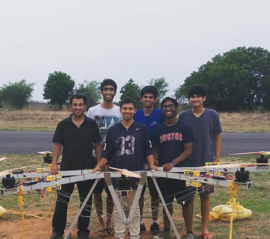
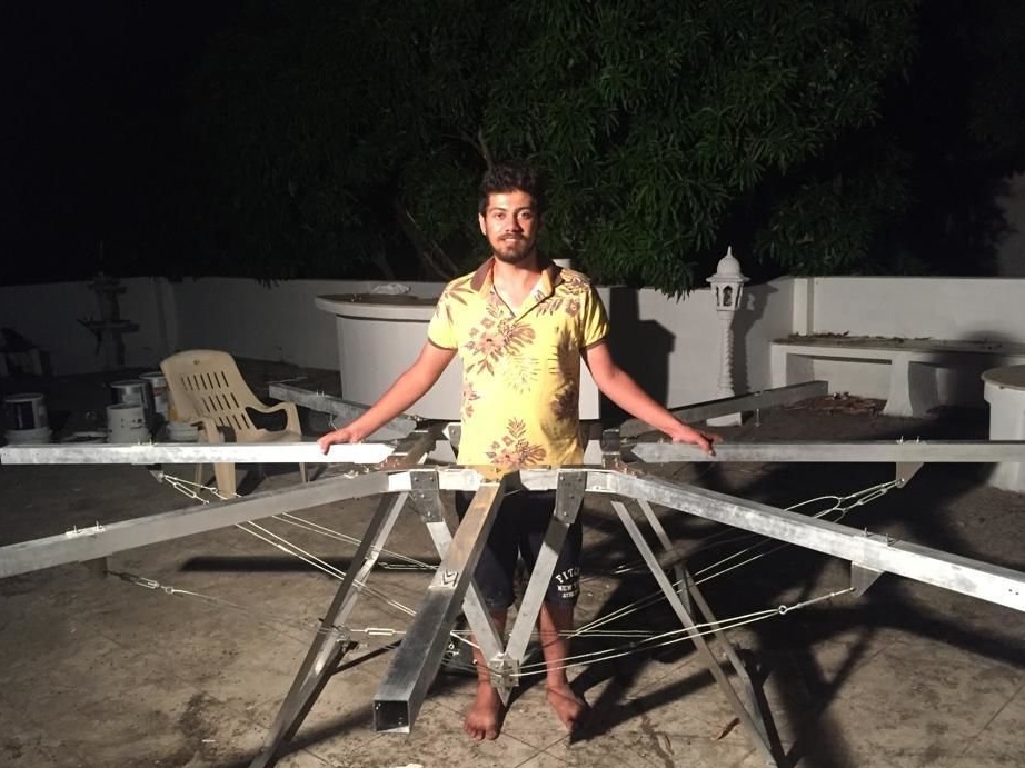
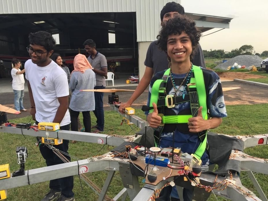
Basically, numbers with a prefix for copters are aircraft that are controlled by the operator’s radio signal from the ground. A student from India decided to go further and make an octocopter capable of raising a person into the air. This is not a cheap project. The financing was taken over by the educational institution.
Tools and materials:
- Engines Turnigy CA170 Motors - 8 pcs;
- Controller Turnigy Fatboy 300A - 4 pcs;
- Turnigy 200A HV controller - 4 pcs;
- Transmitter Hitech XG11 Tx / Rx;
-Flight DJI A3 Pro controller;
-Flight controller DJI Naza M V2;
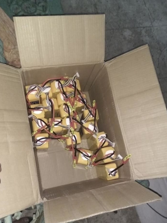
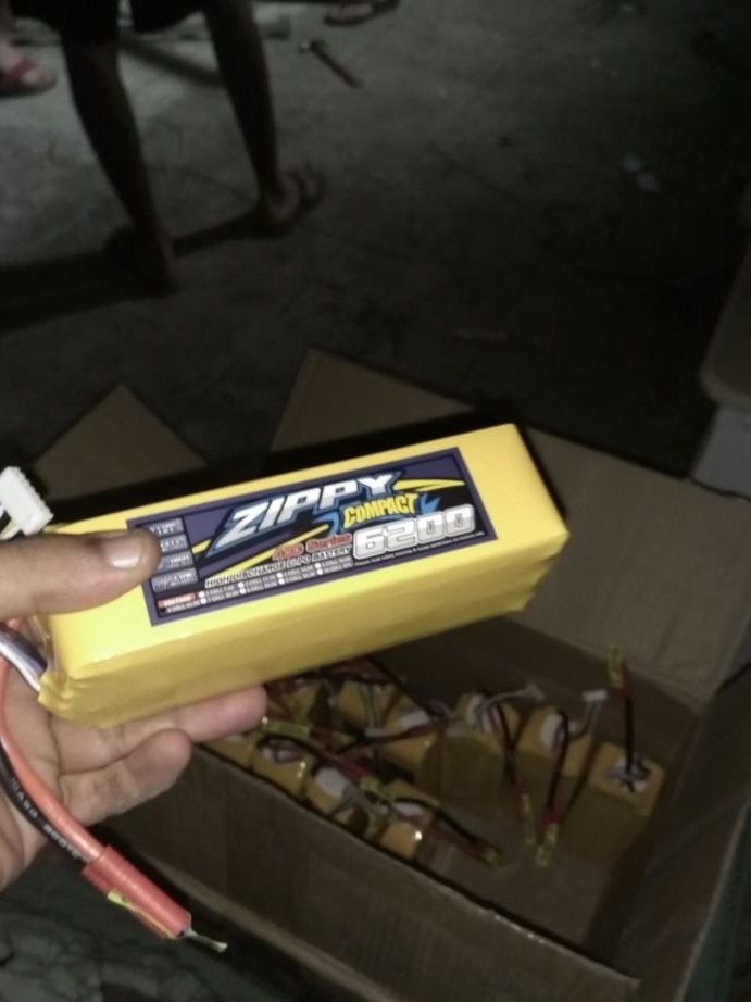
- Battery Zippy 22.2V 5Ah 40C LiPo - 16 pcs;
- Charger 6s LiPo Charger;
-XT150 connectors - 50 pcs;
-Wire 8AWG Sillicone Wire - 10 meters;
Servos;
-Ball for playing squash (Squash Balls) - 4 pcs;
- MDF sheet 25cm x 50cm x 2mm;
-Drill;
-Angle grinder;
- Screwdrivers;
-Spanners;
-Pliers;
-Laser cutter or band saw;
-Assortment of nuts 4mm, 6mm and 8mm, bolts and washers;
-Burner;
-Light-emitting diode;
-Soldering accessories;
- 2 and 3 mm steel wire;
-Telrep screw 100mm-200mm - 40 pcs;
- 40 hooks and eye bolts;
-Tachometer Turnigy RPM;
-Power Analyzer (Turnigy Wattmeter / Ampmeter);
-Battery controller;
- Aluminum profile pipes;
-Aluminum plate;
-Double sided tape;
-Welding machine;
-Roulette;
-Computer with Fusion 360;
- Battery 11.1 V 2200 mAh LiPo 30C;
-Dense fabric 1.2m x 1.2m;
- Strong thread and needle;
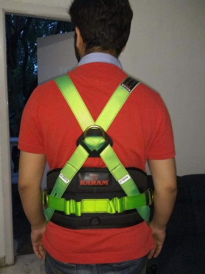
-Seat belts;
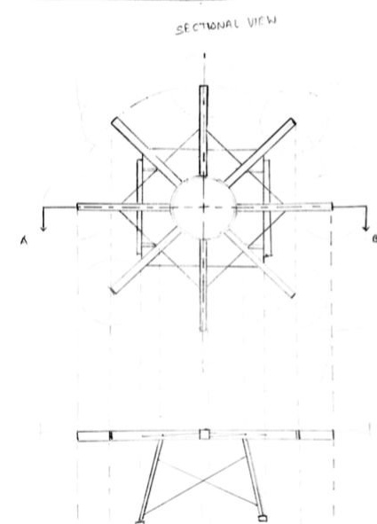
Step One: Design
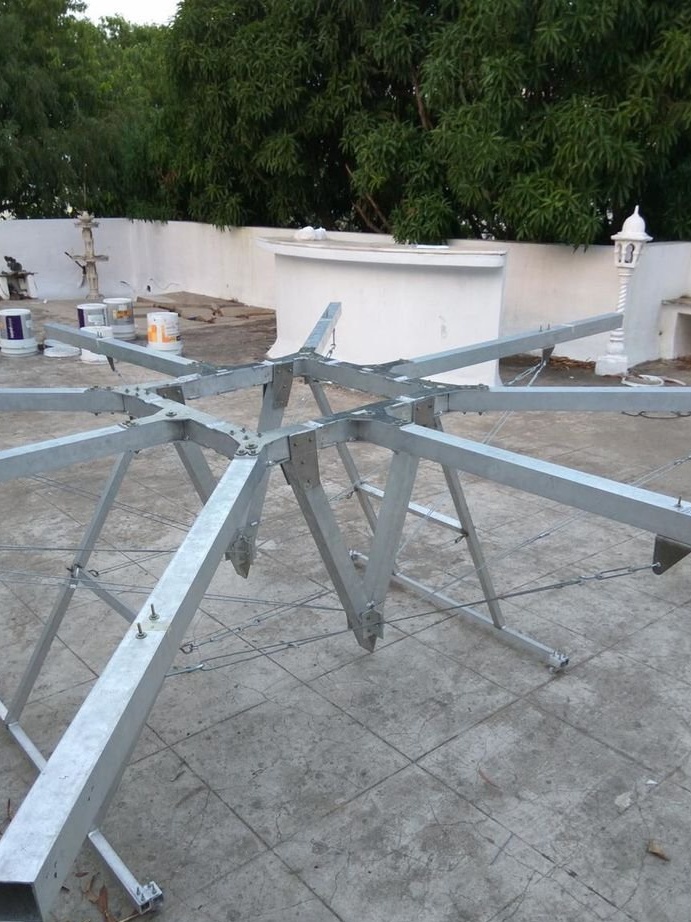
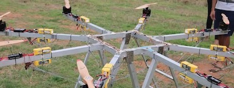
When developing a manned octocopter, the master considered various configuration options, and X8 and H, and T, but came to the conclusion that the most optimal, for various reasons, would be the design of the octocopter, according to the traditional scheme.
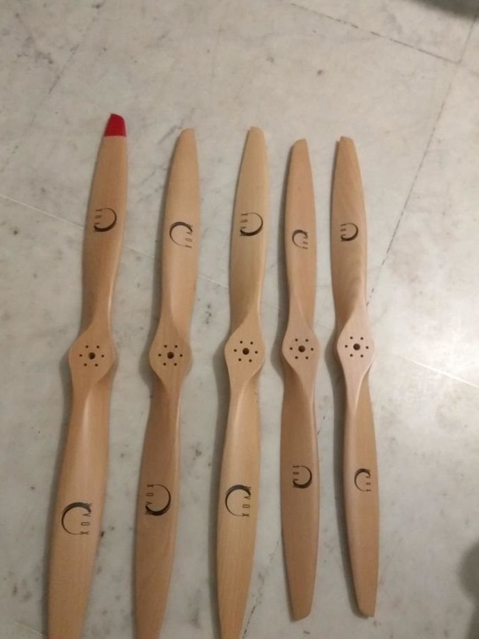
Then it was necessary to find out what the size of the octocopter should be. The calculations were made using CAD models on the Fusion 360 as an example. The existing screws were taken into account in the calculations. The optimum turned out to be a diameter of three meters, a height of one meter. Inner basket, for a person 55x55 cm.
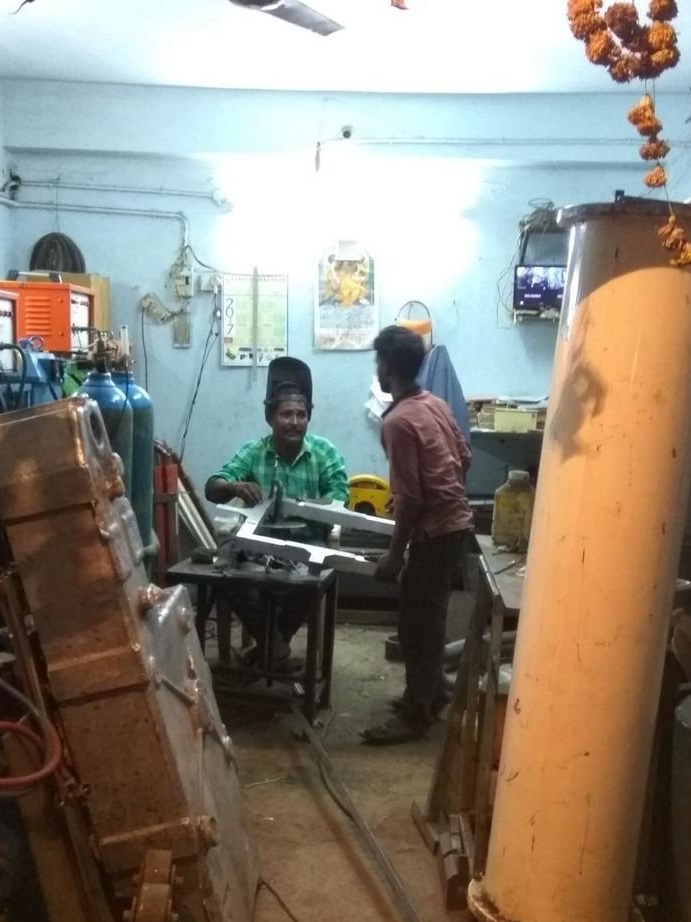
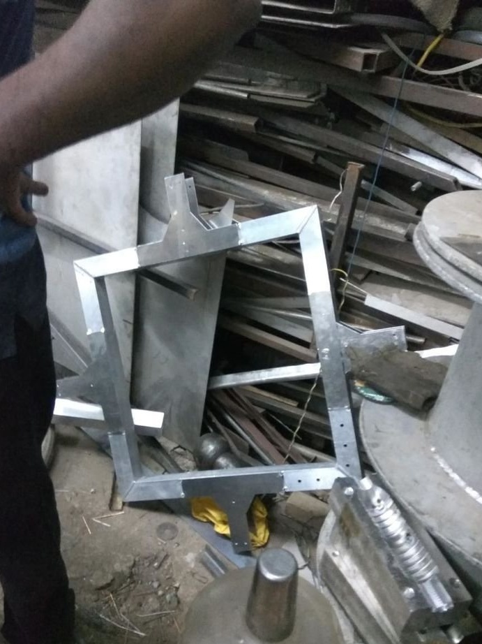
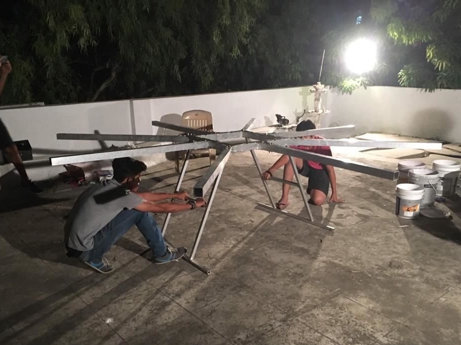
Step Two: Shopping Cart
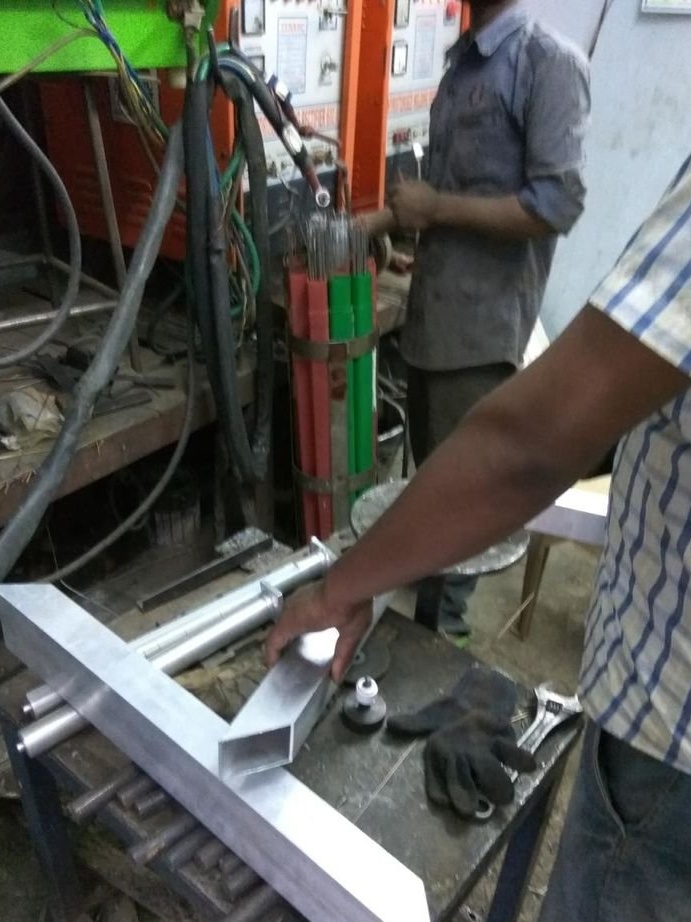
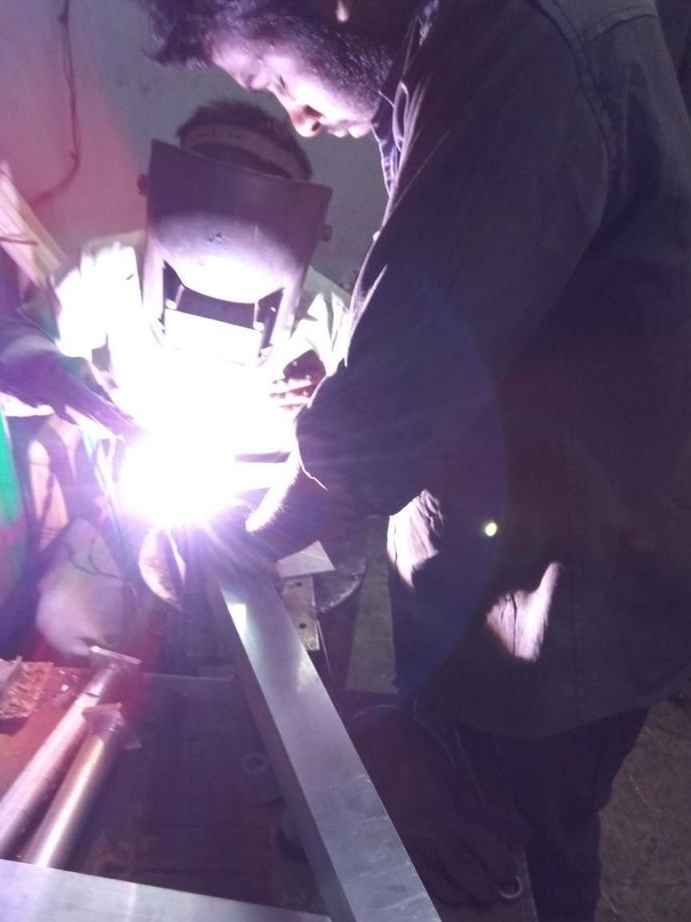
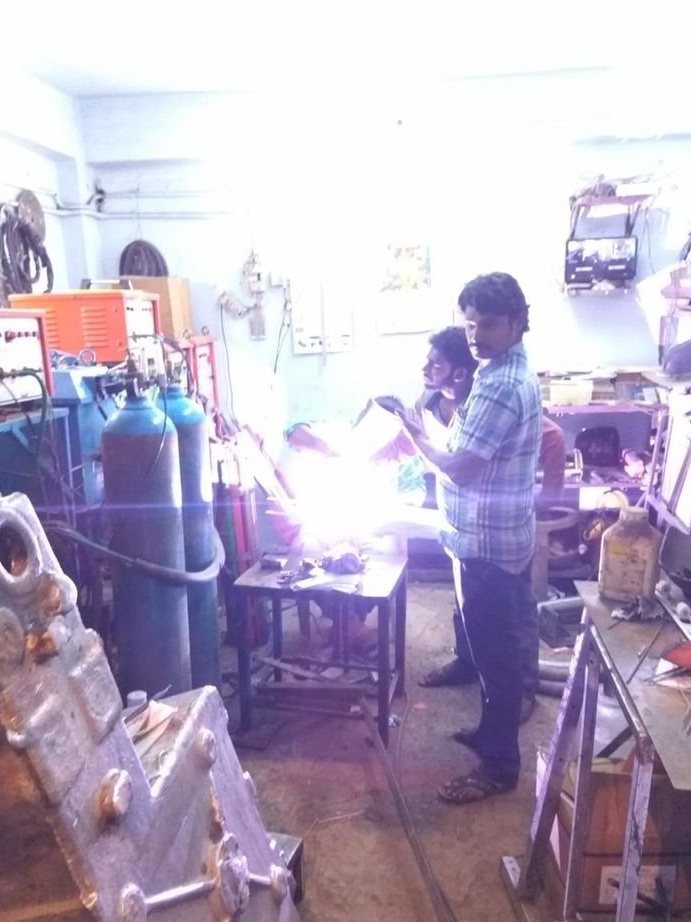
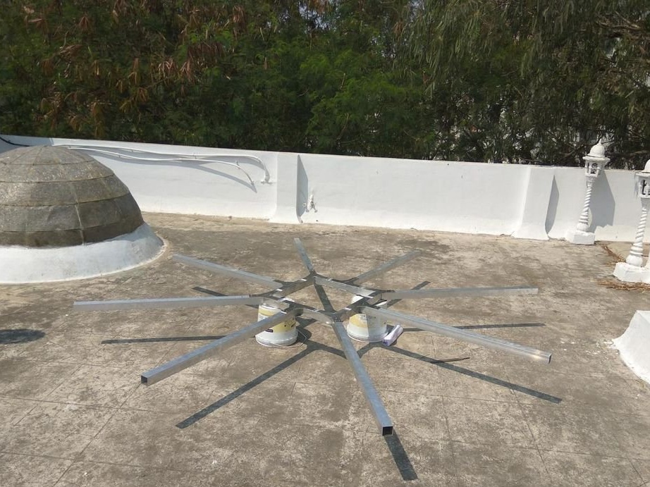
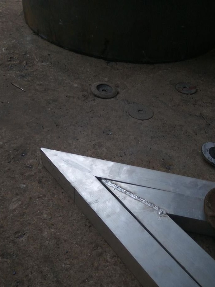
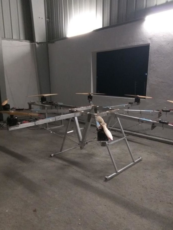
The frame was welded from an aluminum square profile with a shelf of 50 mm and a wall thickness of 2 mm.
The profile was cut and welded. The seams are cleaned.
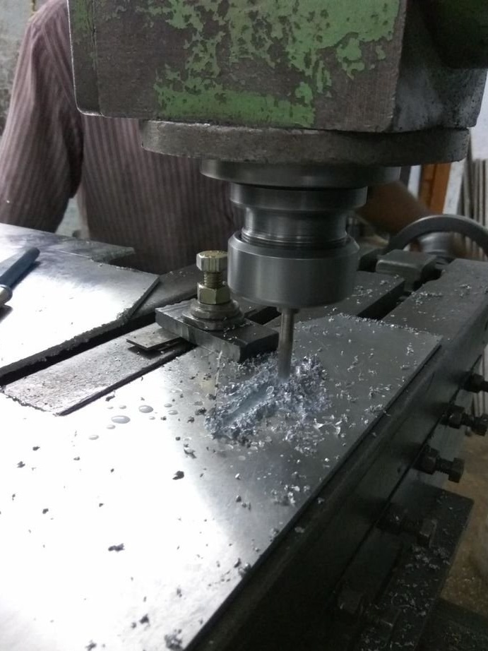
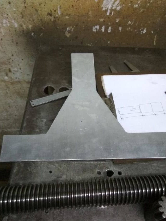
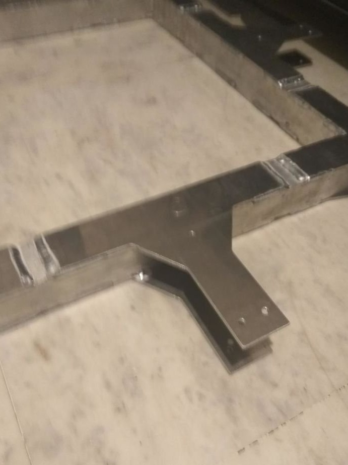
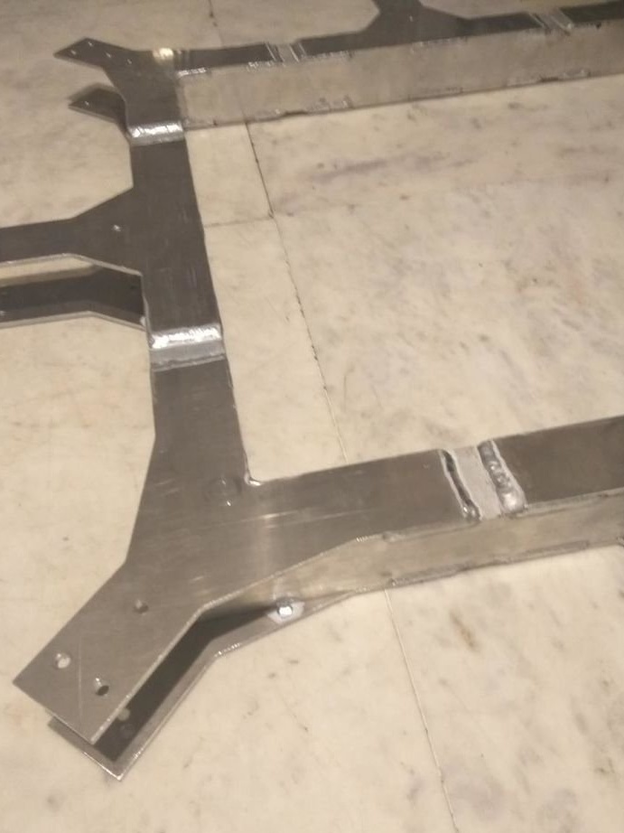
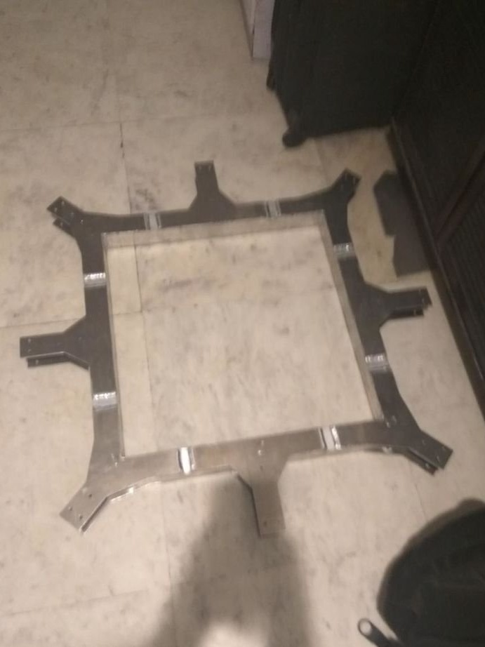
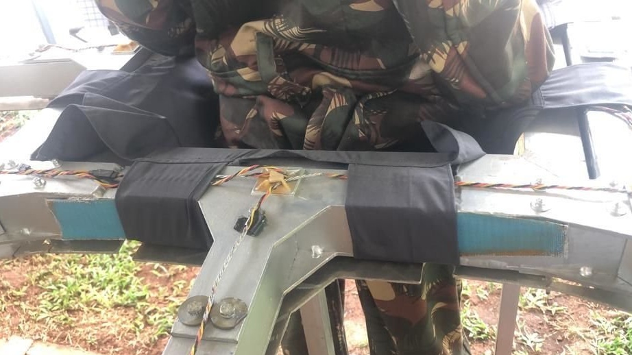
Step Three: Mounting Plates
For brackets, the master used aluminum plates of 1.5 mm. There are eight brackets in total, four in the corners, and four in the middle of the frame. The length of the arm shoulder and the supporting part is 15 cm each. The brackets were designed in the Fusion 360. The plates were cut with a milling cutter. Mounting holes are drilled in them. Then the brackets were welded to the frame.
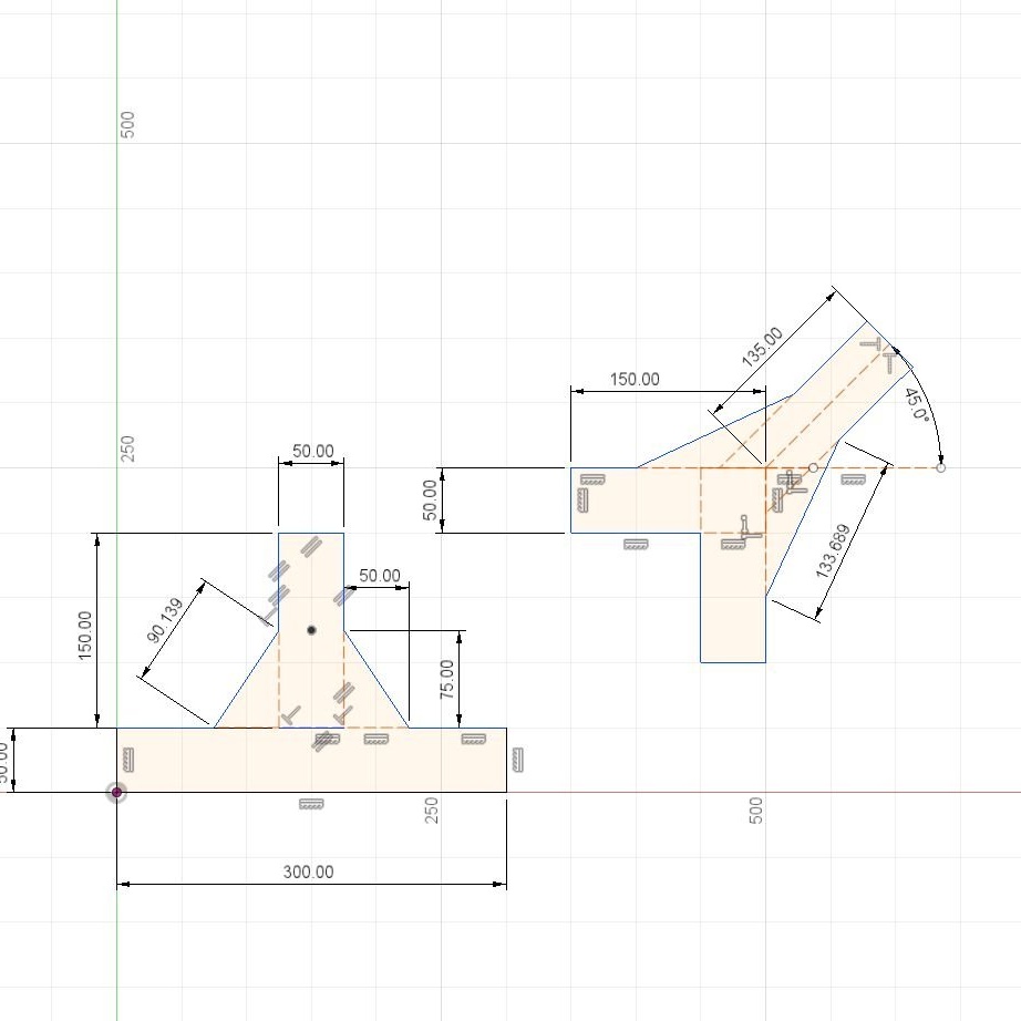
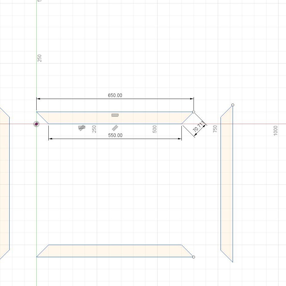
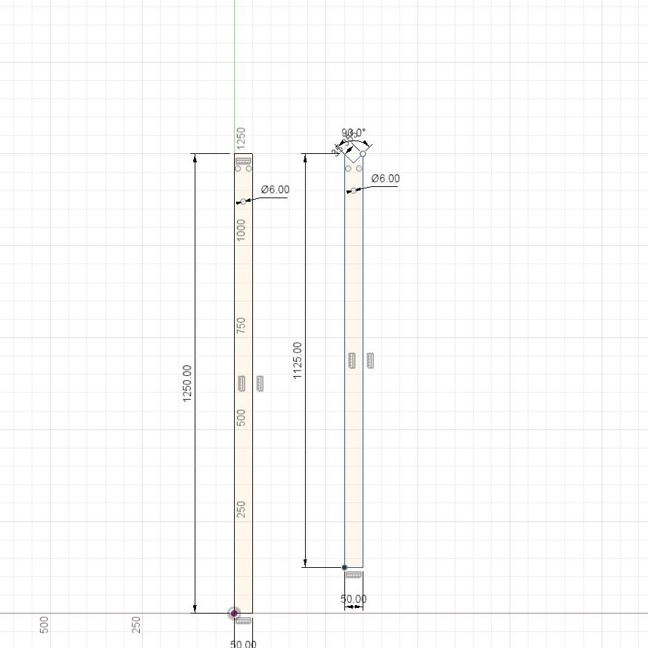
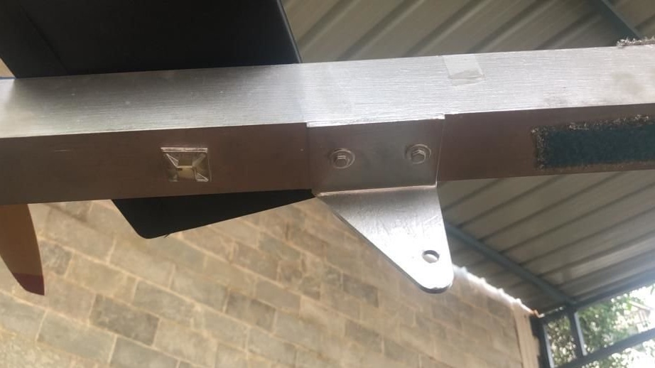
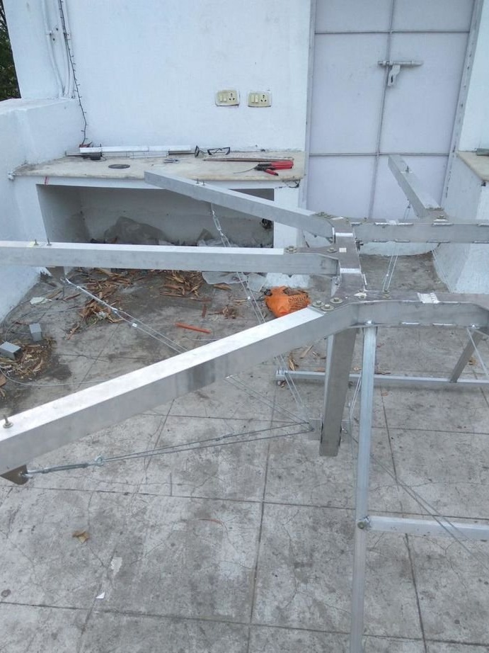
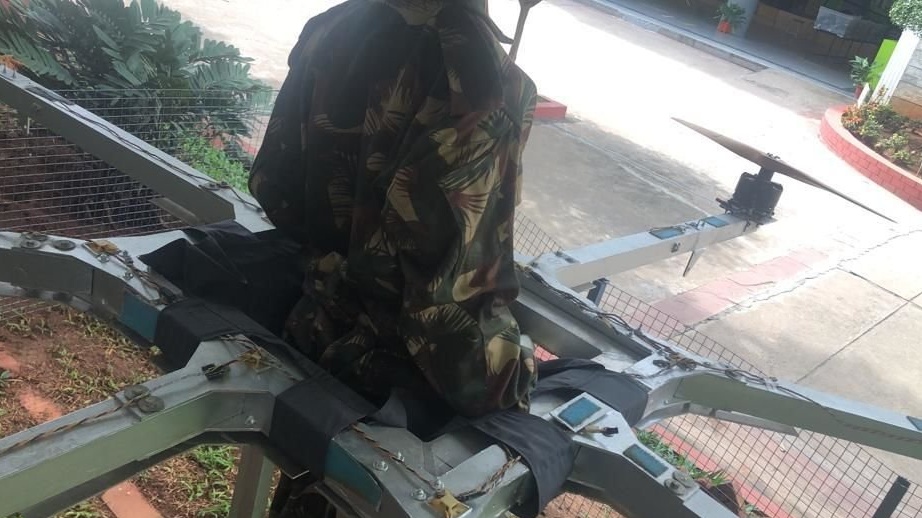
Step Four: Carrier Profile
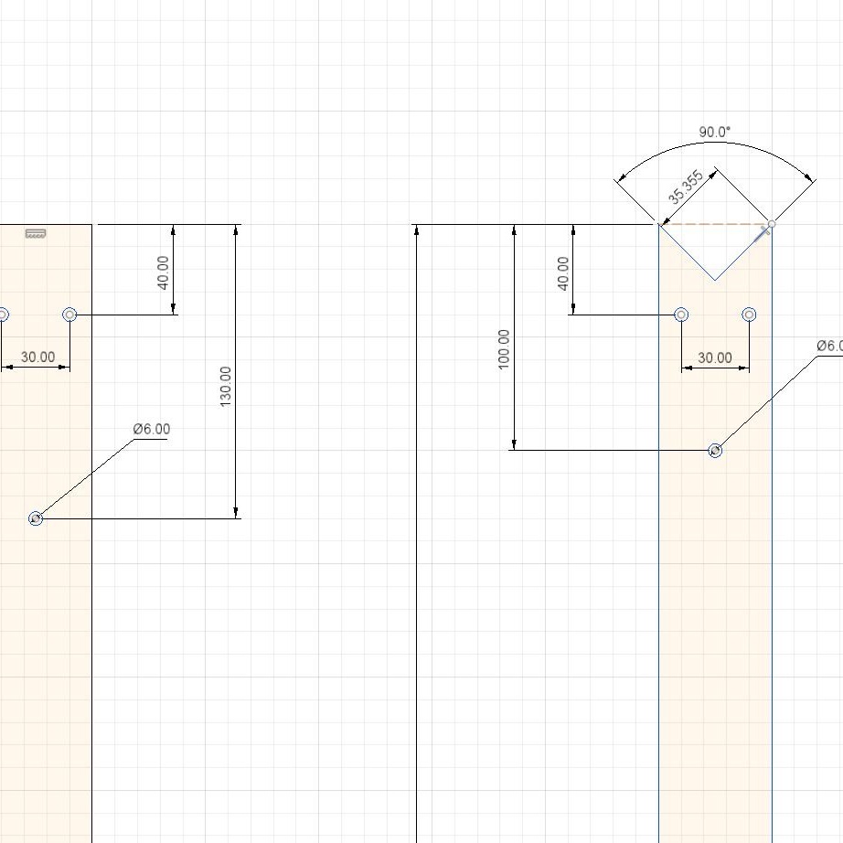
These profiles are attached to the brackets and motors are installed at their ends. The profiles are square, 50 X 50 cm, and have different lengths. Profiles 112.5 cm long are attached at the corners. A profile of 125 cm is attached to the sides. A cutout is made at angular profiles at an angle of 45 degrees. It is necessary that its end face is adjacent to the plane of the angle.
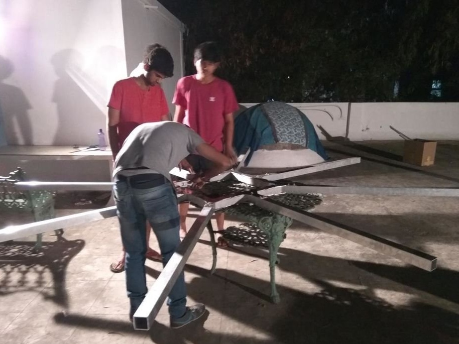
To fix the profiles to the brackets, the master drills holes for the bolts.
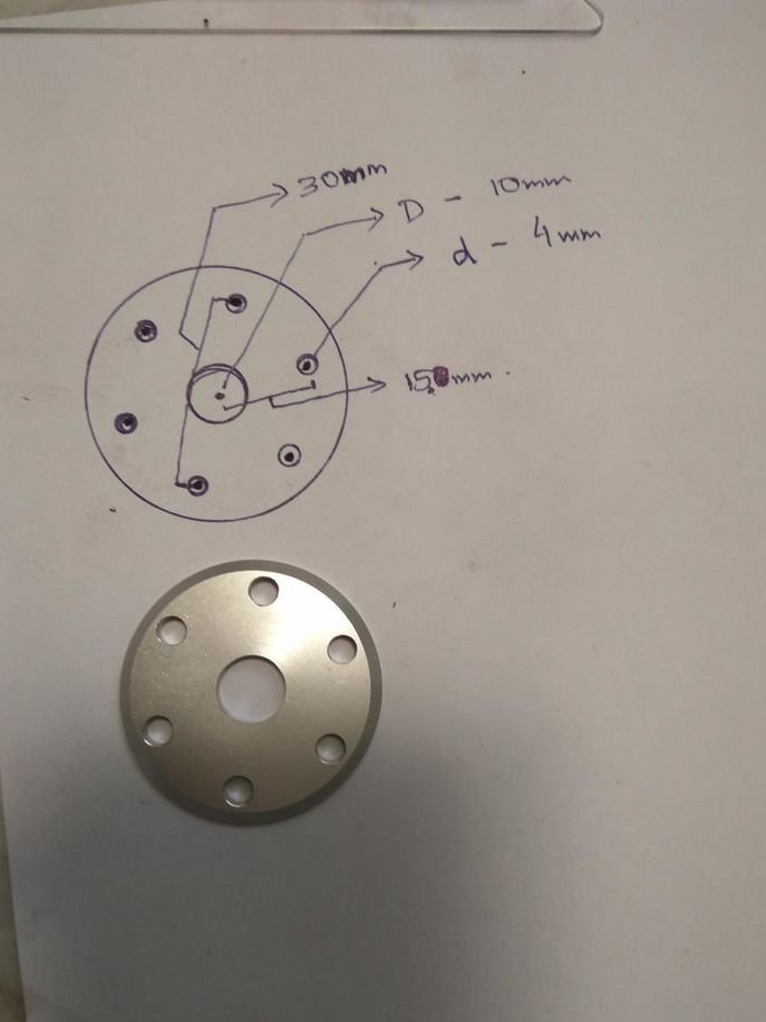
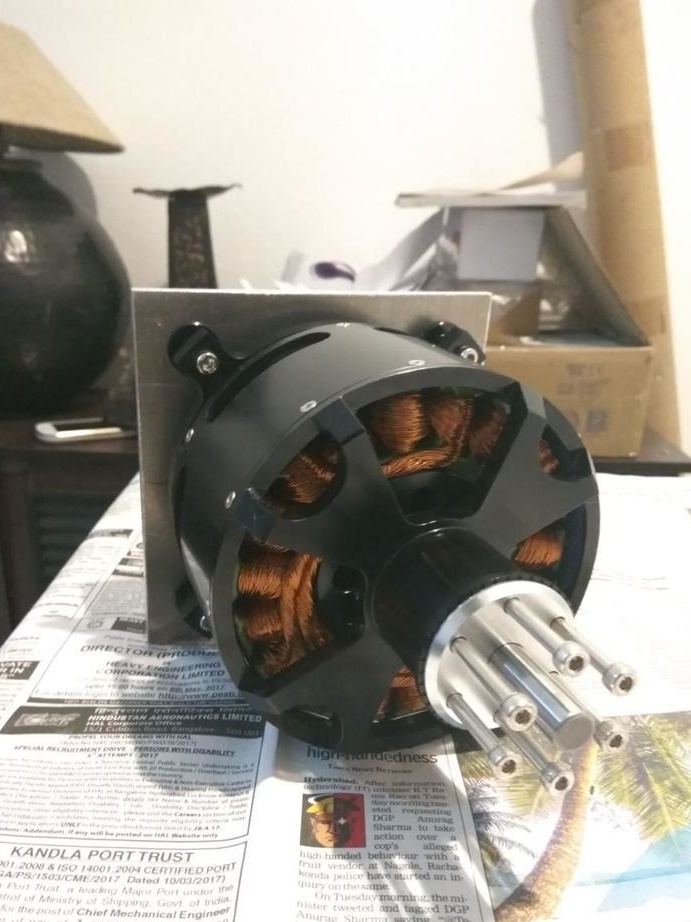
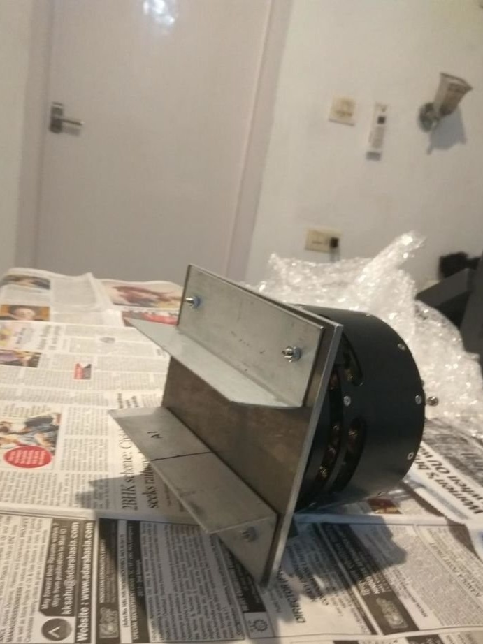
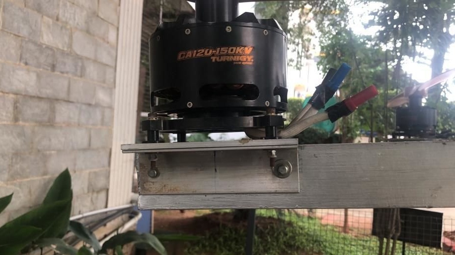
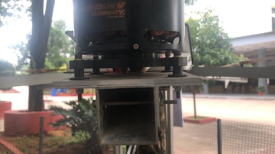
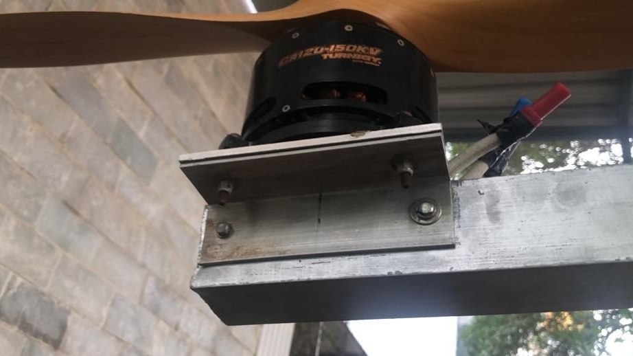
Step Five: Engine Mount
Engines are screwed onto an aluminum square plate. From the bottom of the plate, parallel to each other, two corners are screwed. The distance between them is equal to the width of the profile. Further, the plate with the engine is mounted on the profile, the mounting holes are drilled and everything is twisted with bolts.
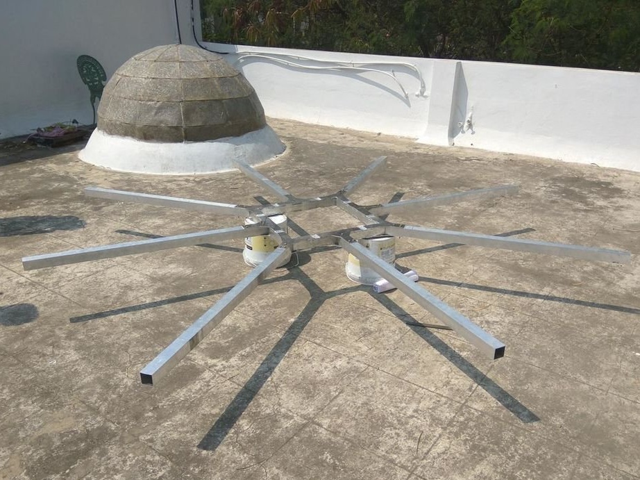
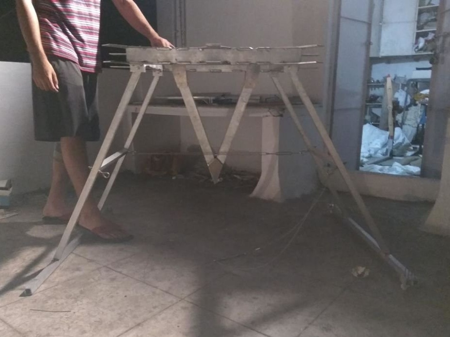
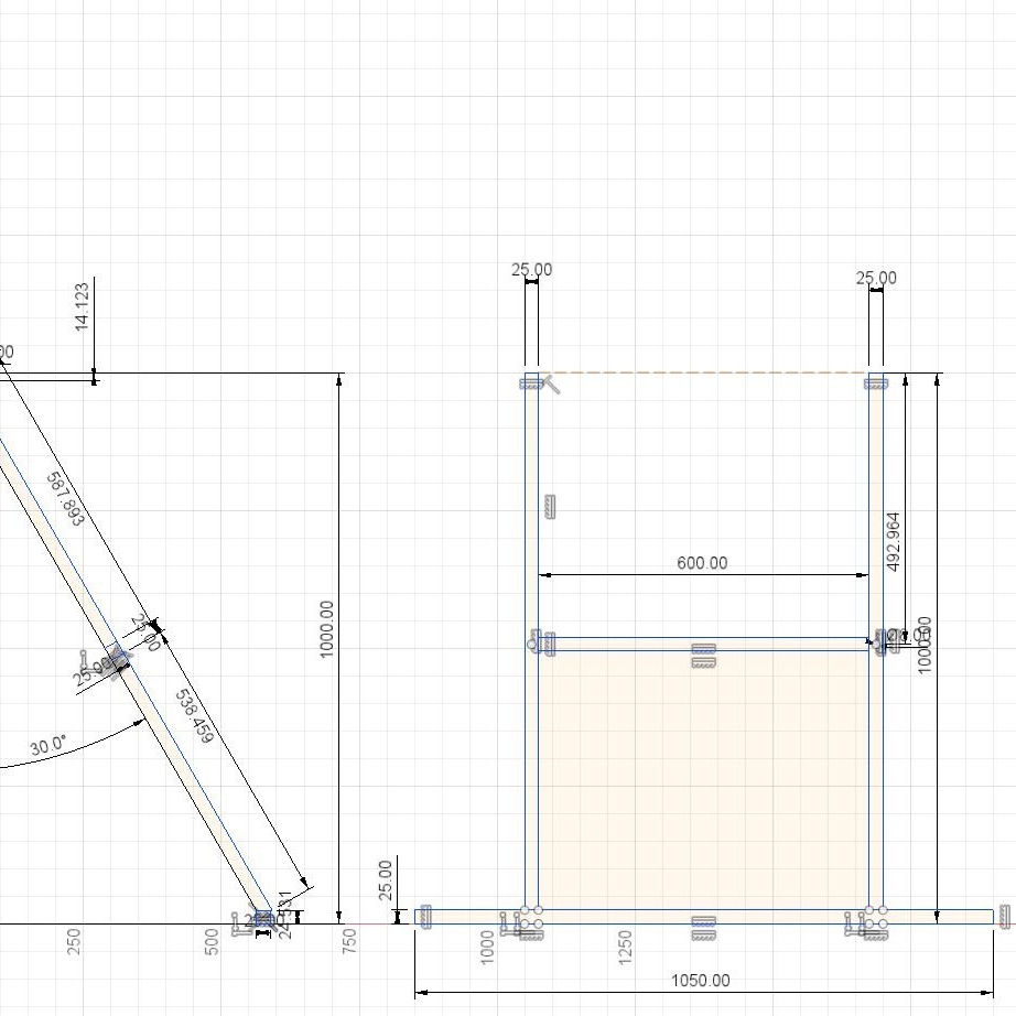
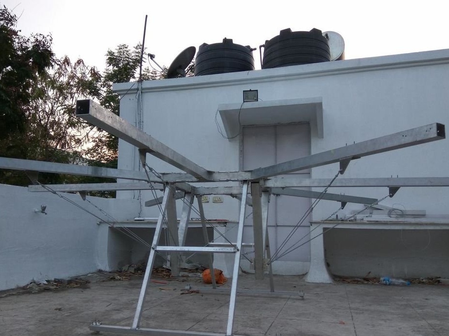
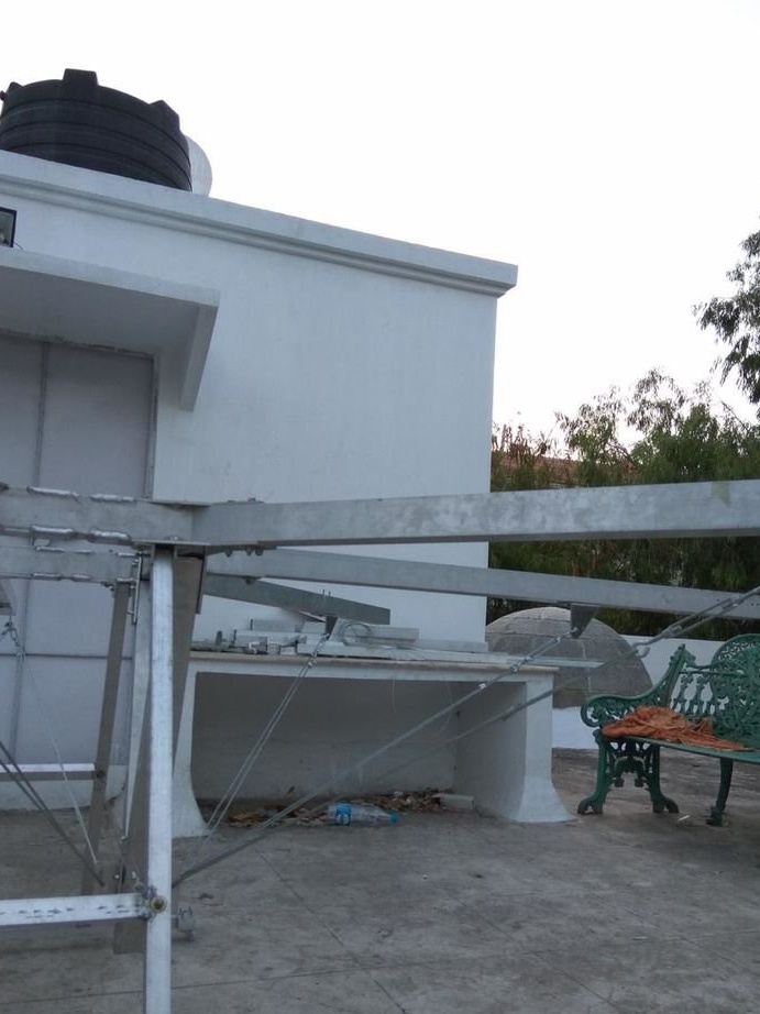
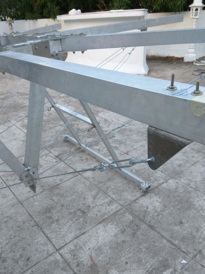
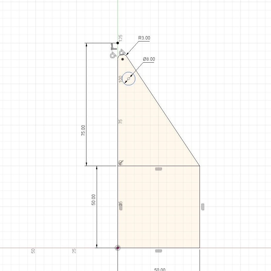
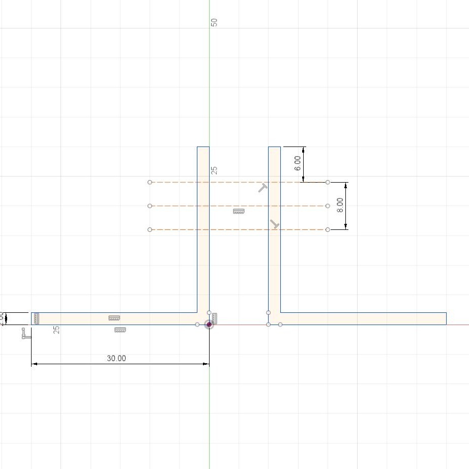
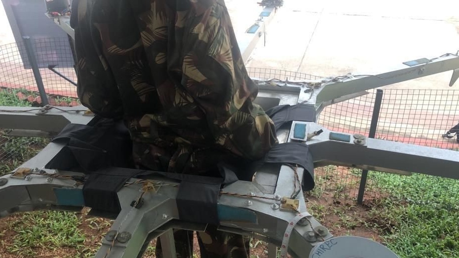
Step Six: Chassis
The chassis was made of aluminum profiles 25 x 25 mm and a thickness of 3 mm. All parts were welded, and their sizes can be seen in the photo. The idea was to mount the chassis out of the basket at an angle of 30 degrees. To prevent damage to the chassis, support cables are pulled between them.
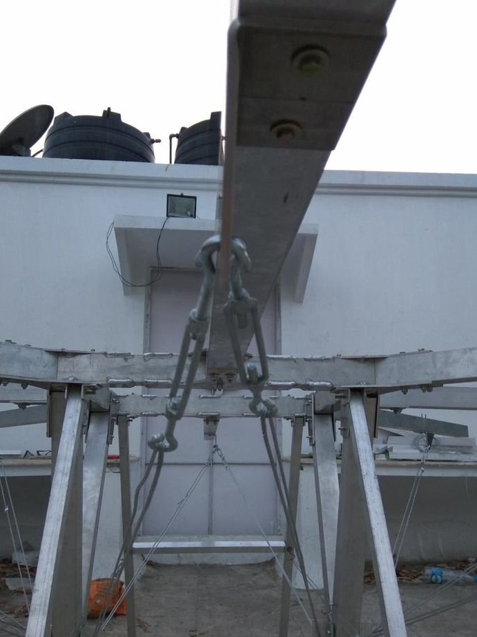
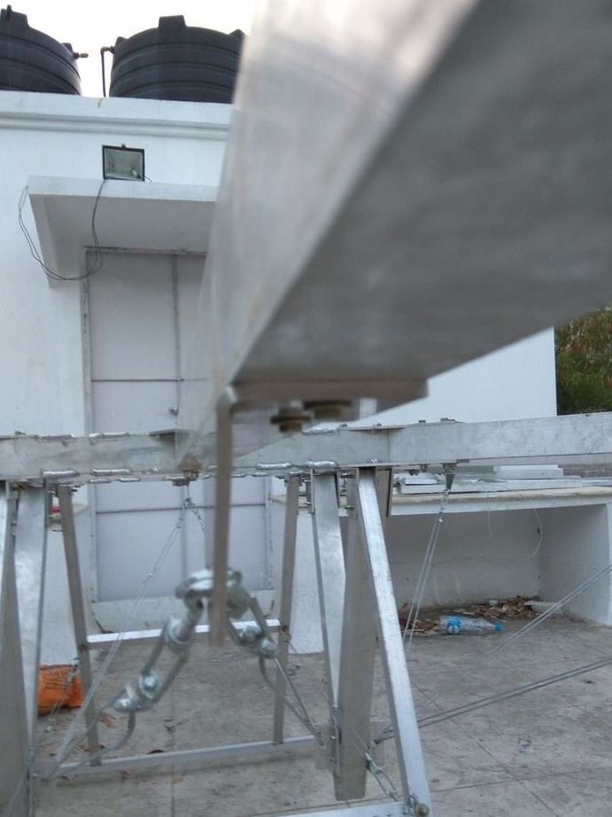
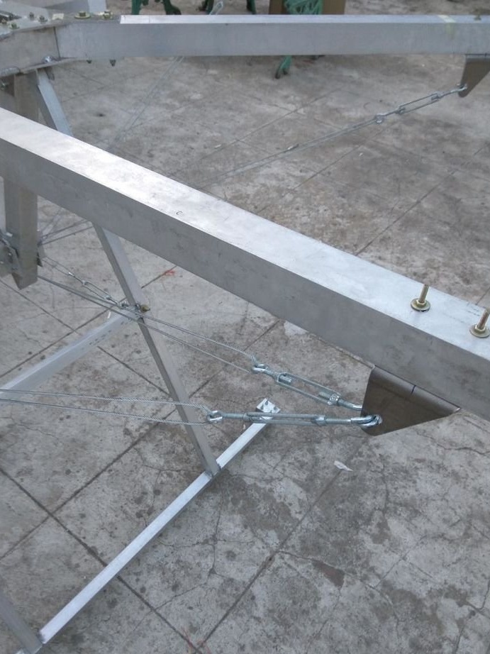
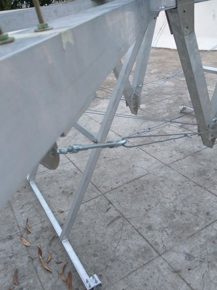
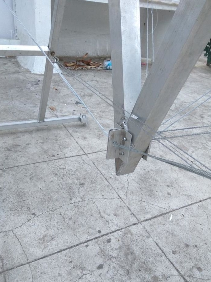
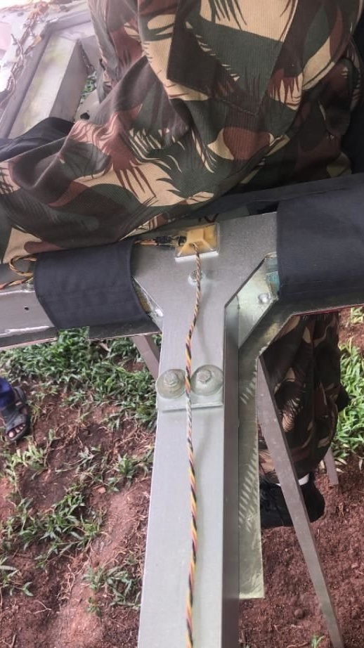
Step Seven: Supporting Support Profiles
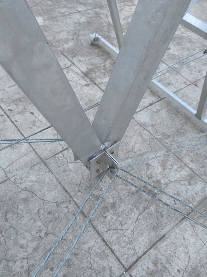
After installing the engines, the supporting profiles began to bend. Then the master tried to start the engine, and found out that the profiles "walk". It was necessary to strengthen the design.
Adding plates would add too much weight to the structure. Then the master decided to make a V-shaped design from the basket down. Ropes are attached to its lower part. The other ends of the cables are attached to the brackets in the middle of the supporting profiles. Cables are pulled with a hoist. Thus, the structure becomes stiff.

Step Eight: Connect
First, the master solders the connectors to the ends of the wires.
Then begins the installation. Each engine had to be checked for direction of rotation. If necessary, it is easy to change the direction of rotation of the engine, and, accordingly, the screw, swapping two of the three wires coming from the ESC to the engine. After all the motors were connected correctly, the wizard made the installation according to the connection diagram from the manufacturer.
Flight controllers IMU DJI A3 are very sensitive to interference from metals, and the master was unable to configure the system due to interference. As a result, the master replaced A3 with the Naza M V2, which had a similar connection scheme. Naza M V2 worked very reliably.
Then the wizard connects the batteries. On each carrier profile, two 22.2 V batteries are connected in series.
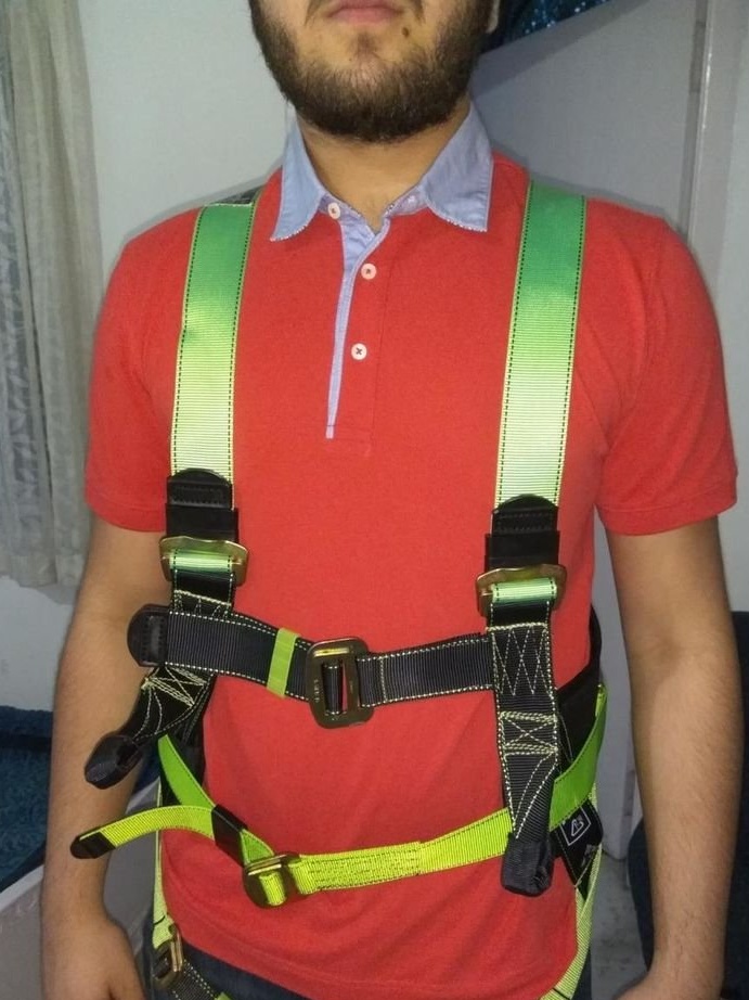
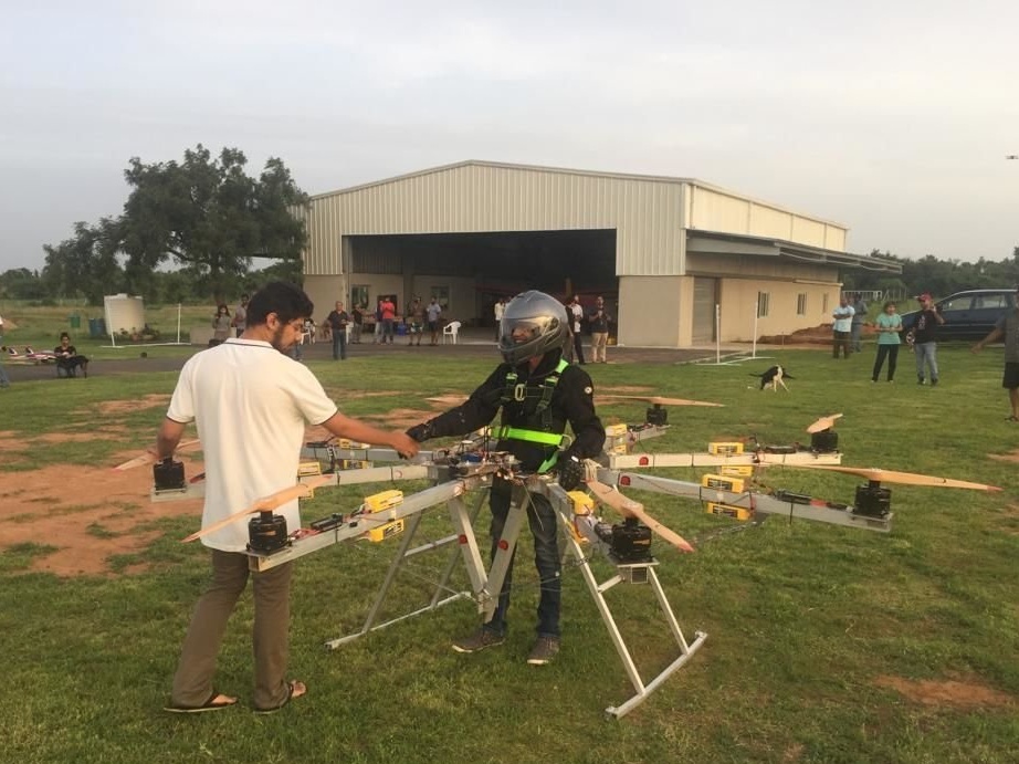
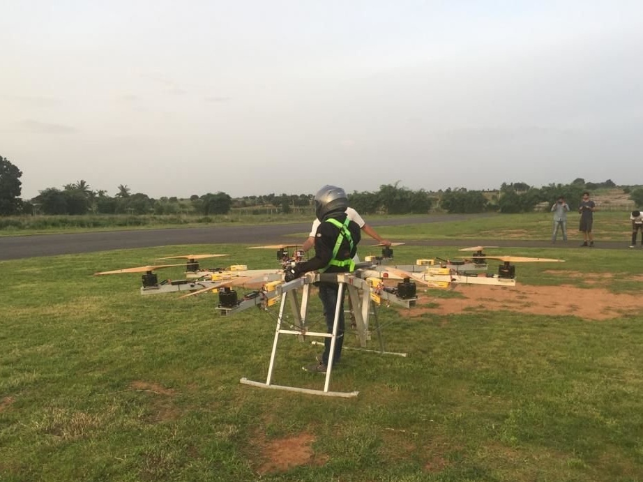
Step Nine: Pilot Seat
The seat was stitched from durable fabric. Also, a safety belt is attached to the pilot, which is attached to the frame, and a helmet.

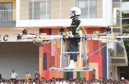
Step Ten: First Flight
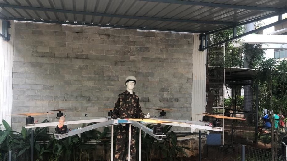
Before the pilot’s flight on the octocopter, several tests were carried out with a sandbag, and then with a model of a person. During the flight, various situations were simulated from loss of control to a gust of wind.
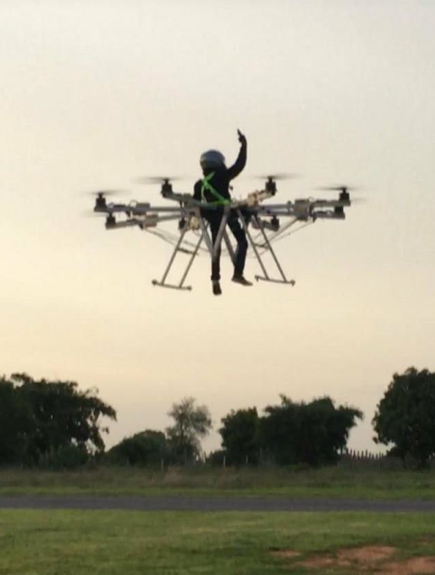
After all the tests, the pilot finally flew into the air.

Before flying, you must perform the following actions.
Check the tightness of bolts, cables, engine mounting.
Check the wiring.
Check that the screws rotate easily.
Make sure all ESCs are set to off.
Make sure all batteries are securely attached and charged.
Connect power to the flight controller for initialization and calibration.
After connecting to GPS, it will switch to fully automatic mode (Alt. + Att. Hold).
Sit in the pilot's seat and buckle up.
Connect all batteries to the ESC.
Connect the two batteries in series (ESC-RB-RB-ESC) using a resistor to eliminate the spark.
Turn on the motors by turning the switch to the on position.
Use the controller to control the octocopter.