The idea is borrowed from the project. ESP8266 Weather Display.
I decided to bring it to mind.
The following tasks were set:
- Update usage related code new version libraries ArduinoJson.h.
- Rewrite the code using the millis () function instead of the delay () function. It is clear that using delay to set a pause between changing information on the display, it is impossible to implement button controls;
- Make download sketches via Wifi;
- Get away from the bulky Wemos D1 R2 on the Wemos D1 mini;
- Whenever possible Russify display;
- Use a ready-made case with button holes for devices based on LCD1602;
- Use standard 6x6 buttons soldered to the breadboard. Add backlight control buttons, a carousel button for changing the displayed data and a button for forcing data updates from the server.
The following components were used:
- The case is made of ABS plastic with a set of covers for the buttons;
- Nylon struts 6 + 5 mm male M3 black, 4 pcs;
- M3 nylon nuts black, 4 pcs;
- Nylon posts 6 + 5 mm male M2 white, 3 pcs;
- Nylon stand 6 mm mother white, 1 pc;
- Nylon stand 8 mm mother white, 1 pc;
- Nylon racks 10mm mother white, 2 pcs;
- LCD 1602 (I2C), yellow;
- Wemos d1 mini;
- Wemos d1 DC-Power shield;
- Board breadboard 3x7;
- Buttons 6x6, height 7 mm, 3pcs;
- Dupont wires 10cm mother-mother, 4 pcs;
- 24 AWG wires black and red;
- Silicone wires 20 AWG blue and white;
- Resistors 5 kOhm - 2 pcs, 10 kOhm - 1 pc (which came to hand);
- Power adapter 9V 1A;
- Two-component epoxy adhesive.
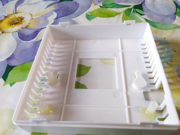
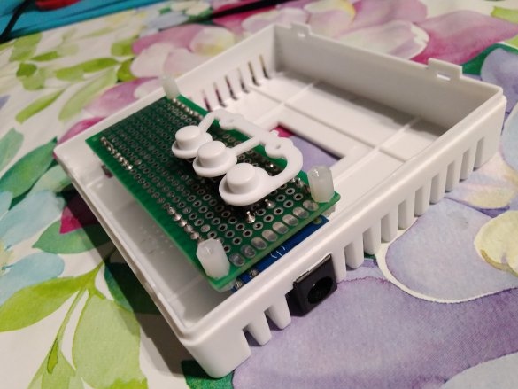
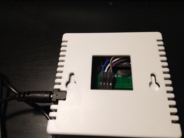
The used case has several advantages. Firstly, in addition to the display, the standard 3x7 standard decoupling board with its components installed on both sides is perfectly placed in height. Secondly, at two ends it has rectangular openings for cooling. It turned out that the jumpers between these holes are perfectly cut by mini-files 3 and 4 mm. If you cut a couple of jumpers and cut a small rectangular hole in the case, then the DC-005 power connector goes perfectly into the formed hole of complex geometry. Also, the back of this case has a large square hole, which, apparently, was supposed to install batteries.Through it, it is convenient to connect something inside without disassembling the case. Subsequently, it can simply be closed with glass or plastic.
Build progress:
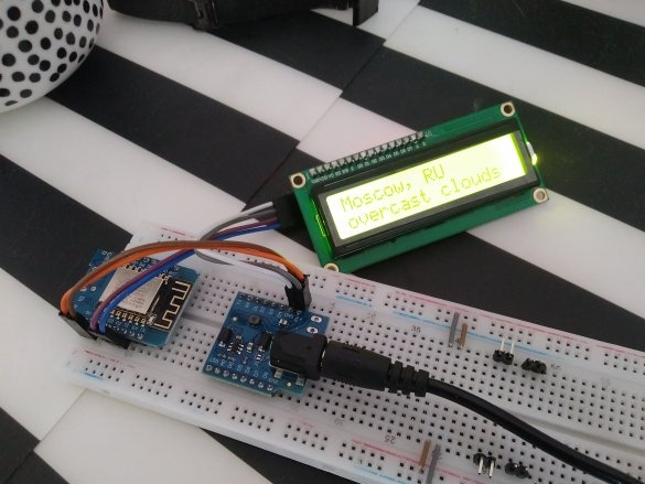
First, a prototype was made on a breadboard.
Then the case is finalized with a file.
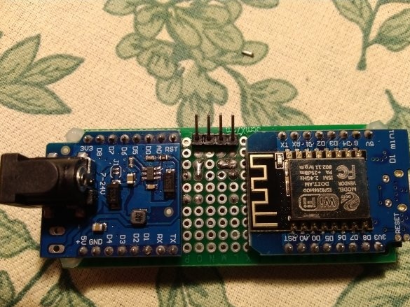
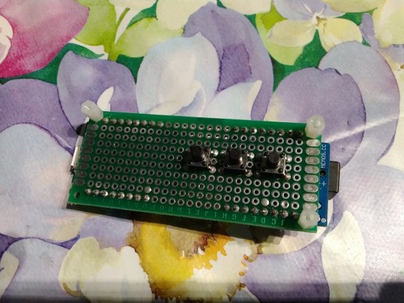
After that, the main components are soldered and the fitting is carried out. The legs were specially bent so that the detachable joints fit in height. A couple of nylon racks had to be filed so that all the buttons were at the same height.
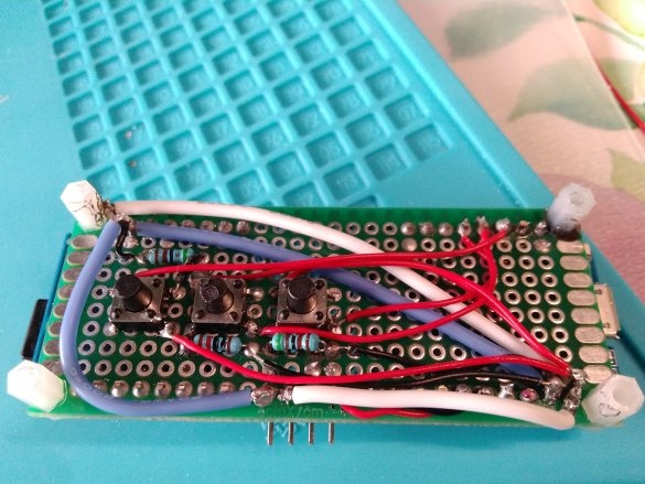
As a result, the front side of the board with buttons, resistors and wires is as follows:
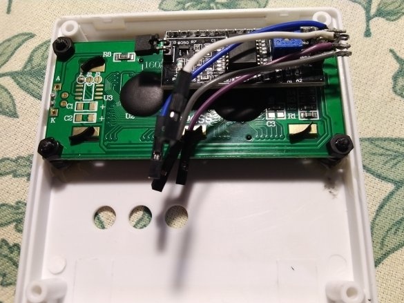
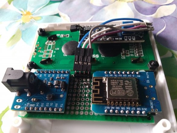
As a result, the insides of the device look like this:
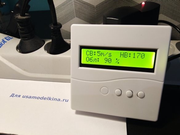
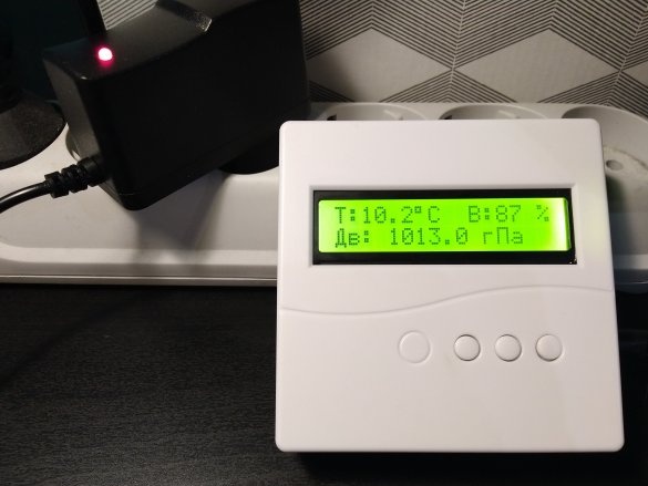
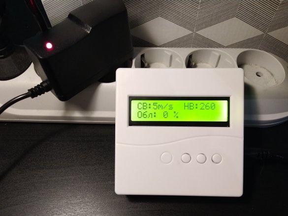
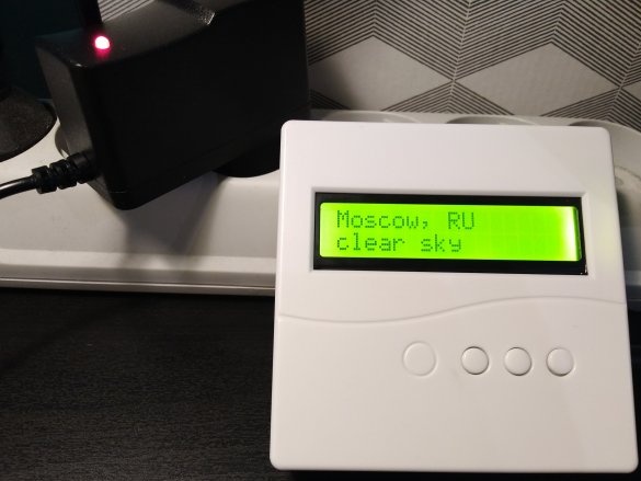
When assembled, the device looks like this:
Overcoming difficulties:
- For a long time I could not understand why the buttons did not work, although the multimeter clearly showed 0 when the buttons were pressed and 4.6 - 5.0 V when pressed (depending on the power supply). It turned out that in Wemos / Lolin devices it is necessary to indicate GPIO numbers as pin numbers in the sketch. For example, D5 is GPIO14. So this is the 14th pin.
const int buttonPin = 14; - To show the weather, the condition is necessary:
currentMillis - previousMillis == weatherTime
Strict correspondence, because it must be done once.
To make a request to the server, the condition is necessary:currentMillis - previousMillis> = getDataTime
Loose compliance, because it is executed until the “data received” flag is set.
In fact, this is not obvious, and to understand this, it took quite a long time. - I also had to torment myself with the server's response:
String weather = root ["weather"] [0] ["main"];
String description = root ["weather"] [0] ["description"];
Zero was completely unobvious. It turns out that there are two weather stations in Moscow, and the second of them does not always work (to receive data from it, you must specify [1] if it is active).
The repository with code and libraries is located here.


