
The author, under the nickname Electroniclovers123, tells how to make a simple built-in voltage meter on an ATmega8 microcontroller and a display on a chip compatible with HD44780 (KB1013VG6). The following is a diagram of the device:
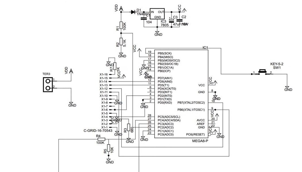
The ammeter shunt is two resistors of 0.33 Ohm and a power of 5 W connected in parallel. One of them is not visible in the diagram due to improper cropping of the image by the master himself. The left terminal of the shunt is connected to the common wire of the ampervoltmeter, and the right one is connected to terminal 26 of the microcontroller. Using the ADC, the microcontroller measures the voltage drop on this shunt. Thus, the common wire of the load PSU is connected to the common wire of the ampervoltmeter, but it cannot be connected to the common wire of the load itself, otherwise part of the current consumed by the load will bypass the shunt, and the ammeter readings will be distorted. The supply voltage of the load passes through the divider on the resistors to the terminal 27 of the microcontroller, and the supply voltage of the ampervoltmeter itself, not yet passed through the stabilizer, through another divider to the terminal 25 of the microcontroller. Thus, using the three ADCs built into the microcontroller homemade can measure three parameters: the current consumed by the load, its supply voltage and its own supply voltage. The program contains all the necessary coefficients, taking into account the parameters of the shunt and voltage dividers. If they are different, the code can be adjusted and recompiled. To switch the display modes of information in the device provides a single button. And so the master received printed circuit boards (one for himself, one for a friend who also decided to assemble the same ampervoltmeter?) And all the necessary components:
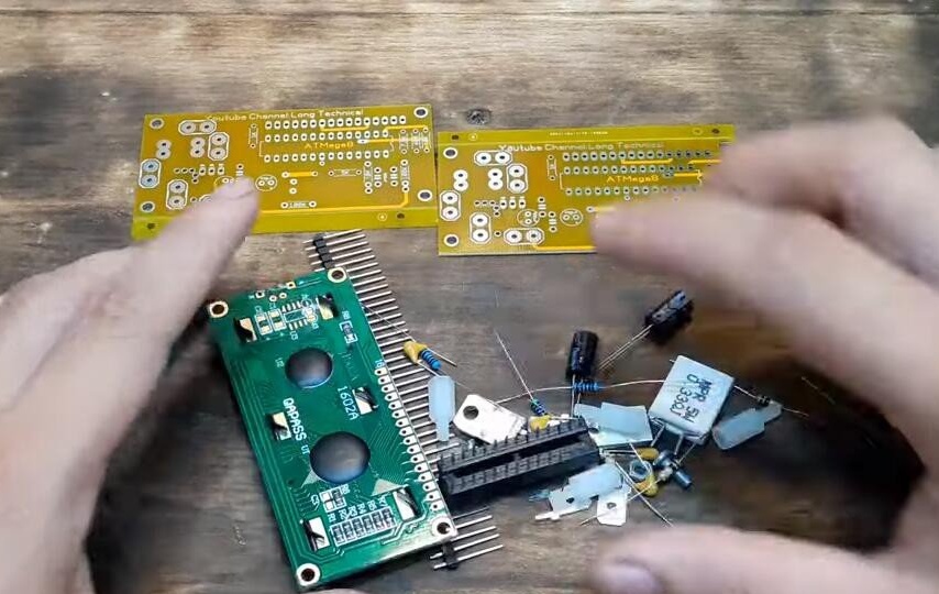
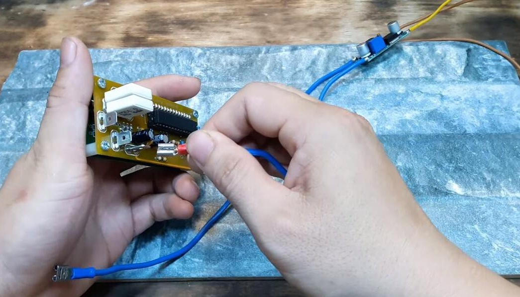
It solders all components into the board (by flashing the microcontroller in advance, this is not Arduino), not forgetting to install the stabilizer on the heat sink. This is especially important if the ammeter and load are powered by the same source, the voltage of which is noticeably greater than 5 V (but not more than 35). In some cases, you may need to increase the size of the heat sink.
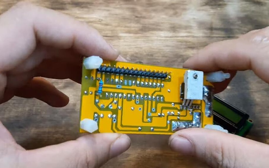
Provides flat contacts on the board for connectors similar to RPPI, and connects large conductors (for example, 2.5 mm) with these connectors2) for power supply and load. But to fully realize the capabilities of the conductors of this section (current up to 32 A) will prevent printed conductors that can not stand so much.
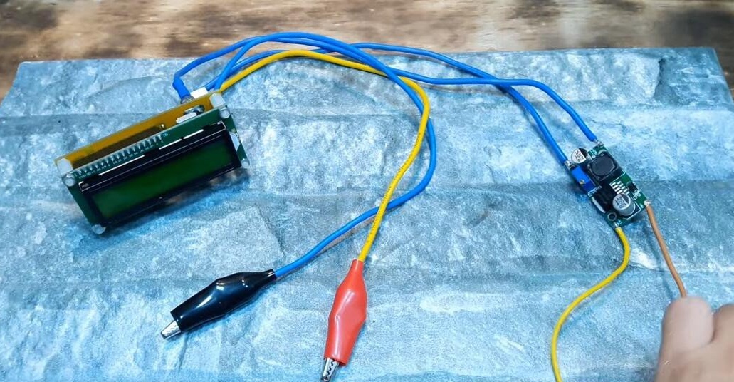
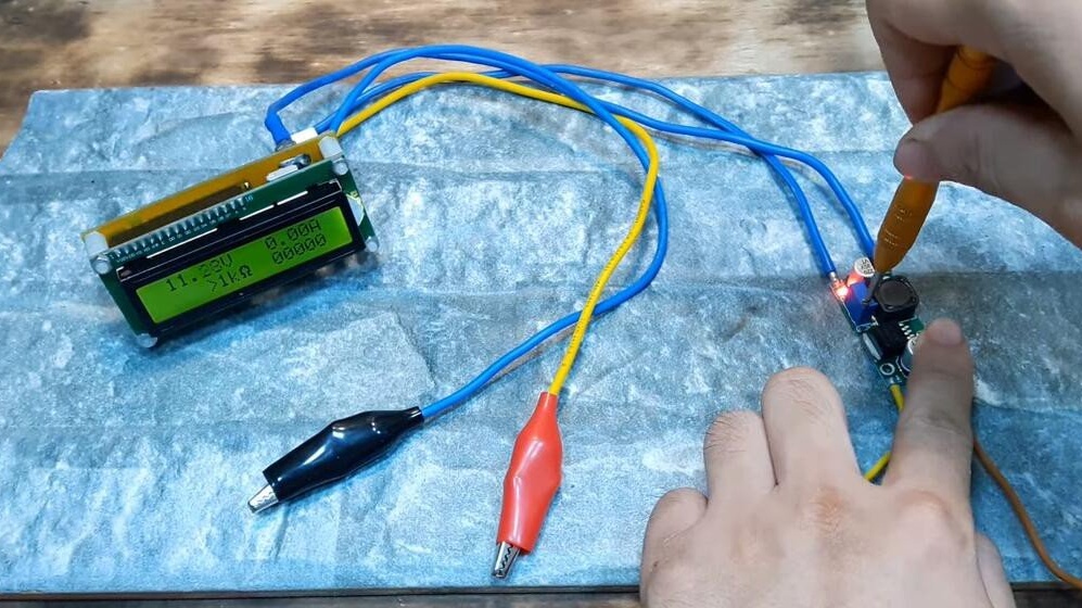
Then the master feeds the device from the pulse converter with 12 V output:

It turns on the power of the converter, the output voltage of which is regulated by a miniature screwdriver, slowly rotating the tuning resistor on its board. At the time of taking the screenshot from the video, this voltage is 11.28 V.
The following is the video itself with the assembly and setup process:
The archive with all the files necessary for repeating the ampervoltmeter, including firmware, lies here.