

I find it difficult to attribute this project to any one category. This is a combination of my own ideas and similar projects that I found on the Internet.
Step 1: Tools.
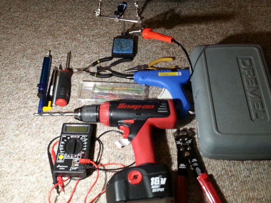
A milling cutter with a bunch of lotions is a great waste of money. Of course, she will not do all the work for you, but she will be a very convenient assistant. An electric drill will also cope with most of the tasks in this project.
The third hand also does not hurt, especially when soldering small parts.
Buy a good soldering iron that will not spoil your enjoyment of the process, but will clearly fulfill your soldering requirements.
You will need good pliers to strip the wires.
Also need a pair of pliers, a pair of wire cutters, a set of screwdrivers.
Prepare a solder suction
Hot glue gun
Multimeter
A pair of retractable blade knives and a set of mounting knives.
Step 2: Basic Materials

1) board for experiments.
2) soft solder
3) enameled wire. (I took my wires from the old TV)
4) cross wire. (I bought a set of wires for modeling, you can take any piece of solid wire).
5) the case, it should be large enough to accommodate a 9-volt battery with a clamp and 2-3 switches.
6) stranded wire.
Step 3: Material Specification
Parts and components.
1) 9v battery output
2) 2 single pole mini-circuit breakers
3) 40 Watt incandescent lamp with a large bulb
4) 1x 5 mm UV diode.
5) 10x ultra-bright SMD diodes
6) 1x 555 timer
7) 1 4017 decimal counter
8) 3x 1K resistor per ¼ Watt
9) 2x 10⁴ ceramic disk capacitors
10) 1x 10 electrolytic capacitor at 10 uF
11) 1x 100k linear potentiometer
12) 1x 9-volt alkaline battery
13) 1x 4.7K resistor per ¼ Watt
14) Tons of patience and understanding of electrical circuits.
Step 4: Cut the bottom of the lamp
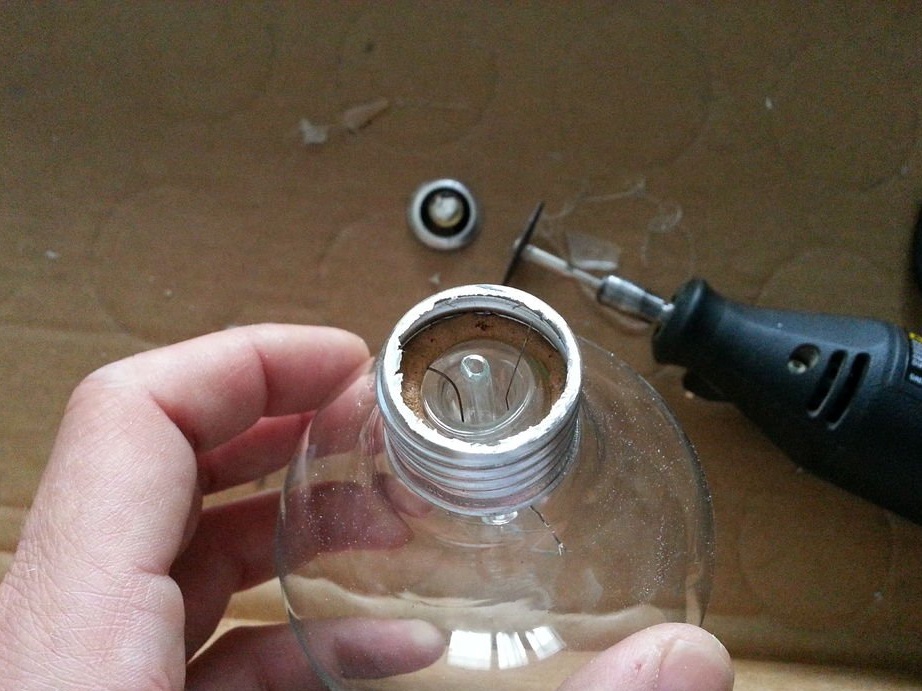
Use an abrasive cutting wheel to cut off the metal bottom of the incandescent lamp.
Then carefully cut the ledge of the lamp in the same circle.
Step 5: Gutting the Lamp

As soon as you get to the insides of the lamp, cutting off the bottom and the protrusion, very carefully crush the remaining glass inside with a screwdriver and pliers. As soon as all the unsoldered pieces of glass are removed, you need to remove the rest of the insides with a filament. I used a small diamond wheel, very carefully cutting out the glass core from the lamp. Be careful not to damage the outer bulb. Remove all entrails from the lamp.
I turned a hole inside the lamp with a round diamond rotary file.
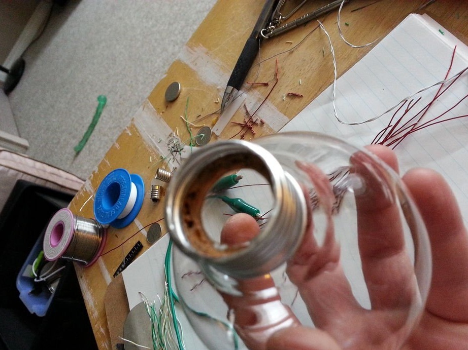
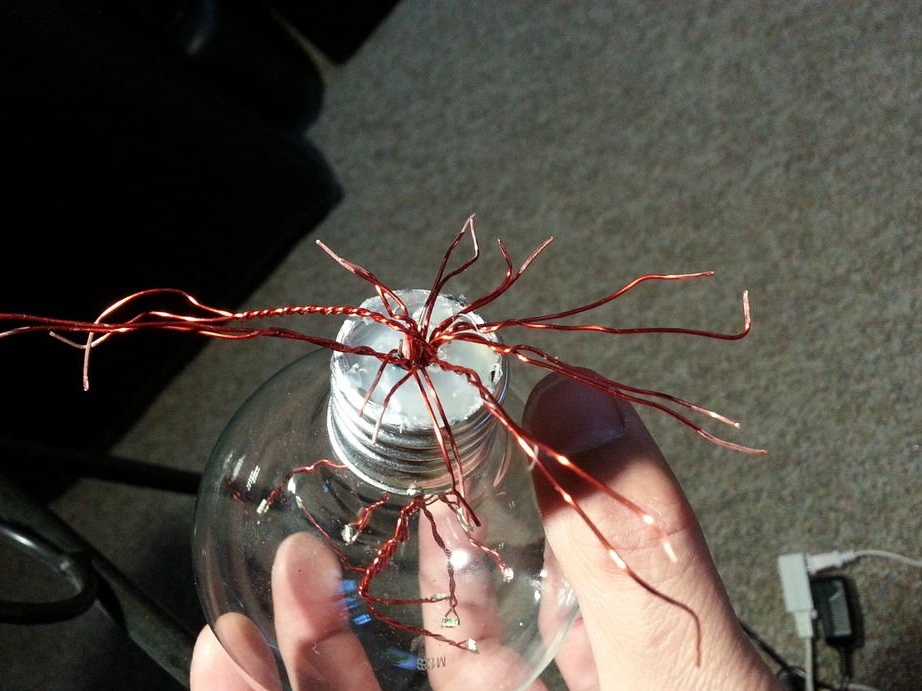
Step 6: Cooking the Wires
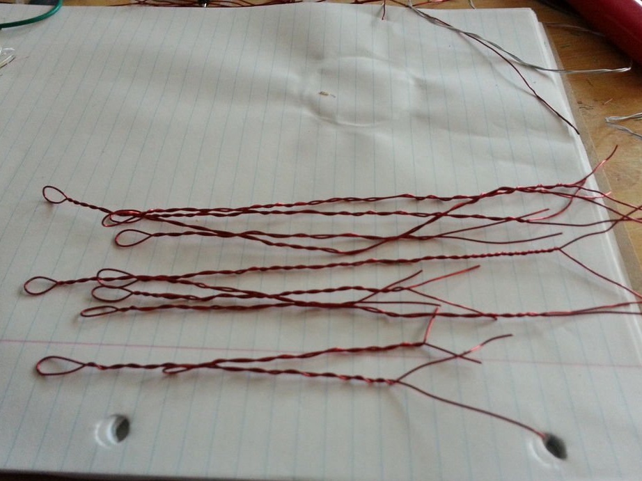
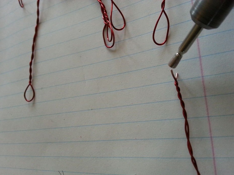
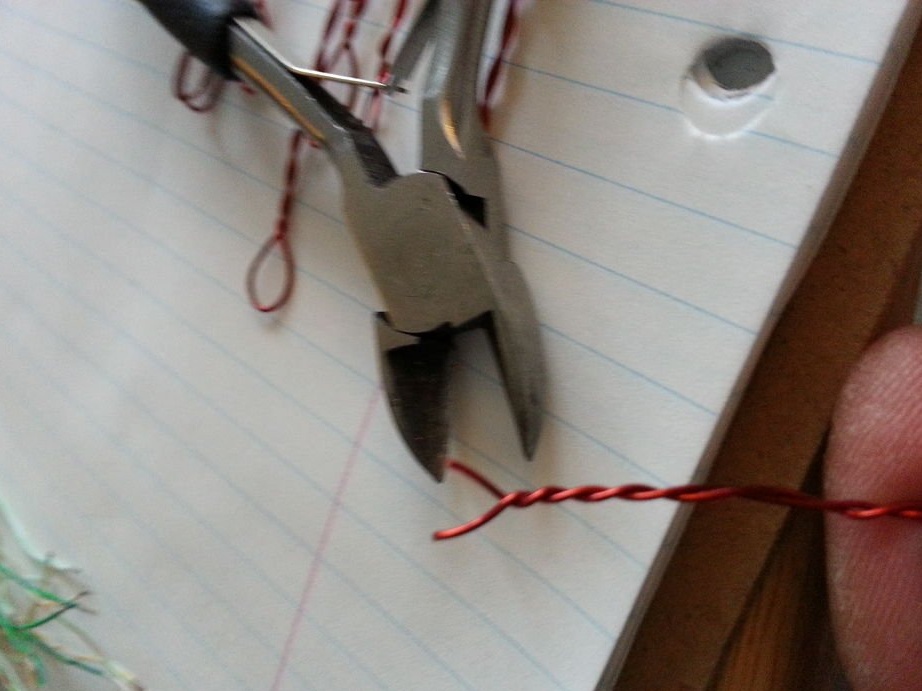
Fold the enameled wire in half and twist both halves together. Cut the edges and remove part of the winding. Again, I used a diamond rotary file. The loop on the edge will serve as a nest for tiny diodes, where we solder them. You can use any diodes to your taste.
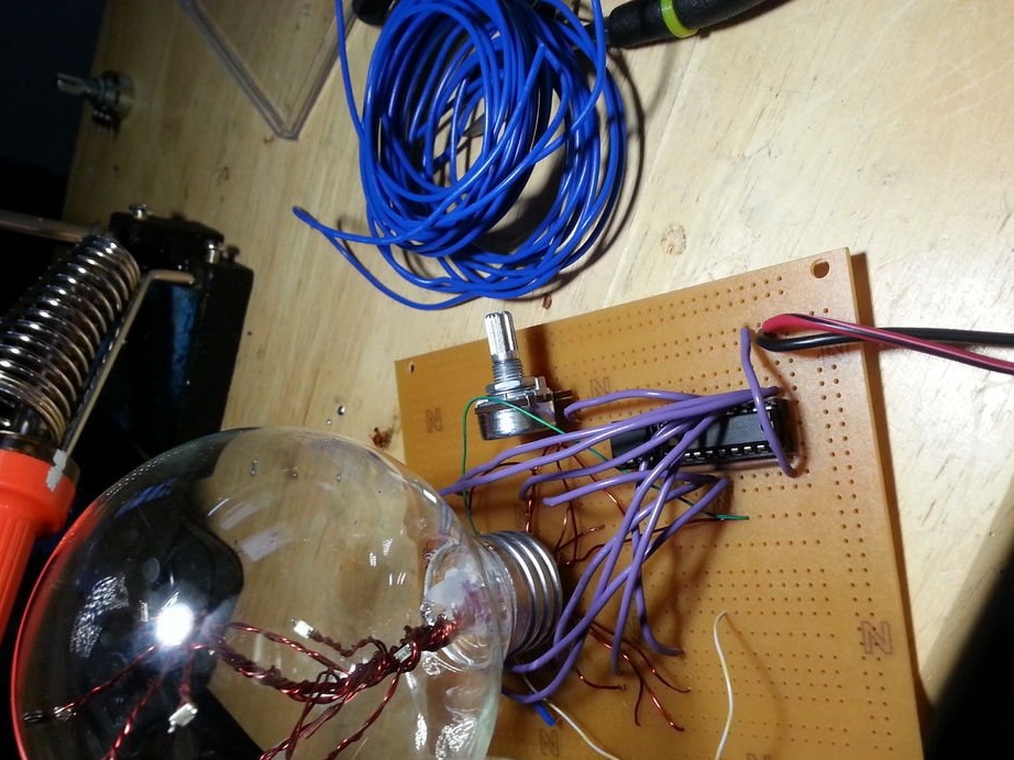
Step 7: make a tree
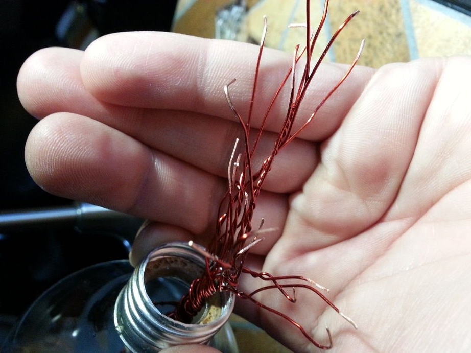
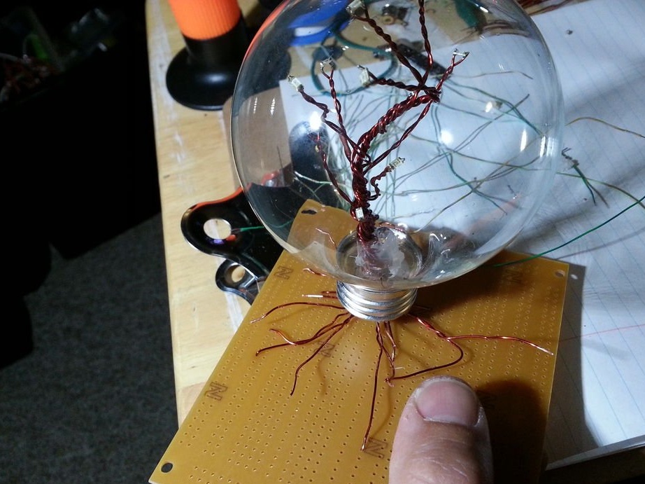
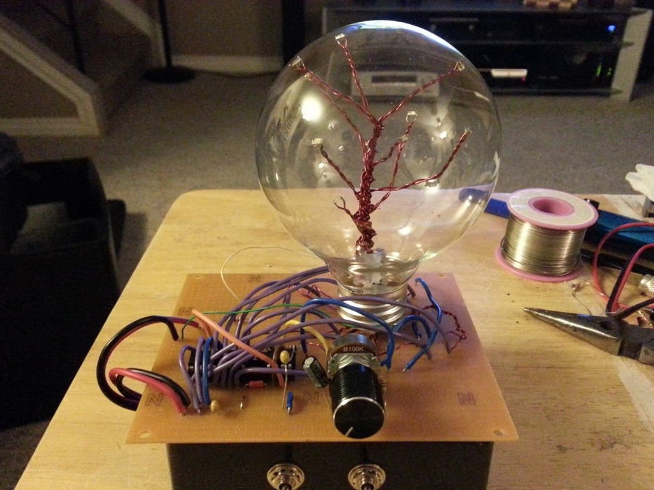
Twist the enameled wires with soldered diodes into a bundle and give it the shape of a tree. Insert this tree into the lamp bulb and use tweezers to bend the “branches” inside the bulb in the desired direction. Looks like dressing up a Christmas tree, right? Use a hot glue gun to fix the tree at the bottom of the bulb. I also added one UV diode for beauty. I used a battery to determine which wire is positive and which is negative. If you use a 3-volt battery and apply the wires very quickly, the diodes will survive the reverse bias voltage without loss. Solder the wires into one board and mark their polarity.
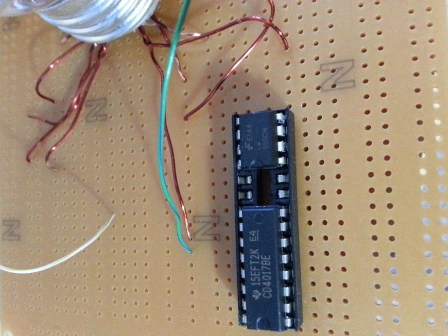
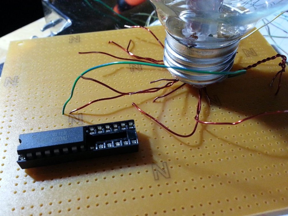
Step 8: Chain.
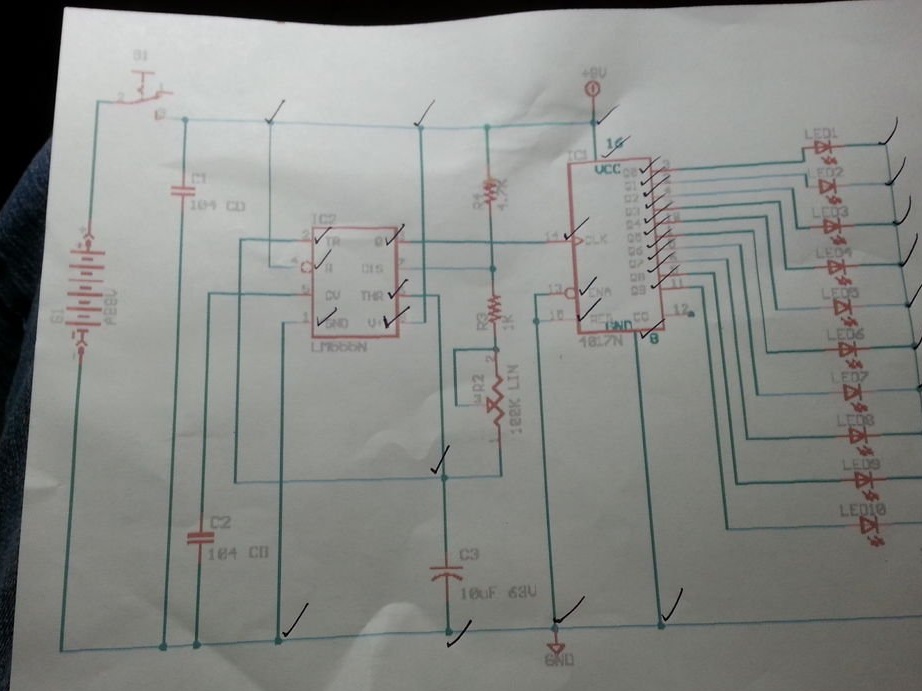
I googled the circuits of the flashing diode lamp, and chose this one. I apologize, I do not remember the source.
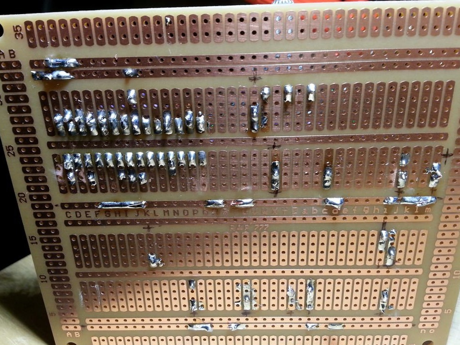
This circuit will randomly light 10 diodes. Synchronization and reset of contacts are controlled by the 555 chip. Unfortunately, I can’t show you the step-by-step assembly of the board, I just took it and mounted it without stopping in the photo. I wanted her to look natural, in a slight mess. So, in fact, it turned out :)
Step 9: Power Supply
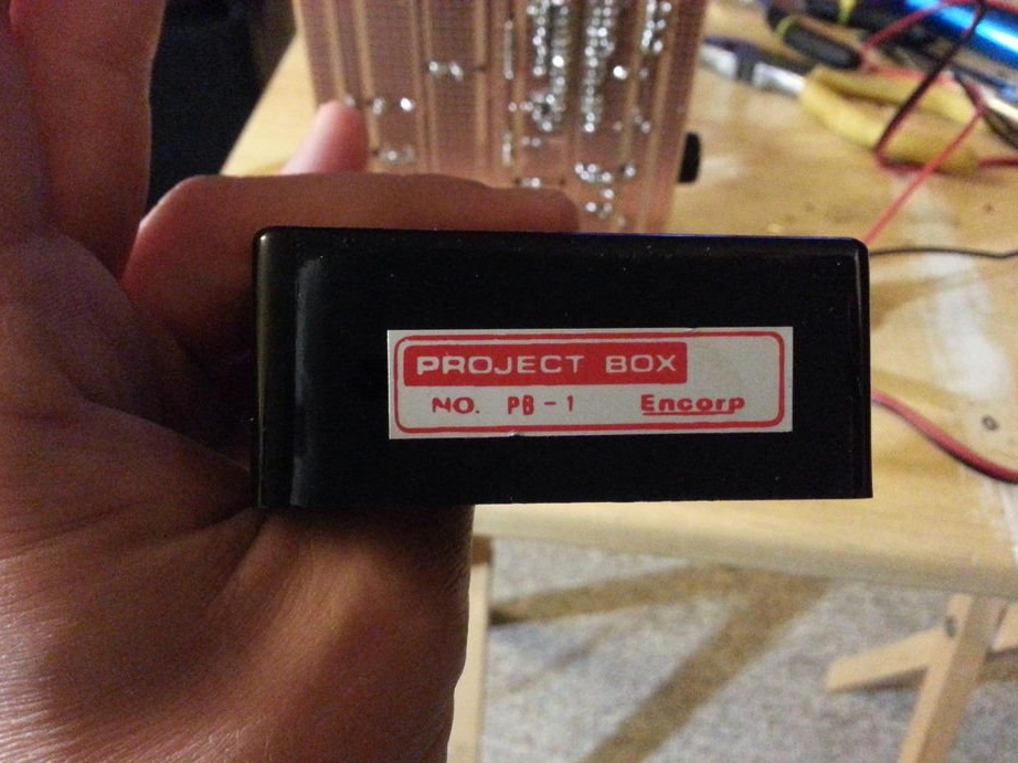
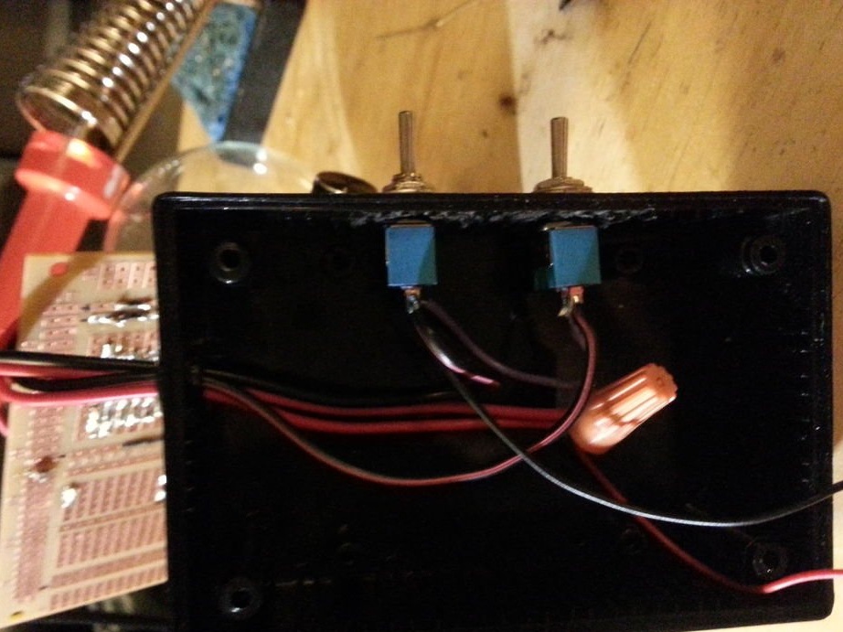
I used a small case and held two switches. One turns on the UV diode, and the second turns on the blinking circuit itself.
The circuit is powered by a 9-volt battery. The potentiometer controls the charge and discharge rate of the capacitors connected to the timer circuit 555. This allows you to adjust the blinking speed of the diodes. You will see in the dark how useful this is. At the beginning of the post there are two videos showing the work of this luminous tree. Happy viewing!